EP1224754B1 - Verfahren und einrichtung zur kontinuierlichen überwachung einer optischen übertragungsstrecke - Google Patents
Verfahren und einrichtung zur kontinuierlichen überwachung einer optischen übertragungsstrecke Download PDFInfo
- Publication number
- EP1224754B1 EP1224754B1 EP00983003A EP00983003A EP1224754B1 EP 1224754 B1 EP1224754 B1 EP 1224754B1 EP 00983003 A EP00983003 A EP 00983003A EP 00983003 A EP00983003 A EP 00983003A EP 1224754 B1 EP1224754 B1 EP 1224754B1
- Authority
- EP
- European Patent Office
- Prior art keywords
- signal
- transmission path
- transmission
- path
- monitoring
- Prior art date
- Legal status (The legal status is an assumption and is not a legal conclusion. Google has not performed a legal analysis and makes no representation as to the accuracy of the status listed.)
- Expired - Lifetime
Links
- 230000005540 biological transmission Effects 0.000 title claims abstract description 89
- 238000000034 method Methods 0.000 title claims abstract description 20
- 238000012544 monitoring process Methods 0.000 title claims description 44
- 230000003287 optical effect Effects 0.000 title claims description 36
- 230000008878 coupling Effects 0.000 claims abstract description 14
- 238000010168 coupling process Methods 0.000 claims abstract description 14
- 238000005859 coupling reaction Methods 0.000 claims abstract description 14
- 230000007547 defect Effects 0.000 claims abstract 4
- 238000005259 measurement Methods 0.000 claims description 13
- 238000012360 testing method Methods 0.000 claims description 11
- 238000000253 optical time-domain reflectometry Methods 0.000 claims 1
- 230000001960 triggered effect Effects 0.000 claims 1
- 230000008054 signal transmission Effects 0.000 abstract description 2
- 239000000835 fiber Substances 0.000 description 6
- 230000006378 damage Effects 0.000 description 5
- 239000013307 optical fiber Substances 0.000 description 5
- 230000008901 benefit Effects 0.000 description 2
- 238000004891 communication Methods 0.000 description 2
- 238000005516 engineering process Methods 0.000 description 2
- 238000011156 evaluation Methods 0.000 description 2
- 238000001914 filtration Methods 0.000 description 2
- 230000003993 interaction Effects 0.000 description 2
- 230000004807 localization Effects 0.000 description 2
- 229910004298 SiO 2 Inorganic materials 0.000 description 1
- 230000001419 dependent effect Effects 0.000 description 1
- 238000011161 development Methods 0.000 description 1
- 230000018109 developmental process Effects 0.000 description 1
- 238000000605 extraction Methods 0.000 description 1
- 230000008569 process Effects 0.000 description 1
- 238000012545 processing Methods 0.000 description 1
Images

Classifications
-
- H—ELECTRICITY
- H04—ELECTRIC COMMUNICATION TECHNIQUE
- H04B—TRANSMISSION
- H04B10/00—Transmission systems employing electromagnetic waves other than radio-waves, e.g. infrared, visible or ultraviolet light, or employing corpuscular radiation, e.g. quantum communication
- H04B10/07—Arrangements for monitoring or testing transmission systems; Arrangements for fault measurement of transmission systems
- H04B10/071—Arrangements for monitoring or testing transmission systems; Arrangements for fault measurement of transmission systems using a reflected signal, e.g. using optical time domain reflectometers [OTDR]
Definitions
- the invention relates to a method and device for continuous Monitoring an optical transmission line.
- the transmission links nowadays mostly briefly interrupted to find the right one To be able to couple measuring devices with which a transmission signal is coupled into the transmission path to test the transmission link. It can also a signal portion of the transmitted signal is coupled out, to test the transmission link.
- WaveWatcher® is a continuous Monitoring of an optical network enables. It deals is a relatively complex system with one Network element manager, an optical service channel and an element management system that is part of an optical network is embedded. The system monitors, measures and stores the status and operation of each module in the system. It a standard data communication network is used, which supported by the optical service channel for management information to process through the system. The data communication network allows remote access and remote control of the elements of network management. The Disadvantage of this system is that it is proportionate is complex.
- a system for monitoring optical networks from known from Lucent Technologies, which serves the Configuration, performance, security and other parameters an optical network on the level of network management to monitor.
- this system in particular, if an error occurs in the network, found out which components are affected. The operator can then decide what to do with these components, and he can inform the users of these circuits. Also this system is relatively complex.
- an optical fiber monitoring system for the continuous monitoring of the condition of optical fibers known, with a plurality of individual means for extraction optical energy from a plurality of optical fibers, each of the means being provided for optical energy extract from a fiber of the majority of the fibers, means for supplying the extracted energy to a monitoring means, which has a surveillance fiber that is extends from each of the individual means and the one fiber end in the monitoring means, the monitoring means Means to respond to the presence of the optical energy to generate one for the level of optical Indicative energy signal, measuring equipment for Receiving the signal so generated to determine if that optical signal indicating an optical fiber fault, localization means under the control of the measuring means for generating a fault location signal, and means for applying the error location signal on the optical fiber.
- the invention has for its object a continuous Monitoring an optical transmission link or one provide optical network with the simplest possible means.
- OTDR optical time domain reflectrometer in the time domain
- the reflected signals can be used achieve a spatial resolution, that is, over the term of the sample signal from the coupling to the reflection point and back to the decoupling as well as the intensity of the reflected Signals can be statements about the location and the Make kind of mistake.
- According to the invention is a continuous and uninterrupted Monitoring of the optical transmission path achieved, in particular the transmitted signal itself that means a fraction of the same, directly for measuring the quality the transmission link is used.
- the invention is advantageous because of the two measured variables, namely the reflected signal of the sample signal and the decoupled fraction of the transmitted signal, statements about the quality of the transmission path or errors in the transmission link, an increasing drop in the Transmission performance or an impending failure of the transmission link can be made.
- the measurement on the transmitted Signal gives a direct statement of the interaction between the transmission link and the transmitted one Signal while evaluating the sample signal in the event of an error a spatial resolution, that is, a localization of the Error.
- An advantageous embodiment of the method according to the invention is characterized in that the monitoring signal (S SUP ), that is to say the decoupled fraction of the transmitted signal (S IN ), is filtered before the measurement in such a way that signals lying only in the transmission band of the transmitted signal (S IN ) be allowed through.
- S SUP monitoring signal
- S IN decoupled fraction of the transmitted signal
- the saturation or destruction / damage of the receiver is avoided by the OTDR signal, which is known to have a high output power.
- the method is characterized in that the measurement result is processed according to a logic and that an alarm is given if an error is found. This is done a valuable processing of the measurement result for the user, so that the user can react accordingly.
- Another advantageous embodiment of the invention Procedure is characterized in that the intensity of the decoupled signal at 1-10% of the intensity of the transmitted Signal. So that is in an advantageous manner Total power of the signal transmitted when performing of the method according to the invention is only transmitted insignificantly reduced.
- the method is only a multiplexer and a Coupler required, and the link can be continuous and be monitored without interruption.
- An advantageous embodiment of the device according to the invention is characterized in that the coupler OTD reflectometer is connected downstream. With such a Device can advantageously be reflected from the Sample signal for the location of a fault in the transmission link getting closed.
- a great advantage of the device according to the invention lies in the optimal combination of the components WIC (Wavelength Independent Coupler) and WDM (Wavelength Division Multiplexer) in a module that provides the required function provides.
- the module only needs to be in an existing transmission system be used.
- An advantageous embodiment of the device according to the invention is characterized in that the multiplexer is a WDM is.
- the multiplexer is a WDM is.
- An advantageous embodiment of the device according to the invention is characterized in that the measuring device is a photodetector that detects the power of the output transmitted signal measures.
- An advantageous embodiment of the device according to the invention is characterized in that the facility for Evaluation of the measured, decoupled transmitted signal is a logic circuit with an alarm function.
- Another advantageous embodiment of the invention Device is characterized in that the coupling device is a so-called WIC, so that the module on a wide frequency range of transmitted signals can be used.
- the facility is characterized in that between the Coupling device and the measuring device an optical Bandpass filter is provided to filter out signal components that should not be measured in the measuring device, in particular, if a sample signal is in addition to the transmitted Signal is used, the sample signal should be filtered out to get an accurate measurement of the transmitted signal enable.
- an optical Bandpass filter is provided to filter out signal components that should not be measured in the measuring device, in particular, if a sample signal is in addition to the transmitted Signal is used, the sample signal should be filtered out to get an accurate measurement of the transmitted signal enable.
- the saturation or destruction or Damage to the receiver caused by the OTDR signal avoided which is known to have a high output power.
- a further advantageous embodiment of the device according to the invention is characterized in that two wavelength multiplexers are provided, of which one wavelength multiplexer for coupling the sample signal for the incoming part of the transmission path and the other wavelength multiplexer for coupling the sample signal (S OTDR, ab ) for the outgoing part the transmission link is provided.
- both parts of the transmission link can advantageously be monitored by one module.
- Another advantageous embodiment of the invention Device is characterized in that the multiplexer is arranged in front of the coupler in the transmission direction, wherein the filtering of the OTDR signal can be saved.
- WIC Wavelength Independent Coupler
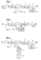
- the power component of the incoming signal S IN, which is coupled out at the gate T2 is in the range from 1 to 10% of the signal S IN coupled at the gate T1.
- an OTDR signal S OTDR is coupled into or out of the signal transmission path.
- the output signal S out is coupled out of the module at a gate T6 and output via a transmission link 10.
- the signal S OTDR is evaluated in an OTD refractometer 12.
- the wavelength of the signal S OTDR lies outside the transmission band of the transmitted signal. If the signal is transmitted in the third optical window (at approximately 1550 nm), the signal S OTDR can be at 1310 nm or above 1600 nm (typically at 1625 nm). If transmission takes place in the second optical window, the signal S OTDR is in the wavelength range from 1550 nm or also at 1625 nm.
- Fig. 2 shows the basic structure of a module for monitoring the outgoing branch of the transmission link.
- the same reference numerals are used for the same parts as in Fig. 1.
- a signal S OTDR coupled to the gate T5 has such a direction of movement that the outgoing branch of the transmission link or the transmission link 10 is monitored by the signal S OTDR .
- the behavior of the transmission link 10 in relation to the transmitted signal S out is then monitored in the next monitoring module in the transmission link, where a WIC is also provided, which then decouples part of the transmitted signal, which allows conclusions to be drawn about the transmission characteristics of the transmission link 10.
- FIG. 3 shows the module from FIG. 1, a photodetector and a logic circuit 16 being added, the photodetector 14 receives the decoupled fraction S SUP of the transmitted signal S IN and outputs a corresponding measured value to the logic circuit 16 which, for example, transfers a threshold value determination that determines the quality of the transmission link or an error in the transmission link and emits an electrical signal or an alarm signal.
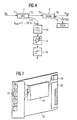
- Fig. 4 is a further advantageous embodiment of the module according to the invention, wherein a bandpass filter 18 is provided in front of the photodetector 14 so that the backscattered signal S OTDR does not fall on the photodetector 14 and falsifies the measurement or oversaturates or damages the detector.
- Fig. 5 shows in principle a structure of a module when the OTDR signal is coupled in the incoming and outgoing transmission link.
- a wavelength-independent coupler 30, a first wavelength multiplexer 32 and a second wavelength multiplexer 34 are provided in the transmission link 2.
- part of the signal S IN which arrives at the gate T1 of the coupler 30, is coupled out at the gate T2 of the coupler 30 as a monitoring signal S SUP .
- the transmission signal is sent from the gate T3 of the coupler 30 to the gate T4 of the first wavelength multiplexer 32.
- the sample or OTDR signal S OTDR, ank is coupled in, which is intended to monitor the incoming part of the monitoring path.
- the transmitted signal is output at the gate T6 of the wavelength multiplexer 32 and input into the second wavelength multiplexer 34 at the gate T7.
- the transmitted signal is output at the gate T8 of the wavelength multiplexer 34 as a signal S OUT .
- a sample signal S OTDR, ab is coupled in at the gate T9 and is intended to monitor the outgoing part of the transmission link.
- the coupler 30 and the wavelength division multiplexers 32, 34 can in turn be combined in one module.
- FIG. 6 shows the basic structure of a module for monitoring optical transmission links, the same components as in the exemplary embodiment from FIG. 1 being used. 1, however, the wave multiplexer 8 is arranged in front of the coupler 4 in the transmission direction, which is represented by the signals S IN and S OS .
- the sample signal S OTDR coupled in the wavelength multiplexer 8 is used to monitor the incoming part of the monitoring path.
- This embodiment of the invention has the further advantage that the filtering of the OTDR signal can be saved because this signal is decoupled in front of the coupler 4 and therefore cannot reach the detector.
- the overall module can be constructed from discrete individual components or can be an optically integrated component based on SiO 2 , Si or InP technology.
- the total attenuation of the signal between gate T1 and gate T6 is less than 3 dB.
- FIG. 7 shows an insert with a printed circuit board 20 the monitoring module 24, a panel with fiber optic couplings 22, in particular couplings for the channels Ch.1 to Ch.4, one Output 26 for an electrical alarm or a power supply and a network interface 28.
- monitoring module is described as being a wavelength independent Coupler 4 or 30 in combination with one or several wavelength multiplexers 8 or 32, 34 note that monitoring functions of these two Components can be used separately.
Landscapes
- Physics & Mathematics (AREA)
- Electromagnetism (AREA)
- Engineering & Computer Science (AREA)
- Computer Networks & Wireless Communication (AREA)
- Signal Processing (AREA)
- Optical Communication System (AREA)
- Monitoring And Testing Of Transmission In General (AREA)
Abstract
Description
- Fig. 1
- den prinzipiellen Aufbau eines Moduls zur Überwachung von optischen Übertragungsstrecken, wenn der ankommende Zweig einer Übertragungsstrecke überwacht werden soll;
- Fig. 2
- den prinzipiellen Aufbau eines Moduls zur Überwachung von optischen Übertragungsstrecken, wenn der abgehende Zweig einer Übertragungsstrecke überwacht werden soll;
- Fig. 3
- den prinzipiellen Aufbau eines Moduls wie in Fig. 1 mit der Ergänzung eines Photodetektors und einer Logikschaltung zur Erzeugung eines Alarmsignals;
- Fig. 4
- den prinzipiellen Aufbau eines Moduls wie in Fig. 1 mit der Ergänzung eines Photodetektors und einer Logikschaltung zur Erzeugung eines Alarmsignals mit einem zusätzlichen optischen Filter;
- Fig. 5
- den prinzipiellen Aufbau eines Moduls, wenn das OTDR-Signal sowohl in die ankommende als auch in die abgehende Übertragungsstrecke eingekoppelt wird;
- Fig. 6
- den prinzipiellen Aufbau eines Moduls zur Überwachung von optischen Übertragungsstrecken als Alternative zu Fig. 1; und
- Fig. 7
- einen Einschub mit einem Modul gemäß der Erfindung.
Claims (14)
- Verfahren zur kontinuierlichen Überwachung einer optischen Übertragungsstrecke, wobei wellenlängenunabhängig ein Bruchteil eines übertragenen oder ankommenden Signals (SIN) ohne Unterbrechung der Überwachungsstrecke ausgekoppelt wird; wobei ein Probensignal in die Überwachungsstrecke ohne Unterbrechung der Überwachungsstrecke eingekoppelt wird, wobei das von der Übertragungsstrecke reflektierte Probensignal ohne Unterbrechung der Überwachungsstrecke ausgekoppelt wird, wobei die Frequenz des Probensignals außerhalb des Übertragungsbandes des übertragenen Signals gewählt wird und wobei aufgrund einer Messung des ausgekoppelten Signal-Bruchteils (SSUP) sowie des reflektierten Probensignals eine Aussage über die Güte der Übertragungsstrecke beziehungsweise einen Fehler in der Übertragungsstrecke gemacht wird.
- Verfahren nach Anspruch 1, wobei das Probensignal. ein OTDR-Signal (SOTDR) ist.
- Verfahren nach Anspruch 1 oder 2, wobei das Überwachungssignal (SSUP), das heißt der ausgekoppelte Bruchteil des übertragenen Signals (SIN) vor der Messung gefiltert wird derart, dass nur im Übertragungsband des übertragenen Signals (SIN) liegenden Signale durchgelassen werden.
- Verfahren nach einem der Ansprüche 1 bis 3, wobei das Messergebnis nach einer Logik verarbeitet wird, und wobei ein Alarm gegeben wird, wenn ein Fehler festgestellt wird.
- Verfahren nach einem der Ansprüche 1 bis 4, wobei die Leistung des ausgekoppelten Überwachungssignals (SSUP) bei 1 bis 10% der Leistung des übertragenen Signals (SIN) liegt.
- Verfahren nach einem der vorhergehenden Ansprüche, wobei das Probensignal in die Übertragungsstrecke des ankommenden oder des abgehenden, übertragenen Signals eingekoppelt wird.
- Einrichtung zur kontinuierlichen Überwachung einer optischen Übertragungsstrecke, mit einem Wellenlängen-Multiplexer (8), über den ein Probensignal (SOTDR), dessen Frequenz außerhalb des Übertragungsbandes des übertragenen Signals liegt, in die Übertragungsstrecke ohne Unterbrechung derselben einzukoppeln beziehungsweise ein reflektiertes Signal aus der Übertragungsstrecke ohne Unterbrechung derselben auszukoppeln ist, einem Wellenlängen-Koppler (8), mit dem das reflektierte Signal aus der Übertragungsstrecke ohne Unterbrechung derselben ausgekoppelt wird, einer wellenlängenunabhängigen Kopplungseinrichtung (4), mit der ein Bruchteil eines übertragenen oder ankommenden Signals (SIN) als Überwachungssignal (SSUP) auszukoppeln ist, einer Messeinrichtung (14) zum Messen des ausgekoppelten Überwachungssignals (SSUP) und jeweils einer dem Wellenlängen-Koppler (8) bzw. der Kopplungseinrichtung (4) zugeordneten Einrichtung (12, 16) zum Auswerten des gemessenen Überwachungssignals (SSUP) und des reflektierten Signals unter Erstellen einer Aussage über die Güte der Übertragungsstrecke beziehungsweise über einen Fehler in der Übertragungsstrecke.
- Einrichtung nach Anspruch 7, wobei dem Koppler (8) ein OTD-Reflektometer (12) nachgeschaltet ist.
- Einrichtung nach Anspruch 7 oder 8, wobei die Messeinrichtung (14) ein Photodetektor ist.
- Einrichtung nach einem der Ansprüche 7 bis 9, wobei die Einrichtung zur Auswertung des gemessenen, ausgekoppelten, übertragenen Überwachungssignals (SSUP) eine Logikschaltung (16) mit Alarmfunktion ist.
- Einrichtung nach einem der Ansprüche 7 bis 10, wobei zwischen der Kopplungseinrichtung (4) und der Messeinrichtung (14) ein Bandpassfilter (18) angeordnet ist.
- Einrichtung nach einem der Ansprüche 7 bis 11, wobei zwei Wellenlängenmultiplexer (32), (34) vorgesehen sind, von denen der eine Wellenlängenmultiplexer (32) zum Einkoppeln des Probensignals (SOTDR,ank) für den ankommenden Teil der Übertragungsstrecke und der andere Wellenlängenmultiplexer (34) zum Einkoppeln des Probensignals (SOTDR,abg) für den abgehenden Teil der Übertragungsstrecke vorgesehen ist.
- Einrichtung nach einem der Ansprüche 7 bis 12, wobei der Multiplexer (8) in Übertragungsrichtung vor dem Koppler (4) angeordnet ist.
- Einrichtung nach einem der Ansprüche 7 bis 13, wobei die Einrichtung, die einen Modul zur Überwachung von optischen Übertragungsstrecken bildet, auf einer Leiterplatte beziehungsweise auf einem Einschub angeordnet ist.
Applications Claiming Priority (3)
| Application Number | Priority Date | Filing Date | Title |
|---|---|---|---|
| DE19949401 | 1999-10-13 | ||
| DE19949401A DE19949401A1 (de) | 1999-10-13 | 1999-10-13 | Verfahren und Einrichtung zur kontinuierlichen Überwachung einer optischen Übertragungsstrecke |
| PCT/DE2000/003618 WO2001028133A2 (de) | 1999-10-13 | 2000-10-13 | Verfahren und einrichtung zur kontinuierlichen überwachung einer optischen übertragungsstrecke |
Publications (2)
| Publication Number | Publication Date |
|---|---|
| EP1224754A2 EP1224754A2 (de) | 2002-07-24 |
| EP1224754B1 true EP1224754B1 (de) | 2003-07-23 |
Family
ID=7925519
Family Applications (1)
| Application Number | Title | Priority Date | Filing Date |
|---|---|---|---|
| EP00983003A Expired - Lifetime EP1224754B1 (de) | 1999-10-13 | 2000-10-13 | Verfahren und einrichtung zur kontinuierlichen überwachung einer optischen übertragungsstrecke |
Country Status (6)
| Country | Link |
|---|---|
| US (1) | US6842236B1 (de) |
| EP (1) | EP1224754B1 (de) |
| JP (1) | JP2003511964A (de) |
| CA (1) | CA2388059A1 (de) |
| DE (2) | DE19949401A1 (de) |
| WO (1) | WO2001028133A2 (de) |
Families Citing this family (9)
| Publication number | Priority date | Publication date | Assignee | Title |
|---|---|---|---|---|
| US20020131106A1 (en) | 2001-03-16 | 2002-09-19 | Peter Snawerdt | Secure wave-division multiplexing telecommunications system and method |
| US7542674B1 (en) | 2001-05-24 | 2009-06-02 | Cisco Technology, Inc. | Optical link performance monitoring |
| EP1405444B1 (de) | 2001-07-09 | 2013-01-23 | TQ Gamma, LLC | Faseroptische telekommunikationskarte mit sicherheitserkennung |
| US20050123293A1 (en) * | 2002-07-23 | 2005-06-09 | Fujitsu Limited | Optical transmission method and system |
| JP3808824B2 (ja) * | 2002-11-20 | 2006-08-16 | 株式会社日立製作所 | 情報伝送システム及び情報伝送方法 |
| GB0514680D0 (en) * | 2005-07-16 | 2005-08-24 | Tyco Electronics Raychem Nv | PCB optical network monitor |
| WO2014038036A1 (ja) * | 2012-09-06 | 2014-03-13 | ソフトバンクテレコム株式会社 | 波長監視システム、及び波長監視方法 |
| CN105116287B (zh) * | 2015-08-24 | 2021-05-25 | 江苏省电力公司南京供电公司 | 一种高压电缆线路故障在线定位系统及其定位方法 |
| KR20180098718A (ko) * | 2017-02-27 | 2018-09-05 | (주)지씨아이 | Otdr을 이용한 광선로 감시 시스템 |
Family Cites Families (6)
| Publication number | Priority date | Publication date | Assignee | Title |
|---|---|---|---|---|
| GB9604322D0 (en) * | 1996-02-29 | 1996-05-01 | Stc Submarine Systems Ltd | EOTDR three wavelength signalling |
| US6385203B2 (en) * | 1996-03-29 | 2002-05-07 | Cisco Technology, Inc. | Communication server apparatus and method |
| US5790285A (en) * | 1996-05-21 | 1998-08-04 | Lucent Technologies Inc. | Lightwave communication monitoring system |
| EP0841552B1 (de) | 1997-01-16 | 1999-04-07 | Hewlett-Packard Company | Optisches Zeitbereichsreflektometer für Messungen in optischen Netzwerken während des Datentransferbetriebs |
| DE29819353U1 (de) | 1998-10-30 | 1999-01-07 | Peter Lancier Maschinenbau-Hafenhütte GmbH & Co KG, 48167 Münster | Lichtwellenleiter-Überwachungsvorrichtung |
| US6633642B1 (en) * | 1999-05-11 | 2003-10-14 | Fluke Corporation | Balance network directional coupler system and method |
-
1999
- 1999-10-13 DE DE19949401A patent/DE19949401A1/de not_active Withdrawn
-
2000
- 2000-10-13 US US10/110,520 patent/US6842236B1/en not_active Expired - Fee Related
- 2000-10-13 WO PCT/DE2000/003618 patent/WO2001028133A2/de not_active Ceased
- 2000-10-13 CA CA002388059A patent/CA2388059A1/en not_active Abandoned
- 2000-10-13 EP EP00983003A patent/EP1224754B1/de not_active Expired - Lifetime
- 2000-10-13 JP JP2001530237A patent/JP2003511964A/ja active Pending
- 2000-10-13 DE DE50003032T patent/DE50003032D1/de not_active Expired - Fee Related
Also Published As
| Publication number | Publication date |
|---|---|
| US6842236B1 (en) | 2005-01-11 |
| DE19949401A1 (de) | 2001-04-19 |
| JP2003511964A (ja) | 2003-03-25 |
| EP1224754A2 (de) | 2002-07-24 |
| WO2001028133A3 (de) | 2001-06-07 |
| WO2001028133A2 (de) | 2001-04-19 |
| CA2388059A1 (en) | 2001-04-19 |
| DE50003032D1 (de) | 2003-08-28 |
Similar Documents
| Publication | Publication Date | Title |
|---|---|---|
| DE69736560T2 (de) | Überwachungssystem unter verwendung eines optischen rückhörsignals als testsignal | |
| DE69736201T2 (de) | Optisches Zeitbereichsreflektometer zur Betriebsüberwachung optischer Kabel | |
| DE69736856T2 (de) | Überwachung von nichtlinearen Effekten in einem optischen Übertragungssystem | |
| DE69519990T2 (de) | Fehlerortung in optischen übertragungssystemen | |
| DE69521443T2 (de) | System, verfahren und vorrichtung zur überwachung eines faseroptischen kabels | |
| DE69737269T2 (de) | Verriegelbares faseroptisches hochleistungssystem mit zeitbereichsreflektometer | |
| DE69634611T2 (de) | Selbstheilendes netzwerk | |
| DE69605947T2 (de) | Selbststimulierte signaldetektion in einem optischen übertragungssystem | |
| DE69017737T2 (de) | Optische Verzweigungsvorrichtung und deren Verwendung in einem optischen Netzwerk. | |
| DE60226190T2 (de) | Verfahren und Vorrichtung zur Messung und Bestimmung des optischen Signal-Rauschverhältnis in optischen Netzwerken | |
| DE10216279A1 (de) | Verfahren zur Detektion eines Kontrollsignals in einem optischen Übertragungssystem | |
| EP1796295B1 (de) | Verfahren zur Detektion und Ortung von Störungen auf einer optischen Übertragungsstrecke und optisches Übertragungssystem | |
| DE69906988T2 (de) | Wegüberwachung in optischen übertragungssystemen | |
| EP1095472A1 (de) | Verfahren und anordnung zur durchführung von kontroll- und überwachungsmessungen an optischen übertragungsstrecken | |
| EP3633877B1 (de) | Verfahren zur detektion von diskontinuitäten in einem optischen kanal, insbesondere bei einer glasfaserleitung | |
| DE69823609T2 (de) | Überwachung der optischen Signalleistung mit einem Signaturbitmuster in WDM Systemen | |
| DE102007015628B4 (de) | Verfahren und Einrichtung zur Überwachung einer Datenübertragungsstrecke, insbesondere einer optischen bidirektionalen Datenübertragungsstrecke | |
| DE69016061T2 (de) | Faseroptisches Übertragungssystem. | |
| EP1224754A2 (de) | Verfahren und einrichtung zur kontinuierlichen überwachung einer optischen übertragungsstrecke | |
| DE69429031T2 (de) | Optisches Signalübertragungsnetzwerk | |
| DE69125065T2 (de) | Lichtübertragungssystem | |
| DE69328294T2 (de) | Optisches ubertragungsnetzwerk | |
| EP0111582A1 (de) | Fehlerortungseinrichtung für eine Lichtwellenleiter-Kabelstrecke | |
| EP1063793B1 (de) | Verfahren zum Messen der Signalqualität eines optischen Datensignals | |
| DE10360788A1 (de) | Optisches Kommunikationsnetz und Komponente dafür |
Legal Events
| Date | Code | Title | Description |
|---|---|---|---|
| PUAI | Public reference made under article 153(3) epc to a published international application that has entered the european phase |
Free format text: ORIGINAL CODE: 0009012 |
|
| 17P | Request for examination filed |
Effective date: 20020513 |
|
| AK | Designated contracting states |
Kind code of ref document: A2 Designated state(s): AT BE CH CY DE DK ES FI FR GB GR IE IT LI LU MC NL PT SE |
|
| GRAH | Despatch of communication of intention to grant a patent |
Free format text: ORIGINAL CODE: EPIDOS IGRA |
|
| RAP1 | Party data changed (applicant data changed or rights of an application transferred) |
Owner name: CORNING INCORPORATED |
|
| GRAH | Despatch of communication of intention to grant a patent |
Free format text: ORIGINAL CODE: EPIDOS IGRA |
|
| GRAA | (expected) grant |
Free format text: ORIGINAL CODE: 0009210 |
|
| AK | Designated contracting states |
Designated state(s): DE FR GB IT |
|
| PG25 | Lapsed in a contracting state [announced via postgrant information from national office to epo] |
Ref country code: IT Free format text: LAPSE BECAUSE OF FAILURE TO SUBMIT A TRANSLATION OF THE DESCRIPTION OR TO PAY THE FEE WITHIN THE PRE;WARNING: LAPSES OF ITALIAN PATENTS WITH EFFECTIVE DATE BEFORE 2007 MAY HAVE OCCURRED AT ANY TIME BEFORE 2007. THE CORRECT EFFECTIVE DATE MAY BE DIFFERENT FROM THE ONE RECORDED.SCRIBED TIME-LIMIT Effective date: 20030723 |
|
| REG | Reference to a national code |
Ref country code: GB Ref legal event code: FG4D Free format text: NOT ENGLISH |
|
| REG | Reference to a national code |
Ref country code: IE Ref legal event code: FG4D Free format text: GERMAN |
|
| REF | Corresponds to: |
Ref document number: 50003032 Country of ref document: DE Date of ref document: 20030828 Kind code of ref document: P |
|
| GBT | Gb: translation of ep patent filed (gb section 77(6)(a)/1977) |
Effective date: 20031119 |
|
| REG | Reference to a national code |
Ref country code: IE Ref legal event code: FD4D |
|
| ET | Fr: translation filed | ||
| PLBE | No opposition filed within time limit |
Free format text: ORIGINAL CODE: 0009261 |
|
| STAA | Information on the status of an ep patent application or granted ep patent |
Free format text: STATUS: NO OPPOSITION FILED WITHIN TIME LIMIT |
|
| 26N | No opposition filed |
Effective date: 20040426 |
|
| PGFP | Annual fee paid to national office [announced via postgrant information from national office to epo] |
Ref country code: GB Payment date: 20040915 Year of fee payment: 5 |
|
| PGFP | Annual fee paid to national office [announced via postgrant information from national office to epo] |
Ref country code: FR Payment date: 20041004 Year of fee payment: 5 |
|
| PGFP | Annual fee paid to national office [announced via postgrant information from national office to epo] |
Ref country code: DE Payment date: 20041029 Year of fee payment: 5 |
|
| PG25 | Lapsed in a contracting state [announced via postgrant information from national office to epo] |
Ref country code: GB Free format text: LAPSE BECAUSE OF NON-PAYMENT OF DUE FEES Effective date: 20051013 |
|
| PG25 | Lapsed in a contracting state [announced via postgrant information from national office to epo] |
Ref country code: DE Free format text: LAPSE BECAUSE OF NON-PAYMENT OF DUE FEES Effective date: 20060503 |
|
| GBPC | Gb: european patent ceased through non-payment of renewal fee |
Effective date: 20051013 |
|
| PG25 | Lapsed in a contracting state [announced via postgrant information from national office to epo] |
Ref country code: FR Free format text: LAPSE BECAUSE OF NON-PAYMENT OF DUE FEES Effective date: 20060630 |
|
| REG | Reference to a national code |
Ref country code: FR Ref legal event code: ST Effective date: 20060630 |