EP1223368A2 - Hill hold control apparatus for vehicle - Google Patents
Hill hold control apparatus for vehicle Download PDFInfo
- Publication number
- EP1223368A2 EP1223368A2 EP01128243A EP01128243A EP1223368A2 EP 1223368 A2 EP1223368 A2 EP 1223368A2 EP 01128243 A EP01128243 A EP 01128243A EP 01128243 A EP01128243 A EP 01128243A EP 1223368 A2 EP1223368 A2 EP 1223368A2
- Authority
- EP
- European Patent Office
- Prior art keywords
- gear train
- vehicle
- shift gear
- grade
- bypass clutch
- Prior art date
- Legal status (The legal status is an assumption and is not a legal conclusion. Google has not performed a legal analysis and makes no representation as to the accuracy of the status listed.)
- Granted
Links
- 230000005540 biological transmission Effects 0.000 claims abstract description 25
- 230000000994 depressogenic effect Effects 0.000 description 6
- 238000000034 method Methods 0.000 description 4
- 230000001133 acceleration Effects 0.000 description 3
- 230000007246 mechanism Effects 0.000 description 3
- 230000015654 memory Effects 0.000 description 3
- 238000010586 diagram Methods 0.000 description 2
- 239000012530 fluid Substances 0.000 description 2
- 239000000446 fuel Substances 0.000 description 2
- 230000009467 reduction Effects 0.000 description 2
- 230000008901 benefit Effects 0.000 description 1
- 230000008859 change Effects 0.000 description 1
- 230000000881 depressing effect Effects 0.000 description 1
- 230000006872 improvement Effects 0.000 description 1
- 238000004519 manufacturing process Methods 0.000 description 1
- 230000035939 shock Effects 0.000 description 1
- 239000007858 starting material Substances 0.000 description 1
- 230000001360 synchronised effect Effects 0.000 description 1
Images


Classifications
-
- F—MECHANICAL ENGINEERING; LIGHTING; HEATING; WEAPONS; BLASTING
- F16—ENGINEERING ELEMENTS AND UNITS; GENERAL MEASURES FOR PRODUCING AND MAINTAINING EFFECTIVE FUNCTIONING OF MACHINES OR INSTALLATIONS; THERMAL INSULATION IN GENERAL
- F16H—GEARING
- F16H61/00—Control functions within control units of change-speed- or reversing-gearings for conveying rotary motion ; Control of exclusively fluid gearing, friction gearing, gearings with endless flexible members or other particular types of gearing
- F16H61/0059—Braking of gear output shaft using simultaneous engagement of friction devices applied for different gear ratios
-
- F—MECHANICAL ENGINEERING; LIGHTING; HEATING; WEAPONS; BLASTING
- F16—ENGINEERING ELEMENTS AND UNITS; GENERAL MEASURES FOR PRODUCING AND MAINTAINING EFFECTIVE FUNCTIONING OF MACHINES OR INSTALLATIONS; THERMAL INSULATION IN GENERAL
- F16H—GEARING
- F16H61/00—Control functions within control units of change-speed- or reversing-gearings for conveying rotary motion ; Control of exclusively fluid gearing, friction gearing, gearings with endless flexible members or other particular types of gearing
- F16H61/20—Preventing gear creeping ; Transmission control during standstill, e.g. hill hold control
-
- B—PERFORMING OPERATIONS; TRANSPORTING
- B60—VEHICLES IN GENERAL
- B60W—CONJOINT CONTROL OF VEHICLE SUB-UNITS OF DIFFERENT TYPE OR DIFFERENT FUNCTION; CONTROL SYSTEMS SPECIALLY ADAPTED FOR HYBRID VEHICLES; ROAD VEHICLE DRIVE CONTROL SYSTEMS FOR PURPOSES NOT RELATED TO THE CONTROL OF A PARTICULAR SUB-UNIT
- B60W30/00—Purposes of road vehicle drive control systems not related to the control of a particular sub-unit, e.g. of systems using conjoint control of vehicle sub-units
- B60W30/18—Propelling the vehicle
- B60W30/18009—Propelling the vehicle related to particular drive situations
- B60W30/18109—Braking
- B60W30/18118—Hill holding
-
- F—MECHANICAL ENGINEERING; LIGHTING; HEATING; WEAPONS; BLASTING
- F16—ENGINEERING ELEMENTS AND UNITS; GENERAL MEASURES FOR PRODUCING AND MAINTAINING EFFECTIVE FUNCTIONING OF MACHINES OR INSTALLATIONS; THERMAL INSULATION IN GENERAL
- F16H—GEARING
- F16H61/00—Control functions within control units of change-speed- or reversing-gearings for conveying rotary motion ; Control of exclusively fluid gearing, friction gearing, gearings with endless flexible members or other particular types of gearing
- F16H61/20—Preventing gear creeping ; Transmission control during standstill, e.g. hill hold control
- F16H2061/205—Hill hold control, e.g. with torque converter or a friction device slightly engaged to keep vehicle stationary
-
- F—MECHANICAL ENGINEERING; LIGHTING; HEATING; WEAPONS; BLASTING
- F16—ENGINEERING ELEMENTS AND UNITS; GENERAL MEASURES FOR PRODUCING AND MAINTAINING EFFECTIVE FUNCTIONING OF MACHINES OR INSTALLATIONS; THERMAL INSULATION IN GENERAL
- F16H—GEARING
- F16H2312/00—Driving activities
- F16H2312/04—Holding or hillholding
-
- F—MECHANICAL ENGINEERING; LIGHTING; HEATING; WEAPONS; BLASTING
- F16—ENGINEERING ELEMENTS AND UNITS; GENERAL MEASURES FOR PRODUCING AND MAINTAINING EFFECTIVE FUNCTIONING OF MACHINES OR INSTALLATIONS; THERMAL INSULATION IN GENERAL
- F16H—GEARING
- F16H59/00—Control inputs to control units of change-speed-, or reversing-gearings for conveying rotary motion
- F16H59/60—Inputs being a function of ambient conditions
- F16H59/66—Road conditions, e.g. slope, slippery
-
- Y—GENERAL TAGGING OF NEW TECHNOLOGICAL DEVELOPMENTS; GENERAL TAGGING OF CROSS-SECTIONAL TECHNOLOGIES SPANNING OVER SEVERAL SECTIONS OF THE IPC; TECHNICAL SUBJECTS COVERED BY FORMER USPC CROSS-REFERENCE ART COLLECTIONS [XRACs] AND DIGESTS
- Y10—TECHNICAL SUBJECTS COVERED BY FORMER USPC
- Y10S—TECHNICAL SUBJECTS COVERED BY FORMER USPC CROSS-REFERENCE ART COLLECTIONS [XRACs] AND DIGESTS
- Y10S477/00—Interrelated power delivery controls, including engine control
- Y10S477/901—Control signal is slope
Definitions
- the present invention relates to a hill hold control apparatus for a vehicle and more particularly to a hill hold control apparatus capable of locking wheels when a selector lever of an automatic transmission is positioned at "forward or reverse drive" range.
- JP-A-2000-65199 discloses an automatic transmission for an automobile comprising an input shaft having a plurality of drive gears, an output shaft having a plurality of driven gears paired with respective drive gears and a bypass clutch for engaging the input shaft with the output shaft.
- This type of automatic transmission has an advantage in that the rotation speed of the output shaft can be synchronized with the engine speed and shift shocks at up-shifting can be reduced by preventing so-called "torque drop" by transmitting torque through the bypass clutch in high speed shift stages.
- this type automatic transmission in case where a friction clutch is used as a start clutch for engaging a crank shaft with the input shaft, has a problem that when the vehicle attempts to start forward on a grade, the vehicle reverses , while a driver shifts his or her foot from a brake pedal to an accelerator pedal and the friction clutch which has been released at stopping is engaged again.
- a hill hold control apparatus comprises a grade judging means for judging that the vehicle travels on a grade, a shift gear train detecting means for detecting a shift gear train of the automatic transmission, a foot brake operation detecting means for detecting an operation of a foot brake, a first control means for partially engaging the bypass clutch when it is judged that the vehicle is in standstill and the shift gear train is a start gear train and the foot brake is operative based on respective signals of the grade, the shift gear train and the operation of the foot brake and a second control means for engaging the bypass clutch when it is judged that the vehicle is in standstill and the shift gear train is a start gear train and the foot brake is inoperative based on respective signals of the grade, the shift gear train and the operation of the foot brake.
- reference numeral 10 denotes an automatic transmission having an input shaft 11 and an output shaft 12.
- a main clutch (start clutch) 15 between a crankshaft 14 of an engine 13 and an input shaft 11.
- the main clutch 15 is driven by a hydraulically operated actuator.
- Drive gears 21 to 25 for the 1 st gear ratio to the 5 th gear ratio respectively are mounted on the input shaft 11 and driven gears 31 to 35 for the 1 st gear ratio to the 5 th gear ratio respectively are mounted on the output shaft 12.
- the respective driven gears 31 to 35 mesh with the respective drive gears 21 to 25, constituting respective shift gear trains from 1 st to 5 th gear ratios.
- a drive gear 26 for reverse speed is mounted on the input shaft 11 and meshes with a driven gear 36 which is mounted on the output shaft 12 through an idle gear 27.
- These drive gear 26, driven gear 36 and idle gear 27 constitute a reverse gear train.
- dog clutches 21a to 26a for the respective drive gears 21 to 26 on the input shaft 11.
- the changeover mechanism is actuated by a hydraulically operated actuator to select a shift gear train.
- a drive side bypass gear 28 is rotatably mounted on the input shaft 11 and a driven side bypass gear 38 meshing with the bypass gear 28 is fixed to the output shaft 12. Further, a bypass clutch (auxiliary clutch) 29 is mounted on the input shaft 11.
- the bypass clutch 29 is a wet type multiple disc clutch which can be operated in an engagement condition, in a partially engaged condition and in a released condition. This bypass clutch 29 can prevent "torque drop" at shifting by being engaged when the gear is up-shifted.
- This bypass clutch 29 may mounted on the output shaft 12 or may be mounted on an intermediate shaft other than the input and output shafts 11, 12.
- the bypass clutch 29 is actuated by an hydraulically operated actuator.
- a hill hold control can be performed by engaging the bypass clutch 29 on a grade.
- the gear train of the 1 st gear ratio is in a power transmitting condition and at the same time the bypass clutch 29 is engaged.
- the shift gear train used when the hill hold control is performed may be a gear train for the 1 st gear ratio or a gear train for the 2 nd gear ratio.
- the hill hold control can be performed by electronically detecting the selected shift gear train of the 1 st gear ratio, 2 nd gear ratio or reverse speed and controlling a hydraulic pressure to the actuator.
- the hill hold control is assisted by an electronic control, by releasing the bypass clutch 29 according to the positions of the shift gear trains and operations of miscellaneous pedals, the vehicle can roll forward or rearward freely and by calculating a gradient angle of the vehicle or output torque, the vehicle can start smoothly.
- reference numeral 40 denotes a control unit having a CPU and memories.
- the control unit 40 sends control signals to a main clutch actuator 41 for actuating the main clutch 15, a gear shift actuator 42 for changing over the shift gear train by actuating the dog clutches 21a to 26a, a bypass clutch actuator 43 for actuating the bypass clutch 29.
- Working fluid is supplied from a hydraulic pump driven by a pump drive motor 44 to these actuators 41 to 43.
- the pump drive motor 44 is controlled by signals from the control unit 40.
- the pressure of working fluid discharged from the hydraulic pump is detected by a hydraulic pressure sensor 45.
- the gear shift position (gear train position) is detected by a gear shift position sensor 46.
- the clutch stroke of the main clutch 15 is detected by a main clutch sensor 47. Signals from the respective sensors are sent to the control unit 40.
- the hydraulic pump may be driven by an engine not by the motor 44.
- miscellaneous ranges such as Drive “D” range and Reverse “R” range are selected .
- a selector lever position sensor 48 for detecting a selected range and there is provided a foot brake switch 49 for detecting whether or not a foot brake has been operated by the driver.
- a parking brake switch 50 for detecting whether or not a parking brake has been operated. Respective detecting signals are sent to the control unit 40.
- an ignition key switch 51 sends a signal to the control unit 40.
- the control unit 40 sends an operating signal to a starter motor 52.
- a signal from an accelerator pedal opening angle sensor 53 for detecting the depressing amount of an accelerator pedal is sent to the control unit 40.
- the control unit 40 sends a control signal to an electronic throttle valve control apparatus (ETC) 54.
- ETC electronic throttle valve control apparatus
- the control unit 40 receives detecting signals from an input and output shaft speed sensor 55 for detecting the revolution speed of the input and output shafts, from a vehicle speed sensor 56 for detecting vehicle speeds and from an acceleration sensor 57 for detecting lateral acceleration of the vehicle.
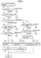
- Fig. 3 is a flowchart showing steps of a hill hold control of an automatic transmission of Fig. 1.
- a step S1 it is judged whether or not a vehicle travels on a grade. This judgment can be made by a known method. For example, whether or not a vehicle travels on a grade is judged based on respective detecting signals from a gear shift position sensor 46, a vehicle speed sensor 56, an acceleration sensor 57, an input and output shaft rotation speed sensor 55 and the like or the judgment is made based on a signal from an incline angle sensor.
- the shift gear train is a start gear train.
- the start gear train is either of shift gear trains, 1 st gear ratio, 2 nd gear ratio and reverse speed.
- the 1 st gear ratio or the 2 nd gear ratio are automatically selected according to the vehicle traveling situations.
- a shift gear train of reverse speed is selected.
- an engagement condition of the bypass clutch 29 is judged from a flag.
- the program goes to a step S4 where it is judged whether or not a foot brake is depressed by detecting an ON or OFF operation of the foot brake switch 49.
- the program goes to a step S5 where it is judged whether or not the vehicle stops or the vehicle is in standstill.
- the program goes to a step S6 where the bypass clutch 29 is engaged and at a step S7 a clutch flag F clutch is set to 1 (it means that bypass clutch is engaged).
- the hill hold routine has been executed and wheels are locked. For example, after the foot brake is depressed with the selector lever set to "D" range and the vehicle stops on a grade, even when the driver takes his or her foot from the foot brake pedal, the wheels are locked by the hill hold control and the vehicle is held in standstill. Then, when the vehicle stops with a start gear train selected, the main clutch 15 is controlled in a released condition, unless the vehicle is equipped with an automatic stopping and starting system.
- the program goes to a step S10 where the bypass clutch 29 is released and at a step S11 the clutch flag is set to a released condition (0).
- the step S4 in case where it is judged that a foot brake is depressed, the step 12 is executed and the bypass clutch 29 is established to a partially engaged condition. In this case, the routine finishes without changing the clutch flag.
- the program goes to a step S8 where the state of the accelerator pedal is detected based on a signal from the accelerator pedal opening angle sensor 53.
- the program goes to the step S6 where the hill hold control is maintained and if it is judged that the accelerator pedal is open, the program goes to a step S9 where it is judged whether the vehicle stops or travels.
- the program goes to the step S10 and in case where it is judged that the vehicle is in standstill, the start routine is executed. That is, when the accelerator pedal is depressed while the vehicle is in standstill, the start routine is executed.
- Fig. 4 is a flowchart showing a start routine.
- a road surface gradient ⁇ of the grade is estimated.
- the road surface gradient ⁇ may be calculated from driving force and vehicle speed or may be calculated by a signal from the incline angle sensor.
- an engine output torque is calculated based on signal from an engine speed sensor and the like according to a known method.
- the program goes to S16 where the condition of engagement of the main clutch, namely, the clutch stroke is detected based on a signal of the main clutch sensor 47 and at a step S17 an output torque T out of the automatic transmission is calculated based on the engine output torque obtained at the step S15, the engagement condition of the main clutch obtained at the step S16 and the gear ratio detected by the gear shift position sensor 46.
- the start torque T st calculated at the step S14 is compared with the output torque T out calculated at the step S17. If the output torque T st is larger than Tout, it is judged that the vehicle can start and if not it is judged that the vehicle can not start. In case where the vehicle can start, at a step S19, a hydraulic pressure P bd necessary for releasing the bypass clutch is calculated.
- a calorific value Q of the bypass clutch 29 is estimated and at a step S21 the calorific value Q is compared with a seizure limit calorific value of the bypass clutch 29 which is stored in the memory.
- the seizure limit calorific value is determined by experiments beforehand. In case where it is judged that the calorific value Q is within an allowable range, the program goes to a step S22. On the other hand, in case where it is judged that the calorific value Q is too much, the program goes to a step S23 where a reduction of engine output is required to the engine control unit. Then, at a step S22 hydraulic pressure of the bypass clutch 29 is outputted to the control unit. Thus, in case where there is fear of seizure in the bypass clutch 29, the engine output gradually goes down to prevent seizure.
- the calorific value Q becomes larger as the required hydraulic pressure is large, that is, the gradient is large. Further, the calorific value Q becomes larger with an increase of the number of rotation difference of the bypass clutch. In case of an excessive calorific value Q, the requirement of torque reduction continues to be issued and as a result the vehicle can not start. However, this is a very rare case in which the gradient exceeds far away 30 %.
- a greatest feature of the hill hold apparatus according to the present invention is that a hill hold can be realized only by hydraulically controlling an existing bypass clutch 29. Therefore, the hill hold apparatus does not require to incorporate any special devices such as brake piping, an accumulator and the like. Further, since the hill hold apparatus according to the present invention can perform a hill hold control based on road conditions, the vehicle can start smoothly without stepping back on a grade. Further, since the hill hold apparatus can start the vehicle within an allowable limit of calorific value of the bypass clutch, the drive train is prevented from being damaged by overloads.
- Fig. 5 is a flowchart showing steps of a hill hold control according to another embodiment. Since steps S31 to S42 of Fig. 5 correspond to steps S1 to S12 of Fig. 3, respectively, descriptions of respective steps S31 to S42 are omitted.
- a step S38 it is judged that the accelerator pedal is closed, the program goes to a step S43 where it is judged whether or not the parking brake is operative. If it is judged that the parking brake is operative, the program goes to a step S44 where it is judged whether or not the vehicle is in standstill. In case where it is judged that the vehicle is in standstill, at a step S42, the bypass clutch 29 is set to a partially engaged condition. After that, the program leaves the routine without changing the clutch flag.
- the program goes to a step S36 where the bypass clutch is set to an engaged condition.
- the hill hold control is available with the bypass clutch 29 partially engaged.
- the start routine shown in Fig. 4 is carried out.
- the control method shown in Fig. 5 when the parking brake is operative, since the bypass clutch can be partially engaged, the working pressure of the bypass clutch 29 can be reduced and as a result fuel consumption can be saved.
Landscapes
- Engineering & Computer Science (AREA)
- General Engineering & Computer Science (AREA)
- Mechanical Engineering (AREA)
- Control Of Transmission Device (AREA)
- Control Of Driving Devices And Active Controlling Of Vehicle (AREA)
- Control Of Vehicle Engines Or Engines For Specific Uses (AREA)
- Regulating Braking Force (AREA)
Abstract
Description
- The present invention relates to a hill hold control apparatus for a vehicle and more particularly to a hill hold control apparatus capable of locking wheels when a selector lever of an automatic transmission is positioned at "forward or reverse drive" range.
- JP-A-2000-65199 discloses an automatic transmission for an automobile comprising an input shaft having a plurality of drive gears, an output shaft having a plurality of driven gears paired with respective drive gears and a bypass clutch for engaging the input shaft with the output shaft. This type of automatic transmission has an advantage in that the rotation speed of the output shaft can be synchronized with the engine speed and shift shocks at up-shifting can be reduced by preventing so-called "torque drop" by transmitting torque through the bypass clutch in high speed shift stages. However, this type automatic transmission, in case where a friction clutch is used as a start clutch for engaging a crank shaft with the input shaft, has a problem that when the vehicle attempts to start forward on a grade, the vehicle reverses , while a driver shifts his or her foot from a brake pedal to an accelerator pedal and the friction clutch which has been released at stopping is engaged again.
- On the other hand, automatic transmissions of normal torque converter type having planetary gears generate creep torque. If a vehicle stops on a steep grade, creep torque can not hold the vehicle at a standstill and the vehicle reverses. Japanese Patent Application Laid-open No. Toku-Kai 2000-127928 discloses a hill hold control apparatus capable of locking wheels by a brake system when the select lever of an automatic transmission is selected at a forward drive position and specified conditions are satisfied. However, this hill hold apparatus needs to incorporate an accumulator and an electromagnetic operative opening and closing valve in the apparatus, this leading to an increase of the number of components and manufacturing cost.
- It is an object of the present invention to provide a hill hold control apparatus for a vehicle capable of performing a hill hold control easily by utilizing a bypass clutch provided between an input shaft and an output shaft of an automatic transmission.
- To achieve the object, a hill hold control apparatus comprises a grade judging means for judging that the vehicle travels on a grade, a shift gear train detecting means for detecting a shift gear train of the automatic transmission, a foot brake operation detecting means for detecting an operation of a foot brake, a first control means for partially engaging the bypass clutch when it is judged that the vehicle is in standstill and the shift gear train is a start gear train and the foot brake is operative based on respective signals of the grade, the shift gear train and the operation of the foot brake and a second control means for engaging the bypass clutch when it is judged that the vehicle is in standstill and the shift gear train is a start gear train and the foot brake is inoperative based on respective signals of the grade, the shift gear train and the operation of the foot brake.
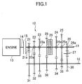
- Fig. 1 is a skeleton diagram showing an automatic transmission having a hill hold apparatus according to the present invention;
- Fig. 2 is a block diagram showing a control circuit for controlling an engine and an automatic transmission shown in Fig. 1;
- Fig. 3 is a flowchart showing a hill hold routine according to an embodiment of the present invention;
- Fig. 4 is a flowchart showing a start routine; and
- Fig. 5 is a flowchart showing a hill hold routine according to another embodiment of the present invention.
-
- Referring now to Fig. 1,
reference numeral 10 denotes an automatic transmission having aninput shaft 11 and anoutput shaft 12. There is provided a main clutch ( start clutch) 15 between acrankshaft 14 of anengine 13 and aninput shaft 11. When themain clutch 15 is engaged, the rotation of thecrankshaft 14 is transmitted to theinput shaft 11 and when themain clutch 15 is released, the power transmission stops. Themain clutch 15 is driven by a hydraulically operated actuator. -
Drive gears 21 to 25 for the 1st gear ratio to the 5th gear ratio respectively are mounted on theinput shaft 11 and drivengears 31 to 35 for the 1st gear ratio to the 5th gear ratio respectively are mounted on theoutput shaft 12. The respective drivengears 31 to 35 mesh with therespective drive gears 21 to 25, constituting respective shift gear trains from 1st to 5th gear ratios. Further, adrive gear 26 for reverse speed is mounted on theinput shaft 11 and meshes with a drivengear 36 which is mounted on theoutput shaft 12 through anidle gear 27. Thesedrive gear 26, drivengear 36 andidle gear 27 constitute a reverse gear train. In order to change over the shift gear trains for transmitting rotation from theinput shaft 11 to theoutput shaft 12, there are provideddog clutches 21a to 26a for therespective drive gears 21 to 26 on theinput shaft 11. - For example, when the
dog clutch 21a is engaged, the rotation of theinput shaft 11 is transmitted to theoutput shaft 12 through the shift gear train of thedrive gear 21 and the drivengear 31. With respect to other shift gear trains, similarly, when a dog clutch is engaged, a required shift gear train is selected. In place of the dog clutches, wet multiple disc clutches may be used or synchromesh mechanisms may be employed. Further, respective changeover mechanisms may be provided on theoutput shaft 12 or may be provided both on the input andoutput shafts - A drive
side bypass gear 28 is rotatably mounted on theinput shaft 11 and a drivenside bypass gear 38 meshing with thebypass gear 28 is fixed to theoutput shaft 12. Further, a bypass clutch (auxiliary clutch) 29 is mounted on theinput shaft 11. Thebypass clutch 29 is a wet type multiple disc clutch which can be operated in an engagement condition, in a partially engaged condition and in a released condition. Thisbypass clutch 29 can prevent "torque drop" at shifting by being engaged when the gear is up-shifted. Thisbypass clutch 29 may mounted on theoutput shaft 12 or may be mounted on an intermediate shaft other than the input andoutput shafts bypass clutch 29 is actuated by an hydraulically operated actuator. - In the
automatic transmission 10 having thebypass clutch 29, using thebypass clutch 29 for originally preventing "torque drop" at shifting, a hill hold control can be performed by engaging thebypass clutch 29 on a grade. For example, when a vehicle is in standstill on an upgrade, the gear train of the 1st gear ratio is in a power transmitting condition and at the same time thebypass clutch 29 is engaged. As a result, since the gear ratio of the gear train composed of thegears bypass gears input shaft 11 and theoutput shaft 12 and as a result the wheels are locked. The shift gear train used when the hill hold control is performed may be a gear train for the 1st gear ratio or a gear train for the 2nd gear ratio. - As described above, since the
bypass clutch 29 is operated by hydraulic pressure fed from the actuator, the hill hold control can be performed by electronically detecting the selected shift gear train of the 1st gear ratio, 2nd gear ratio or reverse speed and controlling a hydraulic pressure to the actuator. Thus, since the hill hold control is assisted by an electronic control, by releasing thebypass clutch 29 according to the positions of the shift gear trains and operations of miscellaneous pedals, the vehicle can roll forward or rearward freely and by calculating a gradient angle of the vehicle or output torque, the vehicle can start smoothly. - Referring to Fig. 2,
reference numeral 40 denotes a control unit having a CPU and memories. Thecontrol unit 40 sends control signals to amain clutch actuator 41 for actuating themain clutch 15, agear shift actuator 42 for changing over the shift gear train by actuating thedog clutches 21a to 26a, abypass clutch actuator 43 for actuating thebypass clutch 29. Working fluid is supplied from a hydraulic pump driven by apump drive motor 44 to theseactuators 41 to 43. Thepump drive motor 44 is controlled by signals from thecontrol unit 40. The pressure of working fluid discharged from the hydraulic pump is detected by ahydraulic pressure sensor 45. The gear shift position (gear train position) is detected by a gearshift position sensor 46. The clutch stroke of themain clutch 15 is detected by amain clutch sensor 47. Signals from the respective sensors are sent to thecontrol unit 40. The hydraulic pump may be driven by an engine not by themotor 44. - When a driver operates a selector lever, miscellaneous ranges such as Drive "D" range and Reverse "R" range are selected . There is provided a selector
lever position sensor 48 for detecting a selected range and there is provided afoot brake switch 49 for detecting whether or not a foot brake has been operated by the driver. Further, there is provided aparking brake switch 50 for detecting whether or not a parking brake has been operated. Respective detecting signals are sent to thecontrol unit 40. - When an ignition key is operated, an
ignition key switch 51 sends a signal to thecontrol unit 40. Thecontrol unit 40 sends an operating signal to astarter motor 52. A signal from an accelerator pedalopening angle sensor 53 for detecting the depressing amount of an accelerator pedal is sent to thecontrol unit 40. Thecontrol unit 40 sends a control signal to an electronic throttle valve control apparatus (ETC) 54. Further, thecontrol unit 40 receives detecting signals from an input and outputshaft speed sensor 55 for detecting the revolution speed of the input and output shafts, from avehicle speed sensor 56 for detecting vehicle speeds and from anacceleration sensor 57 for detecting lateral acceleration of the vehicle. - Fig. 3 is a flowchart showing steps of a hill hold control of an automatic transmission of Fig. 1. In the drawing, at a step S1, it is judged whether or not a vehicle travels on a grade. This judgment can be made by a known method. For example, whether or not a vehicle travels on a grade is judged based on respective detecting signals from a gear
shift position sensor 46, avehicle speed sensor 56, anacceleration sensor 57, an input and output shaftrotation speed sensor 55 and the like or the judgment is made based on a signal from an incline angle sensor. - When it is judged that the vehicle travels on a grade, at a step S2, it is judged whether or not the shift gear train is a start gear train. The start gear train is either of shift gear trains, 1st gear ratio, 2nd gear ratio and reverse speed. When a driver shifts the selector lever to "D" range, the 1st gear ratio or the 2nd gear ratio are automatically selected according to the vehicle traveling situations. When the driver shifts the selector lever to "R" range, a shift gear train of reverse speed is selected.
- At a step S3, an engagement condition of the
bypass clutch 29 is judged from a flag. In case where it is judged at the step S3 that a clutch flag is 0, namely, thebypass clutch 29 is in a released condition, the program goes to a step S4 where it is judged whether or not a foot brake is depressed by detecting an ON or OFF operation of thefoot brake switch 49. When it is judged at the step S4 that the foot brake is not depressed, the program goes to a step S5 where it is judged whether or not the vehicle stops or the vehicle is in standstill. In case where it is judged that the vehicle stops, the program goes to a step S6 where thebypass clutch 29 is engaged and at a step S7 a clutch flag Fclutch is set to 1 (it means that bypass clutch is engaged). Thus , the hill hold routine has been executed and wheels are locked. For example, after the foot brake is depressed with the selector lever set to "D" range and the vehicle stops on a grade, even when the driver takes his or her foot from the foot brake pedal, the wheels are locked by the hill hold control and the vehicle is held in standstill. Then, when the vehicle stops with a start gear train selected, the main clutch 15 is controlled in a released condition, unless the vehicle is equipped with an automatic stopping and starting system. - In case where it is judged at the step S1 that the vehicle travels on a level road, in case where it is judged at the step S2 that a gear train other than the start gear train is selected or in case where it is judged at the step S5 that the vehicle is traveling, the program goes to a step S10 where the
bypass clutch 29 is released and at a step S11 the clutch flag is set to a released condition (0). On the other hand, at the step S4, in case where it is judged that a foot brake is depressed, thestep 12 is executed and thebypass clutch 29 is established to a partially engaged condition. In this case, the routine finishes without changing the clutch flag. Thus, when it is judged at the step S4 that the foot brake pedal is depressed, since thebypass clutch 29 is partially engaged, thebypass clutch 29 can be engaged swiftly, when the depression of the foot brake pedal is released. - On the other hand, in case where it is judged at the step S3 that the
bypass clutch 29 is in an engaged condition, the program goes to a step S8 where the state of the accelerator pedal is detected based on a signal from the accelerator pedalopening angle sensor 53. At the step S8, if it is judged that the accelerator pedal is closed, the program goes to the step S6 where the hill hold control is maintained and if it is judged that the accelerator pedal is open, the program goes to a step S9 where it is judged whether the vehicle stops or travels. At the step S9, in case where it is judged that the vehicle is not in standstill, the program goes to the step S10 and in case where it is judged that the vehicle is in standstill, the start routine is executed. That is, when the accelerator pedal is depressed while the vehicle is in standstill, the start routine is executed. - Fig. 4 is a flowchart showing a start routine. When the start routine is carried out, first at a step S13, a road surface gradient of the grade is estimated. The road surface gradient may be calculated from driving force and vehicle speed or may be calculated by a signal from the incline angle sensor. At a step S14, a start torque Tst necessary for starting is calculated according to the following formula (1):
- It is understood from this formula that the start torque Tst increases as the road surface gradient increases.
- Next, at a step S15, an engine output torque is calculated based on signal from an engine speed sensor and the like according to a known method. Then, the program goes to S16 where the condition of engagement of the main clutch, namely, the clutch stroke is detected based on a signal of the main
clutch sensor 47 and at a step S17 an output torque Tout of the automatic transmission is calculated based on the engine output torque obtained at the step S15, the engagement condition of the main clutch obtained at the step S16 and the gear ratio detected by the gearshift position sensor 46. - Next, at a step S18, the start torque Tst calculated at the step S14 is compared with the output torque Tout calculated at the step S17. If the output torque Tst is larger than Tout, it is judged that the vehicle can start and if not it is judged that the vehicle can not start. In case where the vehicle can start, at a step S19, a hydraulic pressure Pbd necessary for releasing the bypass clutch is calculated. The hydraulic pressure value Pbd is calculated according to the following formulas (2), (3) and (4):
bypass clutch 29; Kv is gain coefficient and is determined from a table parameterizing vehicle speed; N is pressure of clutch facing of thebypass clutch 29; µb is friction coefficient of the clutch facing; Rbc is average effective radius of the clutch facing; Fs is spring load and Sb is area of clutch facing. - At a step S20, a calorific value Q of the
bypass clutch 29 is estimated and at a step S21 the calorific value Q is compared with a seizure limit calorific value of thebypass clutch 29 which is stored in the memory. The seizure limit calorific value is determined by experiments beforehand. In case where it is judged that the calorific value Q is within an allowable range, the program goes to a step S22. On the other hand, in case where it is judged that the calorific value Q is too much, the program goes to a step S23 where a reduction of engine output is required to the engine control unit. Then, at a step S22 hydraulic pressure of thebypass clutch 29 is outputted to the control unit. Thus, in case where there is fear of seizure in thebypass clutch 29, the engine output gradually goes down to prevent seizure. - The calorific value Q estimated at the step S20 is obtained from the following formula (5):
- The calorific value Q becomes larger as the required hydraulic pressure is large, that is, the gradient is large. Further, the calorific value Q becomes larger with an increase of the number of rotation difference of the bypass clutch. In case of an excessive calorific value Q, the requirement of torque reduction continues to be issued and as a result the vehicle can not start. However, this is a very rare case in which the gradient exceeds far away 30 %.
- A greatest feature of the hill hold apparatus according to the present invention is that a hill hold can be realized only by hydraulically controlling an existing
bypass clutch 29. Therefore, the hill hold apparatus does not require to incorporate any special devices such as brake piping, an accumulator and the like. Further, since the hill hold apparatus according to the present invention can perform a hill hold control based on road conditions, the vehicle can start smoothly without stepping back on a grade. Further, since the hill hold apparatus can start the vehicle within an allowable limit of calorific value of the bypass clutch, the drive train is prevented from being damaged by overloads. - Fig. 5 is a flowchart showing steps of a hill hold control according to another embodiment. Since steps S31 to S42 of Fig. 5 correspond to steps S1 to S12 of Fig. 3, respectively, descriptions of respective steps S31 to S42 are omitted. At a step S38, it is judged that the accelerator pedal is closed, the program goes to a step S43 where it is judged whether or not the parking brake is operative. If it is judged that the parking brake is operative, the program goes to a step S44 where it is judged whether or not the vehicle is in standstill. In case where it is judged that the vehicle is in standstill, at a step S42, the
bypass clutch 29 is set to a partially engaged condition. After that, the program leaves the routine without changing the clutch flag. At thestep 43, in case where it is judged that the parking brake is inoperative, or at a step S44 in case where it is judged that the vehicle is traveling, the program goes to a step S36 where the bypass clutch is set to an engaged condition. - According to the control method shown in Fig. 5, when the parking brake is operative, the hill hold control is available with the bypass clutch 29 partially engaged. As a result, it is possible to reduce a power for operating the
bypass clutch 29, this contributing to an improvement of fuel economy. When the accelerator pedal opens in a standstill of the vehicle, the start routine shown in Fig. 4 is carried out. According to the control method shown in Fig. 5, when the parking brake is operative, since the bypass clutch can be partially engaged, the working pressure of thebypass clutch 29 can be reduced and as a result fuel consumption can be saved. - While the present invention has been disclosed in terms of preferred embodiments in order to facilitate better understanding of the invention, it should be appreciated that the invention can be embodied in various ways without departing from the principle of the invention. Therefore, the invention should be understood to include all possible embodiments which can be embodied without departing from the principle of the invention set out in the appended claims.
Claims (6)
- A hill hold control apparatus of a vehicle having an automatic transmission including a plurality of drive gears mounted on an input shaft, a plurality of driven gears meshing with said drive gears and mounted on an output shaft and a bypass clutch for engaging said input shaft with said output shaft, comprising:a grade judging means for judging that said vehicle travels on a grade;a shift gear train detecting means for detecting a shift gear train of said automatic transmission; anda control means for engaging said bypass clutch when it is judged that said vehicle is in standstill and said shift gear train is a start gear train based on respective signals of said grade and shift gear train.
- A hill hold control apparatus of a vehicle having an automatic transmission including a plurality of drive gears mounted on an input shaft, a plurality of driven gears meshing with said drive gears and mounted on an output shaft and a bypass clutch for engaging said input shaft with said output shaft, comprising:a grade judging means for judging that said vehicle travels on a grade;a shift gear train detecting means for detecting a shift gear train of said automatic transmission;a foot brake operation detecting means for detecting an operation of a foot brake; anda control means for engaging said bypass clutch when it is judged that said vehicle is in standstill and said shift gear train is a start gear train and said foot brake is inoperative based on respective signals of said grade, said shift gear train and said operation of said foot brake.
- A hill hold control apparatus of a vehicle having an automatic transmission including a plurality of drive gears mounted on an input shaft, a plurality of driven gears meshing with said drive gears and mounted on an output shaft and a bypass clutch for engaging said input shaft with said output shaft, comprising:a grade judging means for judging that said vehicle travels on a grade;a shift gear train detecting means for detecting a shift gear train of said automatic transmission;a foot brake operation detecting means for detecting an operation of a foot brake;a first control means for partially engaging said bypass clutch when it is judged that said vehicle is in standstill and said shift gear train is a start gear train and said foot brake is operative based on respective signals of said grade, said shift gear train and said operation of said foot brake; anda second control means for engaging said bypass clutch when it is judged that said vehicle is in standstill and said shift gear train is a start gear train and said foot brake is inoperative based on respective signals of said grade, said shift gear train and said operation of said foot brake.
- A hill hold control apparatus of a vehicle having an automatic transmission including a plurality of drive gears mounted on an input shaft, a plurality of driven gears meshing with said drive gears and mounted on an output shaft and a bypass clutch for engaging said input shaft with said output shaft, comprising:a grade judging means for judging that said vehicle travels on a grade;a shift gear train detecting means for detecting a shift gear train of said automatic transmission;a parking brake operation detecting means for detecting an operation of a parking brake;a third control means for partially engaging said bypass clutch when it is judged that said vehicle is in standstill and said shift gear train is a start gear train and said parking brake is inoperative based on respective signals of said grade, said shift gear train and said operation of said parking brake; anda fourth control means for engaging said bypass clutch when it is judged that said vehicle is in standstill and said shift gear train is a start gear train and said parking brake is inoperative based on respective signals of said grade, said shift gear train and said operation of said parking brake.
- The apparatus according to claim 1, 2, 3 or 4, further comprising:a road gradient estimating means for estimating a road surface gradient of a road on which said vehicle travels;a start torque calculating means for calculating a start torque necessary for starting said vehicle based on said road surface gradient;an output torque calculating means for calculating an output torque based on an engine torque and an engagement condition of a main clutch; anda bypass clutch releasing means for releasing said bypass clutch when said output torque exceeds said start torque so as to start said vehicle.
- The apparatus according to any one of claims 1 to 5, further comprising:a calorific value calculating means for calculating a calorific value of said bypass clutch; andan engine power reducing means for reducing an engine power when said calorific value exceeds a threshold value.
Applications Claiming Priority (2)
| Application Number | Priority Date | Filing Date | Title |
|---|---|---|---|
| JP2000360516 | 2000-11-28 | ||
| JP2000360516A JP2002168333A (en) | 2000-11-28 | 2000-11-28 | Hill-hold control device of automobile |
Publications (3)
| Publication Number | Publication Date |
|---|---|
| EP1223368A2 true EP1223368A2 (en) | 2002-07-17 |
| EP1223368A3 EP1223368A3 (en) | 2004-08-11 |
| EP1223368B1 EP1223368B1 (en) | 2006-04-19 |
Family
ID=18832101
Family Applications (1)
| Application Number | Title | Priority Date | Filing Date |
|---|---|---|---|
| EP01128243A Expired - Lifetime EP1223368B1 (en) | 2000-11-28 | 2001-11-28 | Hill hold control apparatus for vehicle |
Country Status (4)
| Country | Link |
|---|---|
| US (1) | US6616572B2 (en) |
| EP (1) | EP1223368B1 (en) |
| JP (1) | JP2002168333A (en) |
| DE (1) | DE60118875T2 (en) |
Cited By (4)
| Publication number | Priority date | Publication date | Assignee | Title |
|---|---|---|---|---|
| EP1350663A1 (en) * | 2002-04-03 | 2003-10-08 | Peugeot Citroen Automobiles SA | Hill hold control method for vehicle equipped with an automatic clutch |
| DE10320775A1 (en) * | 2003-05-09 | 2004-12-02 | Zf Friedrichshafen Ag | Controlling automatic gearbox with clutch and several shift elements involves controlling clutch and shift elements so braking torque generated at drive output with rolling away prevention activated |
| DE102004013430B4 (en) * | 2003-03-19 | 2007-04-26 | Suzuki Motor Corp., Hamamatsu | Control device for automatic transmissions for motor vehicles |
| US7392627B2 (en) | 2004-01-16 | 2008-07-01 | Hermann Friedrich Kuenne Gmbh & Co. | Profiled rail system for bridging floorcovering transitions |
Families Citing this family (31)
| Publication number | Priority date | Publication date | Assignee | Title |
|---|---|---|---|---|
| EP1443248B1 (en) * | 2001-11-08 | 2009-01-14 | Hitachi, Ltd. | Gear transmission with a control device |
| JP3612711B2 (en) * | 2002-07-03 | 2005-01-19 | トヨタ自動車株式会社 | Automobile |
| JP4621969B2 (en) * | 2004-05-28 | 2011-02-02 | スズキ株式会社 | Control device for automatic transmission |
| DE102005001550A1 (en) * | 2005-01-13 | 2006-07-27 | Zf Friedrichshafen Ag | Method for starting control of a motor vehicle |
| US7166060B2 (en) * | 2005-01-18 | 2007-01-23 | Ford Global Technologies, Llc. | Hill hold for a vehicle |
| US7509202B2 (en) * | 2006-01-17 | 2009-03-24 | General Motors Corporation | Neutral idle hill detection |
| US7853388B2 (en) * | 2006-02-23 | 2010-12-14 | Siemens Industry, Inc. | Devices, systems, and methods for controlling a braking system |
| US8620498B2 (en) * | 2006-06-20 | 2013-12-31 | GM Global Technology Operations LLC | Hybrid road grade determination system |
| JP4127310B2 (en) * | 2006-12-27 | 2008-07-30 | トヨタ自動車株式会社 | Vehicle control device, control method, program for realizing the method, and recording medium recording the program |
| JP2008309267A (en) * | 2007-06-15 | 2008-12-25 | Jatco Ltd | Control device for automatic transmission |
| FR2921882B1 (en) * | 2007-10-03 | 2009-12-04 | Renault Sas | ASSISTING DEVICE FOR MANEUVERING THE RISE OF A SLOPE OF A MOTOR VEHICLE |
| DE102007055085B4 (en) * | 2007-11-16 | 2019-02-21 | Getrag-Ford Transmissions Gmbh | Method for preventing uncontrolled rollback |
| JP4957528B2 (en) * | 2007-12-03 | 2012-06-20 | 日産自動車株式会社 | High response start control device for vehicle equipped with transmission with capacity controlled start clutch |
| US20090187324A1 (en) * | 2008-01-23 | 2009-07-23 | Jianbo Lu | Vehicle Stability Control System and Method |
| JP5272654B2 (en) * | 2008-10-30 | 2013-08-28 | 井関農機株式会社 | Tractor travel transmission |
| US8880288B2 (en) * | 2009-06-16 | 2014-11-04 | Robert Bosch Gmbh | Determining low-speed driving direction in a vehicle |
| DE102010003510B4 (en) * | 2010-03-31 | 2022-11-17 | Zf Friedrichshafen Ag | Method of operating a power train |
| JP5700779B2 (en) * | 2010-11-24 | 2015-04-15 | Udトラックス株式会社 | Vehicle start control system |
| DE102013000838A1 (en) * | 2013-01-21 | 2014-07-24 | Getrag Getriebe- Und Zahnradfabrik Hermann Hagenmeyer Gmbh & Cie Kg | Method for holding a motor vehicle on a slope |
| US9126597B2 (en) | 2013-03-14 | 2015-09-08 | Robert Bosch Gmbh | Hill hold decay |
| GB2525595B (en) * | 2014-04-28 | 2016-12-14 | Caterpillar Sarl | Braking system and method for machine |
| JP2016061409A (en) * | 2014-09-19 | 2016-04-25 | アイシン精機株式会社 | Hill hold device and hill holding method |
| US9995391B2 (en) * | 2015-09-24 | 2018-06-12 | Hyundai Motor Company | Control method for preventing backward slipping of vehicle |
| DE102016202693A1 (en) | 2016-02-22 | 2017-08-24 | Audi Ag | Protective device for a drive train of a motor vehicle |
| US9821778B2 (en) | 2016-02-23 | 2017-11-21 | Honda Motor Co., Ltd. | Vehicle control system |
| US9809207B2 (en) | 2016-02-23 | 2017-11-07 | Honda Motor Co., Ltd. | Vehicle control system |
| CN107618522B (en) * | 2017-09-12 | 2020-03-17 | 中国神华能源股份有限公司 | Train limited ramp starting operation prompt system |
| DE102018206204B4 (en) * | 2018-04-23 | 2021-05-06 | Zf Friedrichshafen Ag | Method of holding a vehicle on a hill |
| US10670142B1 (en) * | 2018-11-19 | 2020-06-02 | Schaeffler Technologies AG & Co. KG | Hybrid module including a torque converter bypass clutch |
| JP7347365B2 (en) * | 2020-08-06 | 2023-09-20 | トヨタ自動車株式会社 | Heat load estimation device for frictional engagement elements |
| CN112943915B (en) * | 2021-03-19 | 2022-08-23 | 潍柴动力股份有限公司 | Hill starting control method and vehicle |
Citations (3)
| Publication number | Priority date | Publication date | Assignee | Title |
|---|---|---|---|---|
| EP0367020A1 (en) * | 1988-10-31 | 1990-05-09 | Volkswagen Aktiengesellschaft | Method for gear shift of a change speed gear |
| DE4316784A1 (en) * | 1993-05-19 | 1994-11-24 | Getrag Getriebe Zahnrad | Drive unit for motor vehicles |
| EP0681123A2 (en) * | 1994-05-02 | 1995-11-08 | Aisin Aw Co., Ltd. | Control method and control system for automatic transmission |
Family Cites Families (7)
| Publication number | Priority date | Publication date | Assignee | Title |
|---|---|---|---|---|
| US5172797A (en) * | 1992-01-24 | 1992-12-22 | Eaton Corporation | Motor vehicle inertia and hill holding braking mechanism |
| KR970046648A (en) * | 1995-12-19 | 1997-07-26 | 전성원 | Semi-automatic shift control device with slope shift prevention function and method |
| JP3039367B2 (en) * | 1996-03-27 | 2000-05-08 | アイシン・エィ・ダブリュ株式会社 | Control device for automatic transmission |
| JP3601276B2 (en) * | 1997-12-08 | 2004-12-15 | アイシン・エィ・ダブリュ株式会社 | Control device for automatic transmission |
| US5943911A (en) * | 1998-05-11 | 1999-08-31 | Borg-Warner Automotive, Inc. | Electromechanical friction clutch control for a manual transmission |
| JP2000065199A (en) | 1998-08-12 | 2000-03-03 | Hitachi Ltd | Control device and control method for automatic transmission |
| JP2000127928A (en) | 1998-10-22 | 2000-05-09 | Toyota Motor Corp | Hill hold control device for vehicle |
-
2000
- 2000-11-28 JP JP2000360516A patent/JP2002168333A/en active Pending
-
2001
- 2001-11-27 US US09/994,018 patent/US6616572B2/en not_active Expired - Fee Related
- 2001-11-28 DE DE60118875T patent/DE60118875T2/en not_active Expired - Fee Related
- 2001-11-28 EP EP01128243A patent/EP1223368B1/en not_active Expired - Lifetime
Patent Citations (3)
| Publication number | Priority date | Publication date | Assignee | Title |
|---|---|---|---|---|
| EP0367020A1 (en) * | 1988-10-31 | 1990-05-09 | Volkswagen Aktiengesellschaft | Method for gear shift of a change speed gear |
| DE4316784A1 (en) * | 1993-05-19 | 1994-11-24 | Getrag Getriebe Zahnrad | Drive unit for motor vehicles |
| EP0681123A2 (en) * | 1994-05-02 | 1995-11-08 | Aisin Aw Co., Ltd. | Control method and control system for automatic transmission |
Non-Patent Citations (1)
| Title |
|---|
| PATENT ABSTRACTS OF JAPAN vol. 0152, no. 79 (M-1136), 16 July 1991 (1991-07-16) & JP 3 096760 A (NISSAN MOTOR CO LTD), 22 April 1991 (1991-04-22) * |
Cited By (4)
| Publication number | Priority date | Publication date | Assignee | Title |
|---|---|---|---|---|
| EP1350663A1 (en) * | 2002-04-03 | 2003-10-08 | Peugeot Citroen Automobiles SA | Hill hold control method for vehicle equipped with an automatic clutch |
| DE102004013430B4 (en) * | 2003-03-19 | 2007-04-26 | Suzuki Motor Corp., Hamamatsu | Control device for automatic transmissions for motor vehicles |
| DE10320775A1 (en) * | 2003-05-09 | 2004-12-02 | Zf Friedrichshafen Ag | Controlling automatic gearbox with clutch and several shift elements involves controlling clutch and shift elements so braking torque generated at drive output with rolling away prevention activated |
| US7392627B2 (en) | 2004-01-16 | 2008-07-01 | Hermann Friedrich Kuenne Gmbh & Co. | Profiled rail system for bridging floorcovering transitions |
Also Published As
| Publication number | Publication date |
|---|---|
| US6616572B2 (en) | 2003-09-09 |
| EP1223368B1 (en) | 2006-04-19 |
| DE60118875D1 (en) | 2006-05-24 |
| DE60118875T2 (en) | 2006-09-07 |
| US20020065170A1 (en) | 2002-05-30 |
| JP2002168333A (en) | 2002-06-14 |
| EP1223368A3 (en) | 2004-08-11 |
Similar Documents
| Publication | Publication Date | Title |
|---|---|---|
| US6616572B2 (en) | Hill hold control apparatus for vehicle | |
| US6949051B2 (en) | Multistage automatic transmission | |
| US20070026996A1 (en) | Shift control apparartus and shift control method of automatic transmission of vehicle | |
| JP4663840B2 (en) | Engine overrun prevention device for automatic transmission | |
| US20030186779A1 (en) | Control apparatus for an automatic transmission and a method for controlling the same | |
| US7632210B2 (en) | Device and method for controlling an automatic transmission | |
| US5522779A (en) | Shift control system for automatic transmission | |
| JP3675341B2 (en) | Vehicle drive device | |
| EP1502804B1 (en) | Shift control apparatus for automatic transmission | |
| EP1310696B1 (en) | Automatic-clutch control system of automatic clutch type transmission | |
| EP1443248A1 (en) | Gear type speed change unit control device, control method, and automobile | |
| JPS6346303B2 (en) | ||
| JP5653694B2 (en) | Vehicle creep torque control device | |
| US6059681A (en) | Neutral control device of automatic transmission | |
| JP4100057B2 (en) | Shift control device | |
| JP4706138B2 (en) | Vehicle slope start assist device | |
| JP4042290B2 (en) | Automatic clutch creep control device | |
| JP3797220B2 (en) | Automatic transmission for vehicle | |
| JP4415291B2 (en) | Automatic transmission for vehicle | |
| JP3893842B2 (en) | Vehicle auto clutch control device | |
| JP4075671B2 (en) | Vehicle control device | |
| JP2979448B2 (en) | Control device for automatic transmission for vehicles | |
| JP4122668B2 (en) | Shift control device for automatic transmission | |
| JP3619854B2 (en) | Shift control method for automatic transmission for vehicle | |
| JP3622355B2 (en) | Control device for automatic transmission |
Legal Events
| Date | Code | Title | Description |
|---|---|---|---|
| PUAI | Public reference made under article 153(3) epc to a published international application that has entered the european phase |
Free format text: ORIGINAL CODE: 0009012 |
|
| AK | Designated contracting states |
Kind code of ref document: A2 Designated state(s): AT BE CH CY DE DK ES FI FR GB GR IE IT LI LU MC NL PT SE TR |
|
| AX | Request for extension of the european patent |
Free format text: AL;LT;LV;MK;RO;SI |
|
| PUAL | Search report despatched |
Free format text: ORIGINAL CODE: 0009013 |
|
| AK | Designated contracting states |
Kind code of ref document: A3 Designated state(s): AT BE CH CY DE DK ES FI FR GB GR IE IT LI LU MC NL PT SE TR |
|
| AX | Request for extension of the european patent |
Extension state: AL LT LV MK RO SI |
|
| 17P | Request for examination filed |
Effective date: 20041029 |
|
| 17Q | First examination report despatched |
Effective date: 20050321 |
|
| AKX | Designation fees paid |
Designated state(s): DE GB |
|
| GRAP | Despatch of communication of intention to grant a patent |
Free format text: ORIGINAL CODE: EPIDOSNIGR1 |
|
| GRAS | Grant fee paid |
Free format text: ORIGINAL CODE: EPIDOSNIGR3 |
|
| GRAA | (expected) grant |
Free format text: ORIGINAL CODE: 0009210 |
|
| RAP1 | Party data changed (applicant data changed or rights of an application transferred) |
Owner name: FUJI JUKOGYO KABUSHIKI KAISHA |
|
| AK | Designated contracting states |
Kind code of ref document: B1 Designated state(s): DE GB |
|
| REG | Reference to a national code |
Ref country code: GB Ref legal event code: FG4D |
|
| REF | Corresponds to: |
Ref document number: 60118875 Country of ref document: DE Date of ref document: 20060524 Kind code of ref document: P |
|
| PLBE | No opposition filed within time limit |
Free format text: ORIGINAL CODE: 0009261 |
|
| STAA | Information on the status of an ep patent application or granted ep patent |
Free format text: STATUS: NO OPPOSITION FILED WITHIN TIME LIMIT |
|
| 26N | No opposition filed |
Effective date: 20070122 |
|
| GBPC | Gb: european patent ceased through non-payment of renewal fee |
Effective date: 20061128 |
|
| PG25 | Lapsed in a contracting state [announced via postgrant information from national office to epo] |
Ref country code: GB Free format text: LAPSE BECAUSE OF NON-PAYMENT OF DUE FEES Effective date: 20061128 |
|
| PGFP | Annual fee paid to national office [announced via postgrant information from national office to epo] |
Ref country code: DE Payment date: 20081120 Year of fee payment: 8 |
|
| PG25 | Lapsed in a contracting state [announced via postgrant information from national office to epo] |
Ref country code: DE Free format text: LAPSE BECAUSE OF NON-PAYMENT OF DUE FEES Effective date: 20100601 |