EP1222902B1 - Intraokuläre Linsen - Google Patents
Intraokuläre Linsen Download PDFInfo
- Publication number
- EP1222902B1 EP1222902B1 EP01402543A EP01402543A EP1222902B1 EP 1222902 B1 EP1222902 B1 EP 1222902B1 EP 01402543 A EP01402543 A EP 01402543A EP 01402543 A EP01402543 A EP 01402543A EP 1222902 B1 EP1222902 B1 EP 1222902B1
- Authority
- EP
- European Patent Office
- Prior art keywords
- optical
- intraocular lens
- legs
- loop
- optical part
- Prior art date
- Legal status (The legal status is an assumption and is not a legal conclusion. Google has not performed a legal analysis and makes no representation as to the accuracy of the status listed.)
- Expired - Lifetime
Links
- 230000003287 optical effect Effects 0.000 claims abstract description 76
- 239000000463 material Substances 0.000 claims description 5
- 230000001154 acute effect Effects 0.000 claims description 2
- 210000000695 crystalline len Anatomy 0.000 description 62
- 230000006835 compression Effects 0.000 description 8
- 238000007906 compression Methods 0.000 description 8
- 238000005452 bending Methods 0.000 description 7
- 239000007943 implant Substances 0.000 description 6
- 238000003780 insertion Methods 0.000 description 4
- 230000037431 insertion Effects 0.000 description 4
- 208000002177 Cataract Diseases 0.000 description 3
- 238000009825 accumulation Methods 0.000 description 3
- 230000002093 peripheral effect Effects 0.000 description 3
- 239000002775 capsule Substances 0.000 description 2
- 238000006073 displacement reaction Methods 0.000 description 2
- 238000012423 maintenance Methods 0.000 description 2
- 229920003229 poly(methyl methacrylate) Polymers 0.000 description 2
- 239000004926 polymethyl methacrylate Substances 0.000 description 2
- 206010002945 Aphakia Diseases 0.000 description 1
- 201000004569 Blindness Diseases 0.000 description 1
- 208000008516 Capsule Opacification Diseases 0.000 description 1
- 208000035965 Postoperative Complications Diseases 0.000 description 1
- NIXOWILDQLNWCW-UHFFFAOYSA-N acrylic acid group Chemical group C(C=C)(=O)O NIXOWILDQLNWCW-UHFFFAOYSA-N 0.000 description 1
- 230000002411 adverse Effects 0.000 description 1
- 210000002159 anterior chamber Anatomy 0.000 description 1
- 201000009310 astigmatism Diseases 0.000 description 1
- 230000005540 biological transmission Effects 0.000 description 1
- 230000010261 cell growth Effects 0.000 description 1
- 230000001886 ciliary effect Effects 0.000 description 1
- 238000012937 correction Methods 0.000 description 1
- 238000011161 development Methods 0.000 description 1
- 230000018109 developmental process Effects 0.000 description 1
- 230000000694 effects Effects 0.000 description 1
- 238000000605 extraction Methods 0.000 description 1
- 230000002209 hydrophobic effect Effects 0.000 description 1
- 208000018769 loss of vision Diseases 0.000 description 1
- 231100000864 loss of vision Toxicity 0.000 description 1
- 238000003754 machining Methods 0.000 description 1
- 238000000034 method Methods 0.000 description 1
- 229920000642 polymer Polymers 0.000 description 1
- 229920001296 polysiloxane Polymers 0.000 description 1
- -1 polysiloxanes Polymers 0.000 description 1
- 230000000750 progressive effect Effects 0.000 description 1
- 208000014733 refractive error Diseases 0.000 description 1
- 230000035945 sensitivity Effects 0.000 description 1
- 230000004393 visual impairment Effects 0.000 description 1
Images

Classifications
-
- A—HUMAN NECESSITIES
- A61—MEDICAL OR VETERINARY SCIENCE; HYGIENE
- A61F—FILTERS IMPLANTABLE INTO BLOOD VESSELS; PROSTHESES; DEVICES PROVIDING PATENCY TO, OR PREVENTING COLLAPSING OF, TUBULAR STRUCTURES OF THE BODY, e.g. STENTS; ORTHOPAEDIC, NURSING OR CONTRACEPTIVE DEVICES; FOMENTATION; TREATMENT OR PROTECTION OF EYES OR EARS; BANDAGES, DRESSINGS OR ABSORBENT PADS; FIRST-AID KITS
- A61F2/00—Filters implantable into blood vessels; Prostheses, i.e. artificial substitutes or replacements for parts of the body; Appliances for connecting them with the body; Devices providing patency to, or preventing collapsing of, tubular structures of the body, e.g. stents
- A61F2/02—Prostheses implantable into the body
- A61F2/14—Eye parts, e.g. lenses or corneal implants; Artificial eyes
- A61F2/16—Intraocular lenses
- A61F2/1613—Intraocular lenses having special lens configurations, e.g. multipart lenses; having particular optical properties, e.g. pseudo-accommodative lenses, lenses having aberration corrections, diffractive lenses, lenses for variably absorbing electromagnetic radiation, lenses having variable focus
- A61F2/1616—Pseudo-accommodative, e.g. multifocal or enabling monovision
-
- A—HUMAN NECESSITIES
- A61—MEDICAL OR VETERINARY SCIENCE; HYGIENE
- A61F—FILTERS IMPLANTABLE INTO BLOOD VESSELS; PROSTHESES; DEVICES PROVIDING PATENCY TO, OR PREVENTING COLLAPSING OF, TUBULAR STRUCTURES OF THE BODY, e.g. STENTS; ORTHOPAEDIC, NURSING OR CONTRACEPTIVE DEVICES; FOMENTATION; TREATMENT OR PROTECTION OF EYES OR EARS; BANDAGES, DRESSINGS OR ABSORBENT PADS; FIRST-AID KITS
- A61F2/00—Filters implantable into blood vessels; Prostheses, i.e. artificial substitutes or replacements for parts of the body; Appliances for connecting them with the body; Devices providing patency to, or preventing collapsing of, tubular structures of the body, e.g. stents
- A61F2/02—Prostheses implantable into the body
- A61F2/14—Eye parts, e.g. lenses or corneal implants; Artificial eyes
- A61F2/16—Intraocular lenses
- A61F2002/1681—Intraocular lenses having supporting structure for lens, e.g. haptics
Definitions
- the present invention relates to an intraocular lens for be inserted into the capsular bag of the eye.
- Intraocular lenses are intended for the correction of aphakia during the operation of cataract. Cataract is characterized by a progressive loss of vision by opacification of the lens in the patient. By a surgical operation, the opacified crystalline lens can be extracted, and replaced by an artificial lens called intraocular lens.
- the lens intraocular can be placed in the anterior chamber, in front of the iris, or in the posterior chamber, behind the iris, ciliary support or in the bag capsular lens.
- the lens is composed of two parts, a part providing vision that may be monofocal or multifocal, and part of maintenance or haptic (handles in French), which will interact with tissue, mechanical push and cell growth, and will ensure the position of the lens in the eye.
- the material used for rigid intraocular lenses is in general polymethyl methacrylate (PMMA).
- PMMA polymethyl methacrylate
- the flexible implant can be fold and be introduced by a very small corneal or scleral incision about 3 millimeters after extraction of the crystalline nucleus from the capsular bag. This technique reduces the residual astigmatism.
- Many Intraocular lenses of flexible material have already been proposed. Such lenses are made for example of polysiloxanes, or polymers hydrophobic acrylic soft or hydrophilic (copolyHEMA). Lenses co-poly-hema intraoculars are obtained by machining in the dry state, the material will then be hydrated to make it flexible.
- FIG. 5a is schematically represented the form of a loop such as that used in the prior art shown in FIG. 4.
- the compression (C) which is exerted on the handle when the lens is in place, generates on each leg (411, 412) the exercise of a centripetal component (Fc1) and a tangential component (Ft1). Because of of the particular geometry of the handle of the lens, these components tangential (Ft1) are of opposite sign and directed in opposed.
- a flexible one-piece intraocular implant comprising two sets haptics each formed by two haptic bands that are integral with the optical part to a end and by a pair of holding portions at the other end, the holding portions being interconnected by a connecting element.
- This intraocular implant does not allow remove the aforementioned stress phenomena.
- the present invention therefore aims to overcome the disadvantages of the prior art by proposing an intraocular lens whose parts haptics do not cause movement of the optical part along the axis optical, nor constraint accumulation on the optical part or on the tissues peripheral devices.
- Lenses flexible intraoculars that did not adopt the open-loop shape had a so-called shuttle form, particularly adapted to the introduction by injector. This model is deformed by buckling, projecting optics towards back capsule, or by local deformation at the end.
- the buckling phenomenon is increased associated adverse effects, including the decentering of the lens, the increased risk of secondary cataract generated by a poor contact lens / posterior capsule, the refractive error by defocus in the event of non-posterior projection, the decrease in contrast sensitivity (loss of resolution) by astigmatic deformation of optics.
- the prior art known there are forms of handle whose jambs are radial. In this case, the handles will deform out of the plane of the lens.
- Another solution is given by the lens described in document FR 2 766 699 commented previously with reference to FIG. 4 and 5a.
- the transmission effort of the handles to optics can be accompanied by deformation astigmatic optics.
- the lens in a deformed position, offers a very low resistance to radial forces, low pressure is sufficient to increase the projection, increase the phenomenon of instability and decrease the self-centering capabilities. In case of retraction of the bag, the phenomena of projection are accentuated.
- the lens represented in FIGS. 1 to 3 is of the lens type flexible monobloc.
- the intraocular lens comprises a substantially circular optical portion (10) and holding portions (Hp 1.1 , P 1.2 , P 2.1 , P 2.2 ) that are integral with the periphery of the optical portion (10).
- the haptic parts comprise two pairs of loops (P 1.1 , P 1.2 respectively P 2.1 , P 2.2 ), each pair being symmetrical with respect to a first diameter (D1) of the optical part (10).
- the first loop of a pair of loops is symmetrical to the second loop of the same pair with respect to a second diameter (D2) of the optical portion (10).
- the first (D1) and the second diameter (D2) are perpendicular.
- Each handle (P 1.1 , P 1.2 , P 2.1 , P 2.2 ) comprises a first (21) and a second (22) arm or leg having a first end secured to the periphery of the optical portion (10).
- the longitudinal axes of the legs (21, 22) of each loop (20) intersect at a point (S) and are not radial with respect to the optical center (O) of the lens.
- the point (S) of intersection between the two legs (21, 22) of each loop (20) is located outside the angular sector whose center coincides with the optical center (O) of the optical part (10) and whose arc is constituted by the portion (23) of contact joining the second ends of the legs (21, 22) of the same handle (20).
- the angular sector as defined, extends both towards the loop (20) whose contact portion (23) serves as an arc to the angular sector, but also in the opposite direction .
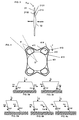
- FIGS. 6a to 6c schematically several geometries of different loops can be seen.
- the longitudinal axes of the legs are inclined on the same side relative to their respective radial.
- each loop P 1.1 , P 1.2 , P 2.1 , P 2.2
- the compression (C) acting on each loop (P 1.1 , P 1.2 , P 2.1 , P 2.2 ) when the lens is in place generates on each leg (21, 22) a loop (20), as in the art former, a centripetal component (Fc3, Fc4, Fc5) and a tangential component (Ft3, Ft4, Ft5).
- the tangential components Ft3, Ft4, Ft5 are oriented in the same direction which will cause the bending of the loop in the plane of the part (10) optical
- the longitudinal axes of the jambs (21, 22) of each handle are parallel.
- the axis passing through the optical center and parallel to the axes of the legs (21, 22), corresponding in other words to the axis of the jambs reported at the optical center O must be located outside the center O and arc angular sector corresponding to the portion (23) of contact.
- each span (23) is inscribed in a circle (C1 to C4) of center (O1 to O4) distinct from the optical center (O).
- the centers of the circles (C1 to C4), called eccentricity, in which the litters are written are located in the optical part.
- the centers (O1 to O4) of the circles (C1 to C4) are symmetrical in pairs, either with respect to the first diameter (D1), or with respect to the second diameter (D2), or with respect to center (O) optics. This characteristic makes it possible to obtain a better lateral stability of the lens, as well as a better self-centering.
- the centers (O1 to O4) of circles (C1 to C4) of eccentricity will move until they are confused or at least as close as possible from the center (O) optics.
- the circles (C1 to C4) are substantially merged with a circle (C0) defining the limits of the capsular bag.
- the configuration of the jambs (21, 22) of the loops than previously defined induces a difference in length of the jambs (21, 22). Therefore, during bending, the forces due to bending will be more important on the shorter leg (21).
- the eccentricity of the span (23) depends on the inclination of the handle. The greater the inclination (I) of the loops, the more the eccentricity, that is to say the distance between the optical center (O) and the center of the circle (C2) tangent to the span (23) is important, the more efforts will be reported on the longest leg (22).
- the surface of the leg section the most short (21) is more important than the surface of the most long (22).
- the section of the jambs is substantially rectangular shape with rounded corners.
- Figure 3 shows an alternative embodiment of the invention.
- the junction (213) between the first end of each jamb (21, 22) and the periphery of the optical portion (10) is of shape determined to prevent projection of the lens forward during its introduction into the capsular bag. By projection, it is necessary to understand displacement of the optical part according to the optical axis and inclination of the handles with respect to the plane of the optical part (10).
- the section cross-section or profile of the junction (213) is asymmetrical with respect to a plane perpendicular to the optical axis of the lens.
- the face (2131) of the junction (213) located in the extension of the front face the optical portion (10) is substantially perpendicular to the optical axis.
- the face (2132) of the junction (213) located in the extension of the face back of the optical portion (10) forms a determined angle with the face (2131) of the junction (213) located in the extension of the front face so the portion of the junction (213) adjacent to the optical portion (10) is more narrow than the portion of the junction (213) opposite to the optical portion (10).
- the projection of the part (10) backward optics is preferred over the projection towards forward.
- the rear projection can also be amplified using a loop plane inclined with respect to the optics.
- Figures 1 to 4 show a flexible monoblock lens.
- the principle of the invention which has just been described is transposable with rigid intraocular lenses. So, for a rigid intraocular lens, the loops will be reported on the periphery of the lens on locations provided for this purpose.
- each loop (P1.1, P1.2, P2.1, P2.2) comprises two arms (21, 22) or jambs whose first end is secured to the periphery of the optical part (10) and, for each handle (P1.1, P1.2, P2.1, P2.2), the axes longitudinal legs (21, 22) intersect at a point (S) not belonging to an angular sector whose center coincides with the optical center (O) of the optical part (10) and whose arc is constituted by a contact portion (23) joining the second ends of the jambs of the same handle.
- each loop (P1.1, P1.2, P2.1, P2.2) comprises two arms (21, 22) or legs, a first end is secured to the periphery of the optical part (10) and, for each handle (P1.1, P1.2, P2.1, P2.2), the longitudinal axes of the jambs (21, 22) are parallel, and the longitudinal axes of the legs (21, 22) do not are not included in an angular sector whose center is confused with the optical center (O) of the optical part (10) and whose arc is constituted by a contact portion (23) joining the second ends of the jambs of the same handle.
- the second ends of the jambs (21, 22) of each handle are connected by a portion (23) of contact or range inscribed or tangent to a circle (C1 to C4) no concentric with the optical center (O) of the optical part (10).
- the surface of the shorter leg section (21) is larger than the section of the jamb (22) the longest.
- the cross sections of the jambs (21, 22) are rectangular in shape with rounded corners.
- junction (213) between each jamb (21, 22) of each handle (P1.1, P1.2, P2.1, P2.2) has a profile longitudinal asymmetric.
- junction (213) between each jamb (21, 22) of each handle (P1.1, P1.2, P2.1, P2.2) is included in a plane forming a determined angle with the plane of the optical portion (10)
- the rear face (2131) of the junction is included in a plane perpendicular to the optical axis and the face front (2132) of the junction (213) is included in a plane forming an angle acute with the optical axis so that a rearward projection of the part optical is preferred.
- the intraocular lens is monobloc and is made of a flexible material.
- the intraocular lens is of the type rigid, the optical part being rigid and the handles (P1.1, P1.2, P2.1, P2.2) being flexible and reported or machined on the periphery of the optical part.
Landscapes
- Health & Medical Sciences (AREA)
- Ophthalmology & Optometry (AREA)
- Cardiology (AREA)
- Oral & Maxillofacial Surgery (AREA)
- Transplantation (AREA)
- Engineering & Computer Science (AREA)
- Biomedical Technology (AREA)
- Heart & Thoracic Surgery (AREA)
- Vascular Medicine (AREA)
- Life Sciences & Earth Sciences (AREA)
- Animal Behavior & Ethology (AREA)
- General Health & Medical Sciences (AREA)
- Public Health (AREA)
- Veterinary Medicine (AREA)
- Prostheses (AREA)
Claims (10)
- Intraokuläre Linse mitwobei die Henkel (P1.1, P1.2, P2.1, P2.2) jedes Paares symmetrisch zueinander mit Bezug auf einen zweiten Durchmesser (D2) sind, der im Wesentlichen senkrecht zu dem ersten Durchmesser (D1) ist,einem optischen Abschnitt (10) im Wesentlichen in Form einer Scheibe undeinem Halteabschnitt oder haptischen Abschnitt mit zwei Paaren von geschlossenen Henkeln (P1.1, P1.2, P2.1, P2.2), die symmetrisch mit Bezug auf einen ersten Durchmesser (D1) des optischen Abschnitts (10) angeordnet sind,
dadurch gekennzeichnet, dassjeder Henkel (P1.1, P1.2, P2.1, P2.2) zwei Arme oder Schenkel (21, 22) enthält, von denen jeder ein erstes Ende aufweist, das mit einem Rand des optischen Abschnitts (10) verbunden ist, und ein zweites Ende, das mit einem Kontaktabschnitt (23) verbunden ist, der die zwei Schenkel (21, 22) verbindet, undfür jeden Henkel (P1.1, P1.2, P2.1, P2.2) die Längsachsen der Schenkel (21, 22) sich in einem Punkt (S) schneiden, der nicht zu einem Winkelsektor gehört, dessen Mittelpunkt mit dem optischen Zentrum (O) des optischen Abschnitts (10) zusammenfällt und dessen Bogen durch den Kontaktabschnitt (23) gebildet wird, der die zweiten Enden der Schenkel desselben Henkels verbindet. - Intraokuläre Linse mitwobei die Henkel (P1.1, P1.2, P2.1, P2.2) jedes Paares symmetrisch zueinander mit Bezug auf einen zweiten Durchmesser (D2) sind, der im Wesentlichen senkrecht zu dem ersten Durchmesser (D1) ist,einem optischen Abschnitt (10) im Wesentlichen in Form einer Scheibe undeinem Halteabschnitt oder haptischen Abschnitt mit zwei Paaren von geschlossenen Henkeln (P1.1, P1.2, P2.1, P2.2), die symmetrisch mit Bezug auf einen ersten Durchmesser (D1) des optischen Abschnitts (10) angeordnet sind,
dadurch gekennzeichnet, dassjeder Henkel (P1.1, P1.2, P2.1, P2.2) zwei Arme oder Schenkel (21, 22) enthält, deren erstes Ende mit einem Rand des optischen Abschnitts (10) verbunden ist,für jeden Henkel (P1.1, P1.2, P2.1, P2.2) die Längsachsen der Schenkel (21, 22) zueinander parallel sind, unddie in das optische Zentrum versetzten Längsachsen der Schenkel (21, 22) nicht in einem Winkelsektor enthalten sind, dessen Mittelpunkt mit dem optischen Zentrum (O) des optischen Abschnitts (10) zusammenfällt und dessen Bogen durch einen Kontaktabschnitt (23) gebildet wird, der die zweiten Enden der Schenkel desselben Henkels verbindet. - Intraokuläre Linse nach Anspruch 1 oder 2, dadurch gekennzeichnet, dass jeder Kontaktabschnitt oder Träger (23) eingeschrieben in oder tangential zu einem Kreis (C1-C4) ist, der nicht mit dem optischen Zentrum (O) des optischen Abschnitts (10) konzentrisch ist.
- Intraokuläre Linse nach einem der Ansprüche 1 bis 3, dadurch gekennzeichnet, dass für jeden Henkel die Schnittfläche des kürzesten Schenkels (21) größer ist als die Schnittfläche des längsten Schenkels (22).
- Intraokuläre Linse nach Anspruch 4, dadurch gekennzeichnet, dass die Querschnitte der Schenkel (21, 22) rechteckförmig mit abgerundeten Kanten sind.
- Intraokuläre Linse nach einem der Ansprüche 1 bis 5, dadurch gekennzeichnet, dass die Verbindungsstelle (213) zwischen jedem Schenkel (21, 22) jedes Henkels (P1.1, P1.2, P2.1, P2.2) ein unsymmetrisches Längsprofil aufweist.
- Intraokuläre Linse nach einem der Ansprüche 1 bis 6, dadurch gekennzeichnet, dass die Verbindungsstelle (213) zwischen jedem Schenkel (21, 22) jedes Henkels (P1.1, P1.2, P2.1, P2.2) in einer Ebene enthalten ist, die einen vorbestimmten Winkel mit der Ebene des optischen Abschnitts (10) bildet.
- Intraokuläre Linse nach einem der Ansprüche 1 bis 7, dadurch gekennzeichnet, dassdie Rückfläche (2131) der Verbindungsstelle in einer Ebene senkrecht zu der optischen Achse enthalten ist unddie Vorderfläche (2132) der Verbindungsstelle (213) in einer Ebene enthalten ist, die einen spitzen Winkel mit der optischen Achse bildet, so dass ein Vorspringen des optischen Abschnitt nach hinten begünstigt ist.
- Intraokuläre Linse nach einem der Ansprüche 1 bis 8, dadurch gekennzeichnet, dass die intraokuläre Linse einstückig und aus einem biegsamen Material ausgebildet ist.
- Intraokuläre Linse nach einem der Ansprüche 1 bis 8, dadurch gekennzeichnet, dasswobei der optische Abschnitt starr ist unddie intraokuläre Linse von einem starren Typ ist,die Henkel (P1.1, P1.2, P2.1, P2.2) biegbar und an dem Rand des optischen Abschnitts angestückt oder angearbeitet sind.
Applications Claiming Priority (2)
| Application Number | Priority Date | Filing Date | Title |
|---|---|---|---|
| FR0012531A FR2814671B1 (fr) | 2000-10-02 | 2000-10-02 | Lentilles intraoculaires |
| FR0012531 | 2001-10-02 |
Publications (2)
| Publication Number | Publication Date |
|---|---|
| EP1222902A1 EP1222902A1 (de) | 2002-07-17 |
| EP1222902B1 true EP1222902B1 (de) | 2004-08-04 |
Family
ID=8854891
Family Applications (1)
| Application Number | Title | Priority Date | Filing Date |
|---|---|---|---|
| EP01402543A Expired - Lifetime EP1222902B1 (de) | 2000-10-02 | 2001-10-02 | Intraokuläre Linsen |
Country Status (6)
| Country | Link |
|---|---|
| US (1) | US6755860B2 (de) |
| EP (1) | EP1222902B1 (de) |
| AT (1) | ATE272370T1 (de) |
| DE (1) | DE60104642T2 (de) |
| ES (1) | ES2225442T3 (de) |
| FR (1) | FR2814671B1 (de) |
Families Citing this family (2)
| Publication number | Priority date | Publication date | Assignee | Title |
|---|---|---|---|---|
| US20070049952A1 (en) * | 2005-08-30 | 2007-03-01 | Weiss Steven J | Apparatus and method for mitral valve repair without cardiopulmonary bypass, including transmural techniques |
| FR2931356B1 (fr) * | 2008-05-21 | 2016-07-01 | Medicontur Orvostechnikai Korlatolt Felelossegu Tarsasag | Lentille intraoculaire |
Family Cites Families (4)
| Publication number | Priority date | Publication date | Assignee | Title |
|---|---|---|---|---|
| US4657546A (en) * | 1983-07-08 | 1987-04-14 | Shearing Steven P | Intraocular lens |
| FR2765797B1 (fr) * | 1997-07-08 | 1999-11-26 | Corneal Ind | Implant intraoculaire monobloc souple |
| FR2766699B1 (fr) | 1997-08-01 | 1999-11-26 | Corneal Ind | Implant intraoculaire monobloc souple |
| US6461384B1 (en) * | 1999-06-17 | 2002-10-08 | Bausch & Lomb Incorporated | Intraocular lenses |
-
2000
- 2000-10-02 FR FR0012531A patent/FR2814671B1/fr not_active Expired - Fee Related
-
2001
- 2001-10-02 ES ES01402543T patent/ES2225442T3/es not_active Expired - Lifetime
- 2001-10-02 AT AT01402543T patent/ATE272370T1/de active
- 2001-10-02 DE DE60104642T patent/DE60104642T2/de not_active Expired - Lifetime
- 2001-10-02 US US09/968,711 patent/US6755860B2/en not_active Expired - Fee Related
- 2001-10-02 EP EP01402543A patent/EP1222902B1/de not_active Expired - Lifetime
Also Published As
| Publication number | Publication date |
|---|---|
| ES2225442T3 (es) | 2005-03-16 |
| FR2814671B1 (fr) | 2003-04-04 |
| ATE272370T1 (de) | 2004-08-15 |
| DE60104642D1 (de) | 2004-09-09 |
| DE60104642T2 (de) | 2005-09-15 |
| FR2814671A1 (fr) | 2002-04-05 |
| US6755860B2 (en) | 2004-06-29 |
| EP1222902A1 (de) | 2002-07-17 |
| US20030065388A1 (en) | 2003-04-03 |
Similar Documents
| Publication | Publication Date | Title |
|---|---|---|
| EP0897294B1 (de) | Einteiliges verformbares intraokularlinsenimplantat | |
| EP1093775B1 (de) | Intraokulares Implantat | |
| CA2390888C (fr) | Implant intraoculaire precristallinien | |
| EP0935448B1 (de) | Intraokulares linsenimplantat mit einem weichen optischen teil und einem einstückigen kreisförmigen steifen bügel | |
| FR2776181A1 (fr) | Lentille intraoculaire monobloc souple | |
| WO2003063738A2 (fr) | Implant intracapsulaire accomodatif | |
| FR2991572A1 (fr) | Implant intraoculaire | |
| WO2009013421A1 (fr) | Implant intraoculaire souple a haptique circulaire | |
| EP1092402B1 (de) | Prismatische Hinterkammerlinse | |
| CA2340080C (fr) | Implant intra-oculaire de chambre anterieure | |
| EP1732472A2 (de) | Verbesserte intraokularlinse | |
| EP1222902B1 (de) | Intraokuläre Linsen | |
| BE1027321A1 (fr) | Implant phaque de chambre postérieure | |
| EP0566461B1 (de) | Intraokulares Implantat für Kapselsack | |
| FR2797177A1 (fr) | Implant intraoculaire precristallinien | |
| WO1995015733A1 (fr) | Implant intra-oculaire | |
| FR2858544A1 (fr) | Implant intraoculaire souple de faible epaisseur | |
| BE1029854B1 (fr) | Lentille intraoculaire phaque de chambre postérieure | |
| WO2009141354A1 (fr) | Lentille intraoculaire | |
| BE1026540B1 (fr) | Implant phaque de chambre postérieure | |
| FR2700466A1 (fr) | Implant de chambre postérieure pour aphaque atteint de forte myopie. | |
| WO2025078144A1 (fr) | Implant intracornéen | |
| EP1176928A1 (de) | Hinterkammerimplantat für schwerkurzsichtige aphaken | |
| FR3067591A1 (fr) | Implant intraoculaire pour le traitement de la cataracte chez l'homme et l'animal | |
| FR2899093A1 (fr) | Lentille intraoculaire refractive de chambre anterieure, notamment pour oeil phaque. |
Legal Events
| Date | Code | Title | Description |
|---|---|---|---|
| PUAI | Public reference made under article 153(3) epc to a published international application that has entered the european phase |
Free format text: ORIGINAL CODE: 0009012 |
|
| AK | Designated contracting states |
Kind code of ref document: A1 Designated state(s): AT BE CH CY DE DK ES FI FR GB GR IE IT LI LU MC NL PT SE TR |
|
| AX | Request for extension of the european patent |
Free format text: AL;LT;LV;MK;RO;SI |
|
| 17P | Request for examination filed |
Effective date: 20020701 |
|
| AKX | Designation fees paid |
Designated state(s): AT BE CH CY DE DK ES FI FR GB GR IE IT LI LU MC NL PT SE TR |
|
| 17Q | First examination report despatched |
Effective date: 20030807 |
|
| GRAP | Despatch of communication of intention to grant a patent |
Free format text: ORIGINAL CODE: EPIDOSNIGR1 |
|
| RIN1 | Information on inventor provided before grant (corrected) |
Inventor name: LIFFREDO, RENATO Inventor name: DELAGE, DENIS |
|
| GRAS | Grant fee paid |
Free format text: ORIGINAL CODE: EPIDOSNIGR3 |
|
| GRAA | (expected) grant |
Free format text: ORIGINAL CODE: 0009210 |
|
| AK | Designated contracting states |
Kind code of ref document: B1 Designated state(s): AT BE CH CY DE DK ES FI FR GB GR IE IT LI LU MC NL PT SE TR |
|
| PG25 | Lapsed in a contracting state [announced via postgrant information from national office to epo] |
Ref country code: CY Free format text: LAPSE BECAUSE OF FAILURE TO SUBMIT A TRANSLATION OF THE DESCRIPTION OR TO PAY THE FEE WITHIN THE PRESCRIBED TIME-LIMIT Effective date: 20040804 Ref country code: FI Free format text: LAPSE BECAUSE OF FAILURE TO SUBMIT A TRANSLATION OF THE DESCRIPTION OR TO PAY THE FEE WITHIN THE PRESCRIBED TIME-LIMIT Effective date: 20040804 |
|
| REG | Reference to a national code |
Ref country code: GB Ref legal event code: FG4D Free format text: NOT ENGLISH |
|
| REG | Reference to a national code |
Ref country code: CH Ref legal event code: EP |
|
| REG | Reference to a national code |
Ref country code: IE Ref legal event code: FG4D Free format text: FRENCH |
|
| REF | Corresponds to: |
Ref document number: 60104642 Country of ref document: DE Date of ref document: 20040909 Kind code of ref document: P |
|
| PG25 | Lapsed in a contracting state [announced via postgrant information from national office to epo] |
Ref country code: DK Free format text: LAPSE BECAUSE OF FAILURE TO SUBMIT A TRANSLATION OF THE DESCRIPTION OR TO PAY THE FEE WITHIN THE PRESCRIBED TIME-LIMIT Effective date: 20041104 Ref country code: SE Free format text: LAPSE BECAUSE OF FAILURE TO SUBMIT A TRANSLATION OF THE DESCRIPTION OR TO PAY THE FEE WITHIN THE PRESCRIBED TIME-LIMIT Effective date: 20041104 |
|
| REG | Reference to a national code |
Ref country code: GR Ref legal event code: EP Ref document number: 20040403750 Country of ref document: GR |
|
| GBT | Gb: translation of ep patent filed (gb section 77(6)(a)/1977) |
Effective date: 20041201 |
|
| REG | Reference to a national code |
Ref country code: ES Ref legal event code: FG2A Ref document number: 2225442 Country of ref document: ES Kind code of ref document: T3 |
|
| PLBE | No opposition filed within time limit |
Free format text: ORIGINAL CODE: 0009261 |
|
| STAA | Information on the status of an ep patent application or granted ep patent |
Free format text: STATUS: NO OPPOSITION FILED WITHIN TIME LIMIT |
|
| 26N | No opposition filed |
Effective date: 20050506 |
|
| REG | Reference to a national code |
Ref country code: CH Ref legal event code: NV Representative=s name: R. A. EGLI & CO. PATENTANWAELTE |
|
| PGFP | Annual fee paid to national office [announced via postgrant information from national office to epo] |
Ref country code: TR Payment date: 20061106 Year of fee payment: 6 |
|
| PG25 | Lapsed in a contracting state [announced via postgrant information from national office to epo] |
Ref country code: PT Free format text: LAPSE BECAUSE OF NON-PAYMENT OF DUE FEES Effective date: 20050104 |
|
| PG25 | Lapsed in a contracting state [announced via postgrant information from national office to epo] |
Ref country code: TR Free format text: LAPSE BECAUSE OF FAILURE TO SUBMIT A TRANSLATION OF THE DESCRIPTION OR TO PAY THE FEE WITHIN THE PRESCRIBED TIME-LIMIT Effective date: 20040804 |
|
| PGFP | Annual fee paid to national office [announced via postgrant information from national office to epo] |
Ref country code: LU Payment date: 20140220 Year of fee payment: 13 |
|
| PGFP | Annual fee paid to national office [announced via postgrant information from national office to epo] |
Ref country code: IE Payment date: 20140130 Year of fee payment: 13 Ref country code: MC Payment date: 20140221 Year of fee payment: 13 |
|
| PGFP | Annual fee paid to national office [announced via postgrant information from national office to epo] |
Ref country code: GR Payment date: 20140328 Year of fee payment: 13 Ref country code: BE Payment date: 20140220 Year of fee payment: 13 Ref country code: AT Payment date: 20140203 Year of fee payment: 13 |
|
| PG25 | Lapsed in a contracting state [announced via postgrant information from national office to epo] |
Ref country code: LU Free format text: LAPSE BECAUSE OF NON-PAYMENT OF DUE FEES Effective date: 20141002 Ref country code: MC Free format text: LAPSE BECAUSE OF NON-PAYMENT OF DUE FEES Effective date: 20141031 |
|
| REG | Reference to a national code |
Ref country code: AT Ref legal event code: MM01 Ref document number: 272370 Country of ref document: AT Kind code of ref document: T Effective date: 20141002 |
|
| REG | Reference to a national code |
Ref country code: GR Ref legal event code: ML Ref document number: 20040403750 Country of ref document: GR Effective date: 20150505 |
|
| PG25 | Lapsed in a contracting state [announced via postgrant information from national office to epo] |
Ref country code: BE Free format text: LAPSE BECAUSE OF NON-PAYMENT OF DUE FEES Effective date: 20141031 |
|
| REG | Reference to a national code |
Ref country code: IE Ref legal event code: MM4A |
|
| PG25 | Lapsed in a contracting state [announced via postgrant information from national office to epo] |
Ref country code: AT Free format text: LAPSE BECAUSE OF NON-PAYMENT OF DUE FEES Effective date: 20141002 Ref country code: GR Free format text: LAPSE BECAUSE OF NON-PAYMENT OF DUE FEES Effective date: 20150505 |
|
| REG | Reference to a national code |
Ref country code: FR Ref legal event code: PLFP Year of fee payment: 15 |
|
| PG25 | Lapsed in a contracting state [announced via postgrant information from national office to epo] |
Ref country code: IE Free format text: LAPSE BECAUSE OF NON-PAYMENT OF DUE FEES Effective date: 20141002 |
|
| REG | Reference to a national code |
Ref country code: FR Ref legal event code: PLFP Year of fee payment: 16 |
|
| REG | Reference to a national code |
Ref country code: FR Ref legal event code: PLFP Year of fee payment: 17 |
|
| PGFP | Annual fee paid to national office [announced via postgrant information from national office to epo] |
Ref country code: FR Payment date: 20171026 Year of fee payment: 17 Ref country code: DE Payment date: 20171121 Year of fee payment: 17 Ref country code: NL Payment date: 20171030 Year of fee payment: 17 |
|
| PGFP | Annual fee paid to national office [announced via postgrant information from national office to epo] |
Ref country code: GB Payment date: 20171123 Year of fee payment: 17 Ref country code: ES Payment date: 20171121 Year of fee payment: 17 Ref country code: IT Payment date: 20171024 Year of fee payment: 17 Ref country code: CH Payment date: 20171123 Year of fee payment: 17 |
|
| REG | Reference to a national code |
Ref country code: DE Ref legal event code: R119 Ref document number: 60104642 Country of ref document: DE |
|
| REG | Reference to a national code |
Ref country code: CH Ref legal event code: PL |
|
| REG | Reference to a national code |
Ref country code: NL Ref legal event code: MM Effective date: 20181101 |
|
| GBPC | Gb: european patent ceased through non-payment of renewal fee |
Effective date: 20181002 |
|
| PG25 | Lapsed in a contracting state [announced via postgrant information from national office to epo] |
Ref country code: NL Free format text: LAPSE BECAUSE OF NON-PAYMENT OF DUE FEES Effective date: 20181101 Ref country code: DE Free format text: LAPSE BECAUSE OF NON-PAYMENT OF DUE FEES Effective date: 20190501 |
|
| PG25 | Lapsed in a contracting state [announced via postgrant information from national office to epo] |
Ref country code: CH Free format text: LAPSE BECAUSE OF NON-PAYMENT OF DUE FEES Effective date: 20181031 Ref country code: FR Free format text: LAPSE BECAUSE OF NON-PAYMENT OF DUE FEES Effective date: 20181031 Ref country code: LI Free format text: LAPSE BECAUSE OF NON-PAYMENT OF DUE FEES Effective date: 20181031 |
|
| PG25 | Lapsed in a contracting state [announced via postgrant information from national office to epo] |
Ref country code: GB Free format text: LAPSE BECAUSE OF NON-PAYMENT OF DUE FEES Effective date: 20181002 Ref country code: IT Free format text: LAPSE BECAUSE OF NON-PAYMENT OF DUE FEES Effective date: 20181002 |
|
| REG | Reference to a national code |
Ref country code: ES Ref legal event code: FD2A Effective date: 20191129 |
|
| PG25 | Lapsed in a contracting state [announced via postgrant information from national office to epo] |
Ref country code: ES Free format text: LAPSE BECAUSE OF NON-PAYMENT OF DUE FEES Effective date: 20181003 |