EP1222845B1 - Method for separating seedling blocks, device for implementing said method and planting machine comprising such a device - Google Patents
Method for separating seedling blocks, device for implementing said method and planting machine comprising such a device Download PDFInfo
- Publication number
- EP1222845B1 EP1222845B1 EP20010400092 EP01400092A EP1222845B1 EP 1222845 B1 EP1222845 B1 EP 1222845B1 EP 20010400092 EP20010400092 EP 20010400092 EP 01400092 A EP01400092 A EP 01400092A EP 1222845 B1 EP1222845 B1 EP 1222845B1
- Authority
- EP
- European Patent Office
- Prior art keywords
- soil block
- soil
- movement
- axis
- stirrup
- Prior art date
- Legal status (The legal status is an assumption and is not a legal conclusion. Google has not performed a legal analysis and makes no representation as to the accuracy of the status listed.)
- Expired - Lifetime
Links
- 238000000034 method Methods 0.000 title claims description 15
- 239000002689 soil Substances 0.000 claims description 37
- 238000005192 partition Methods 0.000 claims description 10
- 230000000717 retained effect Effects 0.000 claims description 10
- 238000000926 separation method Methods 0.000 claims description 8
- 238000006073 displacement reaction Methods 0.000 claims description 5
- 241000196324 Embryophyta Species 0.000 description 11
- 230000000694 effects Effects 0.000 description 11
- 240000007087 Apium graveolens Species 0.000 description 3
- 230000010355 oscillation Effects 0.000 description 3
- 230000001360 synchronised effect Effects 0.000 description 3
- 240000008415 Lactuca sativa Species 0.000 description 2
- 239000000470 constituent Substances 0.000 description 2
- 239000002184 metal Substances 0.000 description 2
- 238000004382 potting Methods 0.000 description 2
- 235000012045 salad Nutrition 0.000 description 2
- 235000015849 Apium graveolens Dulce Group Nutrition 0.000 description 1
- 235000010591 Appio Nutrition 0.000 description 1
- 244000024251 Aralia cordata Species 0.000 description 1
- 241000446313 Lamella Species 0.000 description 1
- 238000010586 diagram Methods 0.000 description 1
- 238000013507 mapping Methods 0.000 description 1
- 210000000056 organ Anatomy 0.000 description 1
- 230000002093 peripheral effect Effects 0.000 description 1
- 238000007493 shaping process Methods 0.000 description 1
- 239000000758 substrate Substances 0.000 description 1
- 238000011144 upstream manufacturing Methods 0.000 description 1
- 235000013311 vegetables Nutrition 0.000 description 1
Images


Classifications
-
- A—HUMAN NECESSITIES
- A01—AGRICULTURE; FORESTRY; ANIMAL HUSBANDRY; HUNTING; TRAPPING; FISHING
- A01C—PLANTING; SOWING; FERTILISING
- A01C11/00—Transplanting machines
- A01C11/02—Transplanting machines for seedlings
- A01C11/025—Transplanting machines using seedling trays; Devices for removing the seedlings from the trays
Definitions
- the present invention relates, in the field of vegetable crops, a method according to the preamble of claim 1, for separating cubic clods which are grouped in the form of linear blocks consisting of several clumps, five or ten generally.
- the invention also relates to the device according to the preamble of claim 3 for implementing the method as well as the planting machine which comprises such a device.
- These machines for planting cubic clods comprise at least one corridor in which an operator arranges the clumps or rather the groups of clumps that he takes in a tray that has at least a hundred plants.
- Such a machine is described for example in the document EP-A-0 550 821 .
- the clumps are in fact arranged on an endless carpet that pushes said clods against a retaining stop.
- the clods are then taken at the end of the corridor, one by one, to be earthed by a suitable system, usually a battery of radiating pliers whose peripheral speed at the time of removal from the ground is zero in relation to this last, for a certain range of planting steps.
- the clumps consist of a suitable substrate of the genus potting soil, compacted and delimited by lateral faces. They are in the form of small cubes whose dimensions are of the order of 3 to 5 cm.
- the plants develop in the clumps from a seed that has been placed in the heart of the said root ball and, depending on the nature of the plants and also the conditions in which they have developed, there may be between the clumps and especially between the clumps of the same group, adhesions and even some cohesion due to the presence of rootlets that cross the adjoining walls and develop in the adjacent clump or clumps.
- the present invention proposes means which make it possible to reduce the risks of incidents and especially of failures resulting from the causes mentioned above, which means consist of a preliminary, automatic operation which has the effect of physically separating the clumps by first removing all or part of the adhesions and especially by breaking the connections of the kind rootlets.
- the invention provides a method as characterized in claim 1 and a device comprising the features of claim 3.
- the method according to the invention consists in effect - to grasp and hold the clods, on both sides of the adjacent walls where it is intended to perform the separation, then - to print a relative torsion movement between said adjacent clumps, of sufficient magnitude to effect a fracture and remove all or part of the adhesions and the like which are at the level of said adjacent walls, and then - to spread said clumps relative to each other in order to complete the separation.
- the method consists in printing the oscillating torsion movement about a fixed axis which is perpendicular to the surface of the corridor on which the clumps rest, one of the clumps being held fixed on said surface and in the corridor by pinching on its flanks, the other root being also maintained on its flanks by pinching by the appropriate device capable of printing said oscillating torsion movement.
- the invention also relates to the device for implementing the separation method, which device comprises, between the lane supply of the clumps and groups of clumps and the grounding system, means for taking care of the first clump. retained by means of a retractable abutment at the downstream end of said passage, which support means are provided with a movement capacity which makes it possible to print on said first root ball an oscillating torsion movement with respect to the second mound which is retained at the end of said corridor.
- the support means consist of a kind of stirrup, which stirrup is mounted on an axis and is movable on this axis, operated by a suitable reciprocating member of the cylinder type or another to realize the twisting movement of the first ball with respect to the second ball.
- the torsion movement of the first root ball, around the axis of articulation of the stirrup is an oscillating movement which takes place at an angle which is of the order of about 15 °.
- the support means are also provided with another movement capacity, additional, which consists in moving the first root ball between the end of the supply corridor and an intermediate transfer belt that feeds the grounding system, which displacement also allows, for certain types of plants, to perform a separation operation and / or disentangling limbs or leaves intertwined.
- the support shaft of the stirrup is mounted on a movable frame which moves the gripper system between the position of taking care of the first root ball, at the end of said feed passage. , and the position of removal and release of said first clump on the intermediate belt, which movement of the first clump takes place above a platform made of sheet metal, integral with the general chassis of the machine, which plate -form extends between the end of the supply conveyor belt and the entrance of said intermediate belt.
- the support frame of the gripper system is in the form of a carriage, which carriage is movable on slides along the axis of advancement of the clumps, under the effect of a suitable actuating member of the jack type, for example, which carriage slides the clod taken in the gripper system, on the platform to the entrance of the intermediate belt, which intermediate belt supports said clod as soon as it is released from the clamp system.
- the support frame of the gripper system is pivotally mounted about a transverse axis, perpendicular to the axis of advancement of the clods, which frame is movable under the effect of an appropriate actuating member of the like jack and prints to the gripper system and the clod taken between the clamps, a movement in an arc of a circle between the position of takeover of the first clump at the end of the feed chute and the discharge position of said first clod on the entrance of the intermediate belt, which motte sweeps the platform which is also in the form of a circular arc.
- the intermediate belt is an endless belt comprising arrangements in the form of compartments that move the clumps and present them to the grounding system in a synchronized manner.
- This compartmentalized intermediate belt makes it possible, for certain types of plants, to complete the disentangling of the leaves.
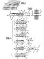
- the figure 1 shows the cubic clods 1, made of potting soil, in which the plants of salads, celery or others grow. These clumps are shaped and arranged on trays, not shown, separated each other while shaping, however, as shown figure 1 groups of clumps in the form of linear blocks, which blocks comprise for example five or ten clumps juxtaposed.
- the main organs of this planting machine are schematically represented, figure 2 , seen from above.
- the clods or groups of clumps are arranged in a feed chute 2 which comprises an endless belt 3 and side walls 4 and 5.
- a retractable stop 6 which stops the first clod of the group, and, beyond this stop, a carpet 7 which takes the clumps.
- These clods are in fact supported by a system of clamps 8 which are located at the end of the passage 2, between the ends of the walls 4 and 5 and the stop 6.
- the gripper system transfers the first clump on the carpet 7 , which carpet takes the clods to a grounding system 9 consisting of radiating clamps 10 which deposit each clump on the ground, at zero speed relative to the ground.
- the clods 1 are deposited one by one in a groove 12 which is dug by a share 13, as and when the machine.
- the clumps 1 are deposited in the groove 12 by the clamps 10, which clamps support each clump which is transferred by means of the intermediate belt 7.
- the clumps can, for example, be taken care of directly by the radiating pliers 10, at the exit of the corridor 2.
- rootlets are sometimes so interwoven, from one mound to another, that the separation by means of the clamps is random.
- FIG 3 illustrates, by a series of operations marked from a to f , the different phases of the process which makes it possible to effectively separate the clumps with respect to each other and in particular as illustrated figure 3 a , the first clod which is located at the downstream end of the passage 2, retained by the stop 6 and located in the gripper system 8, with respect to the second clod which is retained in said passage 2 by means of the ends of the walls lateral 4 and 5.
- the gripper system 8 comprises forceps 15 in the form of a square plate, for example, which enclose the free lateral faces of the first root ball.
- the second mound is pinched between the end of the side wall 5 which is for example fixed, secured to the general frame 16 of the machine, and the end of the side wall 4 which is movable, under the effect of a jack 17.
- the figure 3 b shows that the first clump is retained and supported by means of the clamps 15 which are actuated by jacks 18.
- the second clod and the clods that follow are always retained at the end of the passage 2, clamped between the walls 4 and 5 and in particular by the end of the wall 4, by means of the jack 17 which deforms the end of said wall.
- This wall 4 is in the form of an elastic lamella which is deformable over the length of two clumps, for example.
- the gripper system 8 is detailed below in connection with the figure 5 and comprises two cylinders 18 which make it possible to tighten the first root ball.
- the figure 3 c shows the movement of the first clod, printed by the gripper system 8, which movement makes it possible to break all or part of the adhesions between the first and second clod, which second cleat is retained at the end of the passage 2, pinched between the walls 4 and 5.
- This movement consists of a limited rotation of the first root ball around an axis which corresponds to the axis of the plantation made in said first root ball, that is to say an axis perpendicular to the surface of the platform 11 which constitutes the bottom of the corridor 2.
- This rotation is performed in a fast movement back and forth, on an angle which is for example of the order of 15 °.
- the jacks 17 and 18 are put back into operation for, on the one hand, thanks to the jack 17, pinch the second root ball and retain the clumps from the second in the corridor. brought 2 and, secondly, thanks to the jacks 18, pinch the first clod which is located in the clamps 15; then 1 stop 6 is retracted.
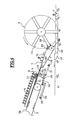
- the figure 4 shows, in the form of a schematic elevation, the various constituent elements of the machine.
- the gripper system 8 also appears in relation to the first block, which first block is retained by means of the stop 6, which stop is actuated by means of a jack 20 which is secured to the frame 16 via the flat plate. 11.
- the stop 6 is in the form of a finger which, in the active position, protrudes above the platform 11. This finger forming the stop 6, moves along an axis perpendicular to the platform. form 11.
- the intermediate belt 7 is guided between several pulleys and in particular between two pulleys 22 and 23 which make it possible to maintain the strand 71 of the belt in the extension of the platform 11, then between the pulley 23 and a driving pulley 24 which make it possible to forming a strand tangent to the circumference generated by the end of the radiating clamps 10 so as to present the root ball, said clamps, in a suitable position for its grounding.
- the gripper system 8 is shown figure 4 in the support position of the first root ball. It is movable between this support position at the end of the corridor 2 and an unloading position, at the entrance of the intermediate belt 7.
- This clamp system is mounted on a frame 30 which is guided on slides 31 secured chassis 16; this frame 30 is movable under the effect of a jack 32 fixed to the frame 16.
- the slides 31 extend under the platform 11, from the end of the corridor 2 to the inlet of the intermediate belt 7. They are parallel to the upper surface 33 of the belt 3, to the platform 11 and at the strand 71 of the carpet 7.
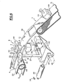
- the gripper system consists in fact of a stirrup-shaped support 35 which extends above the frame 30, mounted on an axis 36 perpendicular to the slideways 31.
- This support stirrup comprises, at the upper end of its branches 37, the cylinders 18 which actuate the clamps 15, which clamps are in contact with the side faces of the first block 1.
- the axis 36 is in the median vertical plane of the corridor 2 and it passes through the heart of the root ball which is supported by the gripper system.
- the stirrup is movable about the axis 36 under the effect of a jack 40 mounted on the frame 30, which cylinder imparts a pivoting movement back and forth of the stirrup 35 about the axis 36 with a magnitude angular of the order of 15 °.
- This oscillation movement reported at the level of the clamps 15, causes a torsion and a fracture between the first and the second clod, which makes it possible to separate said first clod taken between the clamps 15, the following clod retained at the end. from corridor 2.
- This operation separation of the first and second clods is performed after retraction of the abutment 6.
- the first root ball is driven towards the intermediate belt 7 by the displacement of the frame 30 under the effect of the jack 32.
- the intermediate belt 7 has, as previously mentioned, partitions 19 which protrude so as to form a wedging compartment to frame the ball and move in a movement which is synchronized with the movement of the radiating clamps 10.
- an opening 39 faces the upstream end of the intermediate belt 7 to allow the passage of the partitions 19 which enclose the clod brought by the gripper system 8.
- the clumps are brought by the belt 3 and, at the end of this belt 3, downstream of the roller 43, the clods take place on the platform 11 which extends the upper strand 33 of said belt 3.
- the frame 30 is movable, articulated on an axis 45 which is horizontal, and transverse and perpendicular to the direction of advancement of the clods.
- this axis 45 is perpendicular and secant with the axis 36 which allows the pivoting of the stirrup 37; it is located under the stirrup 37.
- the platform 11 is also shaped in an arc and extends to the carpet intermediate 7.
- the upper strand 71 of the intermediate belt 7 extends in the extension of the downstream end of the platform 11.
- the conveyor belt 3 which brings the clods to the gripper system may have a smaller inclination than the one represented figure 4 .
- the upper run 71 of the belt 7 may have a greater inclination.
- the figure 7 shows in more detail in the form of elevation, the platform 11 which extends between the end drum 43 of the conveyor belt 3 and the end drum 22 of the belt 7.
- This platform 11 firstly comprises a rectilinear part 110 which extends between the belt 3 and the position of the first root ball when it is supported, then a sector 111 in the form of an arc of a circle centered on the axis 45 around which the frame 30 and the gripper system 8 swing.
- the gripper system 8 is shown, on the one hand, in the load-bearing position of the first root ball at the end of the feed passage 2 and, on the other hand, in the unloading position of the first root ball. the carpet entrance 7.
- the angle of tilting from one position to the other around the axis 45 is of the order of 30 ° to 60 °.
- the stop 6 extends projecting above the platform 11 and in particular the sector 111.
- This stop 6 is operated by the jack 20 which is located under the platform 11, which cylinder is secured to said platform by a tab 50, which platform is itself secured to the frame 16.
- the pivoting and tilting movement of the gripper system 8 about the axis 36 is effected as in the previous embodiment, by means of a jack 40 which is associated with the frame 30.
- This gripper system 8 and in particular the stirrup 37 is for example mounted on an axis 51 integral with the frame 30 by means of bearings 52 simply schematized figure 7 .
- the root ball is deposited between two partitions 19 and we notice, figure 7 , that the root ball is deposited behind a partition 19 which extends perpendicularly to the strand 71 of the carpet 7 while the following partition is still substantially in a position perpendicular to the first partition, under the platform 11.
- the planting machine preferably comprises an automaton for controlling and coordinating the different movements of the actuating jacks, that is to say: the jack 17 at the end of the passage 4, the jacks 18 for actuating the clamps 15, the jack 20 of the abutment 6, the actuator 32 for actuating the frame 30 and the jack 40 for pivoting the gripper system 8.
- These various cylinders are preferably pneumatic actuators.
- the movements are coordinated by taking as a reference the movement of the grounding system and / or that of the intermediate belt 7, the speed of each is a function of the speed of advance of the machine on the ground.
Description
La présente invention concerne, dans le domaine des cultures maraîchères, un procédé selon le préambule de la revendication 1, pour séparer des mottes cubiques qui sont regroupées sous forme de blocs linéaires constitués de plusieurs mottes, cinq ou dix généralement.The present invention relates, in the field of vegetable crops, a method according to the preamble of
L'invention concerne également le dispositif selon le préambule de la revendication 3 pour la mise en oeuvre du procédé ainsi que la machine de plantation qui comprend un tel dispositif.The invention also relates to the device according to the preamble of
Ces machines de plantation de mottes cubiques comprennent au moins un couloir dans lequel un opérateur dispose les mottes ou plutôt les groupes de mottes qu'il prélève dans un plateau qui comporte au moins une centaine de plants. Une telle machine est décrit par exemple dans le document
Dans ce couloir, les mottes sont en fait disposées sur un tapis sans fin qui pousse lesdites mottes contre une butée de retenue. Les mottes sont ensuite prises à l'extrémité du couloir, une par une, pour être mises en terre par un système approprié, généralement une batterie de pinces rayonnantes dont la vitesse périphérique au moment de la dépose sur le sol est nulle par rapport à ce dernier, pour une certaine plage de pas de plantation.In this corridor, the clumps are in fact arranged on an endless carpet that pushes said clods against a retaining stop. The clods are then taken at the end of the corridor, one by one, to be earthed by a suitable system, usually a battery of radiating pliers whose peripheral speed at the time of removal from the ground is zero in relation to this last, for a certain range of planting steps.
Les mottes sont constituées d'un substrat approprié du genre terreau, compacté et délimité par des faces latérales. Elles se présentent sous la forme de petits cubes dont les dimensions sont de l'ordre de 3 à 5 cm.The clumps consist of a suitable substrate of the genus potting soil, compacted and delimited by lateral faces. They are in the form of small cubes whose dimensions are of the order of 3 to 5 cm.
Les plants se développent dans les mottes à partir d'une graine qui a été disposée au coeur de ladite motte et, selon la nature des plants et aussi les conditions dans lesquelles ils se sont développés, il peut y avoir entre les mottes et surtout entre les mottes d'un même groupe, des adhérences et même une certaine cohésion due à la présence de radicelles qui traversent les parois jointives et se développent dans la ou les mottes adjacentes.The plants develop in the clumps from a seed that has been placed in the heart of the said root ball and, depending on the nature of the plants and also the conditions in which they have developed, there may be between the clumps and especially between the clumps of the same group, adhesions and even some cohesion due to the presence of rootlets that cross the adjoining walls and develop in the adjacent clump or clumps.
Ces adhérences et cohésions sont une source d'incidents sur les planteuses et provoquent des ratés de séparation.These adhesions and cohesions are a source of incidents on the planters and cause misfires.
D'autres causes d'incidents proviennent de l'état des mottes au moment de la plantation et en particulier de leur dureté car elles peuvent être sèches ou humides, voire très humides.Other causes of incidents come from the condition of the clumps at the time of planting and in particular their hardness because they can be dry or wet, or very wet.
La présente invention propose des moyens qui permettent de diminuer les risques d'incidents et surtout de ratés provenant des causes rappelées ci-dessus, lesquels moyens consistent en une opération préalable, automatique, qui a pour effet de séparer physiquement les mottes en supprimant d'abord tout ou partie des adhérences et surtout en brisant les liaisons du genre radicelles.The present invention proposes means which make it possible to reduce the risks of incidents and especially of failures resulting from the causes mentioned above, which means consist of a preliminary, automatic operation which has the effect of physically separating the clumps by first removing all or part of the adhesions and especially by breaking the connections of the kind rootlets.
Pour résoudre le problème, l'invention propose un procédé comme il est caractérisé dans la revendications 1 ainsi qu'un dispositif comportant les caractéristiques de la revendication 3.To solve the problem, the invention provides a method as characterized in
Le procédé selon l'invention consiste en effet - à saisir et maintenir les mottes, de part et d'autre des parois adjacentes où il est prévu d'effectuer la séparation, puis - à imprimer un mouvement de torsion relatif entre lesdites mottes adjacentes, d'une amplitude suffisante pour réaliser une fracture et supprimer tout ou partie des adhérences et autres qui se situent au niveau desdites parois adjacentes, et ensuite - à écarter lesdites mottes l'une par rapport à l'autre afin de parachever la séparation.The method according to the invention consists in effect - to grasp and hold the clods, on both sides of the adjacent walls where it is intended to perform the separation, then - to print a relative torsion movement between said adjacent clumps, of sufficient magnitude to effect a fracture and remove all or part of the adhesions and the like which are at the level of said adjacent walls, and then - to spread said clumps relative to each other in order to complete the separation.
Toujours selon l'invention, le procédé consiste à imprimer le mouvement de torsion oscillant autour d'un axe fixe qui est perpendiculaire à la surface du couloir sur laquelle reposent les mottes, l'une des mottes étant maintenue fixe sur ladite surface et dans le couloir par pincement sur ses flancs, l'autre motte étant également maintenue sur ses flancs par pincement par le dispositif approprié susceptible d'imprimer ledit mouvement de torsion oscillant.Still according to the invention, the method consists in printing the oscillating torsion movement about a fixed axis which is perpendicular to the surface of the corridor on which the clumps rest, one of the clumps being held fixed on said surface and in the corridor by pinching on its flanks, the other root being also maintained on its flanks by pinching by the appropriate device capable of printing said oscillating torsion movement.
L'invention concerne également le dispositif de mise en oeuvre du procédé de séparation, lequel dispositif comprend, entre le couloir d'amenée des mottes et groupes de mottes et le système de mise en terre, des moyens de prise en charge de la première motte retenue par l'intermédiaire d'une butée escamotable à l'extrémité aval dudit couloir, lesquels moyens de prise en charge sont dotés d'une capacité de mouvement qui permet d'imprimer à ladite première motte un mouvement de torsion oscillant par rapport à la deuxième motte qui est retenue à l'extrémité dudit couloir.The invention also relates to the device for implementing the separation method, which device comprises, between the lane supply of the clumps and groups of clumps and the grounding system, means for taking care of the first clump. retained by means of a retractable abutment at the downstream end of said passage, which support means are provided with a movement capacity which makes it possible to print on said first root ball an oscillating torsion movement with respect to the second mound which is retained at the end of said corridor.
Selon une autre disposition de l'invention, les moyens de prise en charge consistent en une sorte d'étrier, lequel étrier est monté sur un axe et il est mobile sur cet axe, manoeuvré par un organe approprié à mouvement alternatif du genre vérin ou autre pour réaliser le mouvement de torsion de la première motte par rapport à la deuxième motte.According to another embodiment of the invention, the support means consist of a kind of stirrup, which stirrup is mounted on an axis and is movable on this axis, operated by a suitable reciprocating member of the cylinder type or another to realize the twisting movement of the first ball with respect to the second ball.
Selon l'invention, le mouvement de torsion de la première motte, autour de l'axe d'articulation de l'étrier, est un mouvement oscillant qui s'effectue sur un angle qui est de l'ordre de 15° environ.According to the invention, the torsion movement of the first root ball, around the axis of articulation of the stirrup, is an oscillating movement which takes place at an angle which is of the order of about 15 °.
Toujours selon l'invention, les moyens de prise en charge sont également dotés d'une autre capacité de mouvement, supplémentaire, qui consiste à déplacer la première motte entre l'extrémité du couloir d'amenée et un tapis intermédiaire de transfert qui alimente le système de mise en terre, lequel déplacement permet aussi, pour certains types de plants, d'effectuer une opération de séparation et/ou démêlage des limbes ou feuilles entremêlés.Still according to the invention, the support means are also provided with another movement capacity, additional, which consists in moving the first root ball between the end of the supply corridor and an intermediate transfer belt that feeds the grounding system, which displacement also allows, for certain types of plants, to perform a separation operation and / or disentangling limbs or leaves intertwined.
Selon une autre disposition de l'invention, l'axe support de l'étrier est monté sur un bâti mobile qui déplace le système de pinces entre la position de prise en charge de la première motte, à l'extrémité dudit couloir d'amenée, et la position de dépose et de libération de ladite première motte sur le tapis intermédiaire, lequel déplacement de la première motte s'effectue au-dessus d'une plate-forme réalisée en tôle, solidaire du châssis général de la machine, laquelle plate-forme s'étend entre l'extrémité du tapis convoyeur d'amenée et l'entrée dudit tapis intermédiaire.According to another embodiment of the invention, the support shaft of the stirrup is mounted on a movable frame which moves the gripper system between the position of taking care of the first root ball, at the end of said feed passage. , and the position of removal and release of said first clump on the intermediate belt, which movement of the first clump takes place above a platform made of sheet metal, integral with the general chassis of the machine, which plate -form extends between the end of the supply conveyor belt and the entrance of said intermediate belt.
Selon une première possibilité de l'invention, le bâti support du système de pinces se présente sous la forme d'un chariot, lequel chariot est mobile sur des glissières selon l'axe d'avancement des mottes, sous l'effet d'un organe de manoeuvre approprié du genre vérin par exemple, lequel chariot fait glisser la motte prise dans le système de pinces, sur la plate-forme jusqu'à l'entrée du tapis intermédiaire, lequel tapis intermédiaire prend en charge ladite motte dès qu'elle est libérée du système de pinces.According to a first possibility of the invention, the support frame of the gripper system is in the form of a carriage, which carriage is movable on slides along the axis of advancement of the clumps, under the effect of a suitable actuating member of the jack type, for example, which carriage slides the clod taken in the gripper system, on the platform to the entrance of the intermediate belt, which intermediate belt supports said clod as soon as it is released from the clamp system.
Selon une variante de réalisation, le bâti support du système de pinces est monté basculant autour d'un axe transversal, perpendiculaire à l'axe d'avancement des mottes, lequel bâti est mobile sous l'effet d'un organe de manoeuvre approprié du genre vérin et imprime au système de pinces et à la motte prise entre les pinces, un mouvement selon un arc de cercle entre la position de prise en charge de la première motte à l'extrémité du couloir d'amenée et la position de décharge de ladite première motte sur l'entrée du tapis intermédiaire, laquelle motte balaye la plate-forme qui se présente elle aussi en forme d'arc de cercle.According to an alternative embodiment, the support frame of the gripper system is pivotally mounted about a transverse axis, perpendicular to the axis of advancement of the clods, which frame is movable under the effect of an appropriate actuating member of the like jack and prints to the gripper system and the clod taken between the clamps, a movement in an arc of a circle between the position of takeover of the first clump at the end of the feed chute and the discharge position of said first clod on the entrance of the intermediate belt, which motte sweeps the platform which is also in the form of a circular arc.
Selon une autre disposition de l'invention, le tapis intermédiaire est un tapis sans fin comportant des aménagements sous forme de compartiments qui permettent de déplacer les mottes et de les présenter au système de mise en terre de façon synchronisée. Ce tapis intermédiaire compartimenté permet, pour certains types de plants, de parachever le démêlage des feuilles.According to another embodiment of the invention, the intermediate belt is an endless belt comprising arrangements in the form of compartments that move the clumps and present them to the grounding system in a synchronized manner. This compartmentalized intermediate belt makes it possible, for certain types of plants, to complete the disentangling of the leaves.
L'invention concerne également la machine équipée d'un tel dispositif de mise en oeuvre du procédé, laquelle machine comporte un automate qui coordonne, à partir du mouvement du système de mise en terre et/ou du mouvement du tapis intermédiaire dont la vitesse de chacun est fonction de la vitesse de déplacement de la machine, l'ensemble des vérins de manoeuvre c'est-à-dire :
- le vérin de serrage et de retenue des mottes à partir de la deuxième, à l'extrémité du couloir d'amenée ;
- le vérin de manoeuvre de la butée d'arrêt de la première motte en bout du couloir d'amenée ;
- les vérins montés sur l'étrier formant pinces ;
- le vérin de manoeuvre de l'étrier pour réaliser le mouvement de torsion de la première motte ;
- le vérin de manoeuvre du chariot qui porte l'étrier.
- the cylinder for clamping and retaining clods from the second, at the end of the supply corridor;
- the actuating cylinder of the abutment stop of the first root ball at the end of the supply corridor;
- the cylinders mounted on the stirrup forming tongs;
- the actuator cylinder of the stirrup for carrying out the twisting movement of the first root ball;
- the actuating cylinder of the carriage which carries the caliper.
L'invention sera encore détaillée à l'aide de la description suivante et des dessins annexés, donnés à titre indicatif, et dans lesquels :
- la
figure 1 représente des mottes et groupes de mottes qui permettent le développement de toutes sortes de plants comme des plants de salades, des plants de céleri, etc ... ; - la
figure 2 est une vue schématique de dessus des différents éléments constitutifs d'une machine de plantation selon l'invention, comportant le dispositif de mise en oeuvre du procédé de séparation selon l'invention ; - la
figure 3 représente les différentes étapes du procédé selon un mode de réalisation de l'invention décomposé en plusieurs étapes : a, b, c, d, e et f ; - la
figure 4 représente, vu de côté sous forme de schéma fonctionnel, le dispositif de mise en oeuvre de l'invention, intégré dans une machine de plantation ; - la
figure 5 représente, schématiquement et en perspective, le dispositif de mise en oeuvre du procédé selon l'invention ; - la
figure 6 représente, schématiquement et en perspective, le dispositif de mise en oeuvre du procédé selon une variante de réalisation ; - la
figure 7 est une élévation schématique du dispositif représentéfigure 6 .
- the
figure 1 represents clumps and groups of clumps that allow the development of all kinds of plants such as salad plants, celery plants, etc .; - the
figure 2 is a schematic view from above of the different elements constituting a planting machine according to the invention, comprising the device for implementing the separation method according to the invention; - the
figure 3 represents the different steps of the method according to an embodiment of the invention broken down into several steps: a , b , c , d , e and f ; - the
figure 4 represents, seen from the side as a block diagram, the device for implementing the invention, integrated in a planting machine; - the
figure 5 represents, schematically and in perspective, the device for implementing the method according to the invention; - the
figure 6 represents, schematically and in perspective, the device for implementing the method according to an alternative embodiment; - the
figure 7 is a schematic elevation of the device shownfigure 6 .
La
Ces groupes de mottes permettent à l'opérateur de saisir simultanément plusieurs mottes pour alimenter la machine de plantation.These groups of clumps allow the operator to simultaneously grasp several clumps to feed the planting machine.
Les principaux organes de cette machine de plantation sont représentés schématiquement,
Ces différents éléments constitutifs se retrouvent aussi à la
Les mottes 1 sont déposées une à une dans un sillon 12 qui est creusé par un soc 13, au fur et à mesure de l'avancement de la machine. Les mottes 1 sont déposées dans le sillon 12 par les pinces 10, lesquelles pinces prennent en charge chaque motte qui est transférée au moyen du tapis intermédiaire 7. Sur les planteuses traditionnelles, les mottes peuvent, par exemple, être prises en charge directement par les pinces rayonnantes 10, à la sortie du couloir 2.The
Cependant, comme signalé précédemment, pour certains types de plants, comme des plants de céleri par exemple, les radicelles sont parfois tellement entremêlées, d'une motte à l'autre, que la séparation au moyen des pinces est aléatoire.However, as noted above, for some types of plants, such as celery plants, rootlets are sometimes so interwoven, from one mound to another, that the separation by means of the clamps is random.
La
Le système de pinces 8 comporte des pinces 15 en forme de plaque carrée par exemple, qui enserrent les faces latérales libres de la première motte.The
La deuxième motte est pincée entre l'extrémité de la paroi latérale 5 qui est par exemple fixe, solidaire du châssis général 16 de la machine, et l'extrémité de la paroi latérale 4 qui est mobile, sous l'effet d'un vérin 17.The second mound is pinched between the end of the
La
La deuxième motte et les mottes qui suivent sont toujours retenues à l'extrémité du couloir 2, pincées entre les parois 4 et 5 et en particulier par l'extrémité de la paroi 4, au moyen du vérin 17 qui déforme l'extrémité de ladite paroi. Cette paroi 4 se présente sous la forme d'une lamelle élastique qui est déformable sur la longueur de deux mottes par exemple.The second clod and the clods that follow are always retained at the end of the
Le système de pinces 8 est détaillé plus loin en liaison avec la
La
Ce mouvement consiste en une rotation limitée de la première motte autour d'un axe qui correspond à l'axe de la plantation effectuée dans ladite première motte c'est-à-dire un axe perpendiculaire à la surface de la plate-forme 11 qui constitue le fond du couloir 2. Cette rotation s'effectue selon un mouvement rapide aller et retour, sur un angle qui est par exemple de l'ordre de 15°.This movement consists of a limited rotation of the first root ball around an axis which corresponds to the axis of the plantation made in said first root ball, that is to say an axis perpendicular to the surface of the
A la suite de ce mouvement d'oscillation qui permet de séparer totalement ou partiellement les mottes, on remarque, représenté
Dès que la motte a été prise en charge par le tapis intermédiaire 7, les pinces 15 libèrent ladite motte et le système de pinces retourne à la case départ, à l'extrémité du couloir 2, pour prendre en charge la nouvelle première motte. On remarque, toujours
Lorsque la première motte est en place dans les pinces 15, les vérins 17 et 18 sont remis en activité pour, d'une part, grâce au vérin 17, pincer la deuxième motte et retenir les mottes à partir de la deuxième dans le couloir d'amenée 2 et, d'autre part, grâce aux vérins 18, pincer la première motte qui est située dans les pinces 15 ; ensuite 1 a butée 6 est escamotée.When the first clump is in place in the
La
Ainsi on retrouve le tapis sans fin 3 sur lequel sont déposées les mottes. Ces mottes sont guidées latéralement au moyen des parois 4 et 5 ; seule la paroi 4 est visible
Le système de pinces 8 apparaît également en relation avec la première motte, laquelle première motte est retenue au moyen de la butée 6, laquelle butée est actionnée au moyen d'un vérin 20 qui est solidaire du châssis 16 par l'intermédiaire de la plate-forme 11.The
Entre le tapis d'amenée 3 et le tapis intermédiaire 7, on trouve cette plate-forme 11 qui sert d'intermédiaire et de surface de glissement pour les mottes.Between the
La butée 6 se présente sous la forme d'un doigt qui, en position active, s'étend en saillie au-dessus de la plate-forme 11. Ce doigt formant la butée 6, se déplace selon un axe perpendiculaire à la plate-forme 11.The
Le tapis intermédiaire 7 est guidé entre plusieurs poulies et en particulier entre deux poulies 22 et 23 qui permettent de maintenir le brin 71 du tapis dans le prolongement de la plate-forme 11, puis entre la poulie 23 et une poulie motrice 24 qui permettent de former un brin tangent à la circonférence engendrée par l'extrémité des pinces rayonnantes 10 de façon à présenter la motte, auxdites pinces, dans une position appropriée pour sa mise en terre.The
Le système de pinces 8 est représenté
Les glissières 31 s'étendent sous la plate-forme 11, de l'extrémité du couloir 2 jusqu'à l'entrée du tapis intermédiaire 7. Elles sont parallèles à la surface supérieure 33 du tapis 3, à la plate-forme 11 et au brin 71 du tapis 7.The
Comme représenté d'une façon plus détaillée
L'axe 36 se situe dans le plan vertical médian du couloir 2 et il passe par le coeur de la motte qui est prise en charge par le système de pinces.The
L'étrier est mobile autour de l'axe 36 sous l'effet d'un vérin 40 monté sur le bâti 30, lequel vérin imprime un mouvement de pivotement aller et retour de l'étrier 35 autour de l'axe 36 avec une amplitude angulaire de l'ordre de 15°. Ce mouvement d'oscillation, reporté au niveau des pinces 15, provoque une torsion et une fracture entre la première et la deuxième motte, ce qui permet de séparer ladite première motte prise entre les pinces 15, de la motte suivante retenue à l'extrémité du couloir 2. Cette opération de séparation des première et seconde mottes s'effectue après escamotage de la butée 6.The stirrup is movable about the
Dès que le mouvement d'oscillation a été initié, la première motte est entraînée vers le tapis intermédiaire 7 par le déplacement du bâti 30 sous l'effet du vérin 32.As soon as the oscillation movement has been initiated, the first root ball is driven towards the
Le tapis intermédiaire 7 comporte, comme mentionné précédemment, des cloisons 19 qui s'étendent en saillie de façon à former un compartiment de calage pour encadrer la motte et la déplacer selon un mouvement qui est synchronisé avec le mouvement des pinces rayonnantes 10.The
On remarque, sur la plate-forme 11, une ouverture 39 face à l'extrémité amont du tapis intermédiaire 7 pour permettre le passage des cloisons 19 qui enserrent la motte amenée par le système de pinces 8.On the
Toujours
Les mottes sont amenées par le tapis 3 et, à l'extrémité de ce tapis 3, en aval du rouleau 43, les mottes prennent place sur la plate-forme 11 qui prolonge le brin supérieur 33 dudit tapis 3.The clumps are brought by the
Les
Comme représenté
La manoeuvre du bâti 30 autour de cet axe 45 s'effectue par le biais d'un vérin 46 interposé entre le châssis 16 et un axe 47 solidaire du bâti 30.Maneuvering the
Compte-tenu du mouvement du système de pinces 8, qui fait décrire à la première motte 1 un arc de cercle autour de l'axe 45, la plate-forme 11 est conformée également en arc de cercle et s'étend jusqu'au tapis intermédiaire 7.Taking into account the movement of the
Le brin supérieur 71 du tapis intermédiaire 7 s'étend dans le prolongement de l'extrémité aval de la plate-forme 11.The
Dans cette configuration, le tapis transporteur 3 qui amène les mottes vers le système de pinces peut avoir une inclinaison moins importante que celle représentée
La
Cette plate-forme 11 comporte tout d'abord une partie rectiligne 110 qui s'étend entre le tapis 3 et la position de la première motte lorsqu'elle est prise en charge, puis un secteur 111 en forme d'arc de cercle centré sur l'axe 45 autour duquel basculent le bâti 30 et le système de pinces 8.This
Sur la
L'angle de basculement d'une position à l'autre autour de l'axe 45 est de l'ordre de 30° à 60° environ.The angle of tilting from one position to the other around the
Toujours
Le mouvement de pivotement et de basculement du système de pinces 8 autour de l'axe 36, s'effectue comme dans le mode de réalisation précédent, au moyen d'un vérin 40 qui est associé au bâti 30.The pivoting and tilting movement of the
Ce système de pinces 8 et en particulier l'étrier 37 est par exemple monté sur un axe 51 solidaire du bâti 30 par l'intermédiaire de roulements 52 simplement schématisés
Toujours
La motte est déposée entre deux cloisons 19 et on remarque,
La machine de plantation comporte de préférence un automate pour commander et coordonner les différents mouvements des vérins de manoeuvre, c'est-à-dire : le vérin 17 à l'extrémité du couloir 4, les vérins 18 d'actionnement des pinces 15, le vérin 20 de la butée 6, le vérin 32 de manoeuvre du bâti 30 et le vérin 40 de pivotement du système de pinces 8. Ces différents vérins sont de préférence des vérins à fonctionnement pneumatique. La coordination des mouvements s'effectue en prenant comme référence le mouvement du système de mise en terre et/ou celui du tapis intermédiaire 7 dont la vitesse de chacun est fonction de la vitesse d'avancement de la machine sur le sol.The planting machine preferably comprises an automaton for controlling and coordinating the different movements of the actuating jacks, that is to say: the
Claims (11)
- A method for separating cubic soil blocks arranged in rows along a chute and supplied to a planting system, in particular for separating the adjacent faces of the first soil block located at the end of the row and of the second soil block, characterized in that it consists in:- maintaining said second soil block in a fixed position in the chute by clamping its sides, and, while such soil block is being maintained:- gripping said first soil block by clamping its sides by means of a device capable to impart a relative oscillating twisting movement between said first and second soil blocks to be separated, said oscillating twisting movement corresponding to a reciprocating pivoting movement,- actuating said device to impart said relative oscillating twisting movement between said adjacent soil blocks to be separated, so as to suppress all or part of the adhesions or the like which are located at said adjacent faces, and then- moving said first soil block apart to complete the separation.
- The method according to claim 1, characterized in that it consists in imparting said oscillating twisting movement around an axis that is perpendicular to the surface on which rest the soil blocks to be separated.
- A device for implementing the method for separating soil blocks according to any one of claims 1 or 2, comprising a chute (2) for receiving a row of cubic soil blocks, the floor of which is provided, at its downstream end, with a retractable stop (6) adapted to retain the first one of the row of soil blocks, characterized in that it comprises:- means (4, 5, 17) for retaining the second soil block by clamping its sides, and- means (15, 18, 35) adapted to pick-up said first soil block retained by said stop (6), which means (15, 18, 35) are adapted to clamp the sides of said first soil block and to impart to the latter an oscillating twisting movement relative to said second soil block, this movement corresponding to a reciprocating pivoting movement.
- The device according to claim 3, characterized in that the means for picking-up the first soil block consist of a sort of stirrup (35) provided, at the end of its legs, with jacks (18) that operate the clamps (15) for picking-up the first soil block, said stirrup is mounted on an axis (36) and is movable on this axis, as operated by a suitable member (40) of the jack type or the like, to produce the twisting movement of the first soil block relative to the second soil block.
- The device according to claim 4, characterized in that the twisting movement of the first soil block around the articulation axis (36) of the stirrup is an oscillating movement that covers an angle of the order of 15°.
- The device according to any one of claims 4 or 5, characterized in that the means (15, 18, 35) for picking-up the first soil block also serve to ensure the displacement of said first soil block between the end of the supplying chute and an intermediate conveyor belt (7), which conveyor belt (7) serves to transfer said first soil block to the planting system.
- The device according to any one of claims 5 or 6, characterized in that the axis (36) supporting the stirrup (35) is mounted onto a movable frame (30), which frame moves the system of clamps (8) between the position where the first soil block is picked-up, at the end of the supplying chute (2), and the position where said first soil block is dropped and released onto the intermediate conveyor belt (7), which displacement of the first soil block is made above a platform (11) in the form of a plate extending between the end of the conveyor belt (3) and the entrance of said intermediate conveyor belt (7).
- The device according to claim 7, characterized in that the frame (30) is in the form of a carriage movable on sliding rails (31), along the soil block transporting axis, under the control of an operating member.
- The device according to claim 7, characterized in that the frame (30) is swivellingly mounted around a transverse axis (45) perpendicular to the soil block transporting axis, which frame is movable under the control of a suitable operating member.
- The device according to claim 7, characterized in that the intermediate conveyor belt (7) is an endless belt comprising partitions (19) that form compartments for receiving and displacing the soil blocks, and for presenting synchronously the latter to the planting system.
- A machine for planting soil blocks, comprising a device according to any one of claims 6 to 10, characterized in that it comprises an automatic controller which coordinates, based on the movement of the planting system and/or the movement of the intermediate conveyor belt (7), the whole of the operating jacks, namely: - the jack (17) for tightening and retaining the soil blocks, from the second one, at the end of the supplying chute (2), - the jack (20) for operating the stop (6) for arresting the first soil block at the outlet of the supplying chute, - the jacks (18) mounted on the stirrup to operate the clamps (15), - the jack (40) serving to operate the stirrup (35) around the axis (36) to produce the oscillating twisting movement of the first soil block, - the jack (32) for operating the carriage (30) that supports the stirrup.
Priority Applications (2)
| Application Number | Priority Date | Filing Date | Title |
|---|---|---|---|
| EP20010400092 EP1222845B1 (en) | 2001-01-12 | 2001-01-12 | Method for separating seedling blocks, device for implementing said method and planting machine comprising such a device |
| ES01400092T ES2324974T3 (en) | 2001-01-12 | 2001-01-12 | PROCEDURE TO SEPARATE A CUBIC CAPELLONES, DEVICE FOR THE PERFORMANCE OF THE PROCEDURE AND PLANTATION MACHINE FOR PLANTS IN HALLS THAT INCLUDES SUCH DEVICE. |
Applications Claiming Priority (1)
| Application Number | Priority Date | Filing Date | Title |
|---|---|---|---|
| EP20010400092 EP1222845B1 (en) | 2001-01-12 | 2001-01-12 | Method for separating seedling blocks, device for implementing said method and planting machine comprising such a device |
Publications (2)
| Publication Number | Publication Date |
|---|---|
| EP1222845A1 EP1222845A1 (en) | 2002-07-17 |
| EP1222845B1 true EP1222845B1 (en) | 2009-04-08 |
Family
ID=8182597
Family Applications (1)
| Application Number | Title | Priority Date | Filing Date |
|---|---|---|---|
| EP20010400092 Expired - Lifetime EP1222845B1 (en) | 2001-01-12 | 2001-01-12 | Method for separating seedling blocks, device for implementing said method and planting machine comprising such a device |
Country Status (2)
| Country | Link |
|---|---|
| EP (1) | EP1222845B1 (en) |
| ES (1) | ES2324974T3 (en) |
Families Citing this family (4)
| Publication number | Priority date | Publication date | Assignee | Title |
|---|---|---|---|---|
| NL1022688C2 (en) * | 2002-05-07 | 2004-01-06 | Dirk Bruygom | Planting machine has singulating system with two singulators, one singulator for splitting off in rows plants supplied in sheets and other for singulating plants supplied in split up rows by transport system |
| CN108366536A (en) * | 2015-12-24 | 2018-08-03 | 株式会社椿本链条 | Transplantation device and transplantation method |
| NL2020802B1 (en) * | 2018-04-20 | 2019-10-28 | Geurts Invest | A method for high speed transplanting separate seedling blocks and a machine for applying this method |
| CN112273662A (en) * | 2020-10-27 | 2021-01-29 | 宋安 | A remove pear stone equipment automatically for making can |
Family Cites Families (3)
| Publication number | Priority date | Publication date | Assignee | Title |
|---|---|---|---|---|
| FR2666486B1 (en) * | 1990-09-11 | 1994-05-20 | Regero | IMPROVEMENT TO THE PLANTING SYSTEM FOR PLANT. |
| CH684566A5 (en) * | 1992-01-07 | 1994-10-31 | Ingrid Waespi | Method and apparatus for raising and transplanting seedlings. |
| IT1256590B (en) * | 1992-11-03 | 1995-12-11 | Luigi Ferrari | FINAL DISTRIBUTOR FOR TRANSPLANTING PLANTS INSIDE CUBIC ZOLLE COMPRESSED OF TURBISH OR SYNTHETIC SUBSTRATE OF THE DUTCH TYPE |
-
2001
- 2001-01-12 ES ES01400092T patent/ES2324974T3/en not_active Expired - Lifetime
- 2001-01-12 EP EP20010400092 patent/EP1222845B1/en not_active Expired - Lifetime
Also Published As
| Publication number | Publication date |
|---|---|
| EP1222845A1 (en) | 2002-07-17 |
| ES2324974T3 (en) | 2009-08-21 |
Similar Documents
| Publication | Publication Date | Title |
|---|---|---|
| EP0318406B1 (en) | Espalier machine for vine or other plants or saplings and clasp being used by that machine | |
| FR2474465A1 (en) | DEVICE FOR A MACHINE FOR MORE PARTICULARLY HANDLING NON-ATTACHED PACKETS OF PERIODICS | |
| FR2730697A1 (en) | Automatic packaging system for filling of containers with superposed layers of fruits esp. oranges | |
| FR2976447A1 (en) | MACHINE FOR AUTOMATICALLY SQUEEZING VINE SIZES | |
| EP2490965B1 (en) | Device for forming product batches in order to load same in receptacles | |
| FR2827482A1 (en) | Device for bundling tobacco leaves comprises tray on which tobacco leaves are stacked, upstream rollers ensure supply of leaves to tray and bundles made by compacting stacked leaves | |
| EP1222845B1 (en) | Method for separating seedling blocks, device for implementing said method and planting machine comprising such a device | |
| EP0243264A1 (en) | Transplanter and planting process for potball plants | |
| FR2843366A1 (en) | Interlacing device for palletizing machine comprises interlacing gantry, extending parallel to palletized products, and wire guide fed by interlacing link reel, drive means moving gantry alternately between two end positions | |
| FR2801168A1 (en) | Method of separating cubic seeding clods in agricultural planting machine involves gripping pairs of clods and twisting them to release them | |
| EP0612466B1 (en) | Module for soil plug planter | |
| WO2002004769A1 (en) | Machine for planting stakes, poles or the like | |
| FR2693344A1 (en) | Automatic planting machine - has gripping claw movable between unloading and filling stations along grooves in interchangeable plate | |
| FR2501624A1 (en) | PROCESS FOR GROUPING, ORIENTATION AND PACKAGING OF OBJECTS AND INSTALLATION FOR CARRYING OUT SAID METHOD | |
| FR2553969A1 (en) | Device for felling trees | |
| EP0693446A1 (en) | Handling device for trays | |
| EP1240817B1 (en) | Tabacco harvester | |
| EP0742684B1 (en) | Device for the fast pricking out of plants | |
| EP0465327A2 (en) | Device for constructing culture tunnels | |
| EP0842597A1 (en) | Sheathing device for compacted vegetable matter in a plastic film tube | |
| FR2793471A1 (en) | Vertical retraction packaging machine comprises machine bed with pivoting table carrying retractable film, film conveyor located at side of bed, guidance and advancing device, transmission mechanism, sets of knives and bottle conveyor | |
| FR2476597A1 (en) | Packager for soft fruit - has head with tubes extended and retracted radially to deposit layer inside container | |
| FR2864880A1 (en) | Leek harvesting machine for use with agricultural tractor, has container with end wall, where harvested products are disposed transversally onto container by harvesting unit and are made to fall in transversal position into container | |
| FR2974977A1 (en) | Automated stalks removal device for cruciferous plant e.g. cabbage, has cutting tool for cutting plant, and receptacle for stable maintenance of plant in vertical position when plant is set into floret, where tool includes endless screw | |
| FR2793780A1 (en) | DEVICE FOR LATERAL MOVEMENT WITH SEPARATION OF FINISHED FORMATS PUSHED ON A ROLLER CONVEYOR |
Legal Events
| Date | Code | Title | Description |
|---|---|---|---|
| PUAI | Public reference made under article 153(3) epc to a published international application that has entered the european phase |
Free format text: ORIGINAL CODE: 0009012 |
|
| AK | Designated contracting states |
Kind code of ref document: A1 Designated state(s): AT BE CH CY DE DK ES FI FR GB GR IE IT LI LU MC NL PT SE TR |
|
| AX | Request for extension of the european patent |
Free format text: AL;LT;LV;MK;RO;SI |
|
| 17P | Request for examination filed |
Effective date: 20030117 |
|
| AKX | Designation fees paid |
Designated state(s): BE ES GB IT NL |
|
| REG | Reference to a national code |
Ref country code: DE Ref legal event code: 8566 |
|
| 17Q | First examination report despatched |
Effective date: 20051010 |
|
| GRAP | Despatch of communication of intention to grant a patent |
Free format text: ORIGINAL CODE: EPIDOSNIGR1 |
|
| GRAS | Grant fee paid |
Free format text: ORIGINAL CODE: EPIDOSNIGR3 |
|
| GRAA | (expected) grant |
Free format text: ORIGINAL CODE: 0009210 |
|
| AK | Designated contracting states |
Kind code of ref document: B1 Designated state(s): BE ES GB IT NL |
|
| REG | Reference to a national code |
Ref country code: GB Ref legal event code: FG4D Free format text: NOT ENGLISH |
|
| REG | Reference to a national code |
Ref country code: ES Ref legal event code: FG2A Ref document number: 2324974 Country of ref document: ES Kind code of ref document: T3 |
|
| PLBE | No opposition filed within time limit |
Free format text: ORIGINAL CODE: 0009261 |
|
| STAA | Information on the status of an ep patent application or granted ep patent |
Free format text: STATUS: NO OPPOSITION FILED WITHIN TIME LIMIT |
|
| 26N | No opposition filed |
Effective date: 20100111 |
|
| REG | Reference to a national code |
Ref country code: ES Ref legal event code: PC2A Owner name: CM REGERO INDUSTRIES Effective date: 20130710 |
|
| REG | Reference to a national code |
Ref country code: NL Ref legal event code: TD Effective date: 20130812 |
|
| PGFP | Annual fee paid to national office [announced via postgrant information from national office to epo] |
Ref country code: BE Payment date: 20191126 Year of fee payment: 20 |
|
| PGFP | Annual fee paid to national office [announced via postgrant information from national office to epo] |
Ref country code: IT Payment date: 20191205 Year of fee payment: 20 Ref country code: NL Payment date: 20200121 Year of fee payment: 20 Ref country code: GB Payment date: 20191126 Year of fee payment: 20 Ref country code: ES Payment date: 20200210 Year of fee payment: 20 |
|
| REG | Reference to a national code |
Ref country code: NL Ref legal event code: MK Effective date: 20210111 |
|
| REG | Reference to a national code |
Ref country code: GB Ref legal event code: PE20 Expiry date: 20210111 |
|
| REG | Reference to a national code |
Ref country code: BE Ref legal event code: MK Effective date: 20210112 |
|
| REG | Reference to a national code |
Ref country code: ES Ref legal event code: FD2A Effective date: 20210426 |
|
| PG25 | Lapsed in a contracting state [announced via postgrant information from national office to epo] |
Ref country code: GB Free format text: LAPSE BECAUSE OF EXPIRATION OF PROTECTION Effective date: 20210111 |
|
| PG25 | Lapsed in a contracting state [announced via postgrant information from national office to epo] |
Ref country code: ES Free format text: LAPSE BECAUSE OF EXPIRATION OF PROTECTION Effective date: 20210113 |