EP1222841B1 - Procede de fusion et de solidification sans contact d'un echantillon conducteur d'electricite - Google Patents
Procede de fusion et de solidification sans contact d'un echantillon conducteur d'electricite Download PDFInfo
- Publication number
- EP1222841B1 EP1222841B1 EP00966254A EP00966254A EP1222841B1 EP 1222841 B1 EP1222841 B1 EP 1222841B1 EP 00966254 A EP00966254 A EP 00966254A EP 00966254 A EP00966254 A EP 00966254A EP 1222841 B1 EP1222841 B1 EP 1222841B1
- Authority
- EP
- European Patent Office
- Prior art keywords
- sample
- magnetic field
- melting
- intensity
- contact
- Prior art date
- Legal status (The legal status is an assumption and is not a legal conclusion. Google has not performed a legal analysis and makes no representation as to the accuracy of the status listed.)
- Expired - Lifetime
Links
Images
Classifications
-
- H—ELECTRICITY
- H05—ELECTRIC TECHNIQUES NOT OTHERWISE PROVIDED FOR
- H05B—ELECTRIC HEATING; ELECTRIC LIGHT SOURCES NOT OTHERWISE PROVIDED FOR; CIRCUIT ARRANGEMENTS FOR ELECTRIC LIGHT SOURCES, IN GENERAL
- H05B6/00—Heating by electric, magnetic or electromagnetic fields
- H05B6/02—Induction heating
- H05B6/22—Furnaces without an endless core
- H05B6/32—Arrangements for simultaneous levitation and heating
Definitions
- the present invention relates to a process for melting and solidification of an electrically conductive sample, as well as application of this process to the manufacture of samples comprising minus a metastable phase.
- a known technique for levitating a metallic material is electromagnetic levitation, which involves applying a field high frequency alternating magnetic to this material.
- the application of magnetic field produces two effects: the generation of induced currents circulating in the sample, which produce Joule heating and thus melt the sample, and create a force electromagnetic repulsion, which lifts and holds the sample in levitation. Additionally, the melt sample is shuffled intense electromagnetic.
- a levitation technique has been proposed allowing solve these drawbacks, which involves coupling a field high frequency alternating magnetic with a magnetic field of strength intensity and with a strong spatial variation.
- This method is described, for example in the article "Stabilized levitation meeting of metallic materials ”by Pascale Guillon, second conference Internationale E.P.M., Paris 27-29 May 1997 or in the article "Combined electromagnetic and magnetic levitation” MAGNITNAYA GIDRODINAMIKA, PLENUM, LATVIA, vol. 32 no.2. It allows to produce a stable levitation of samples beds that can weigh up to a hundred grams, diamagnetic or paramagnetic. This stabilization is explained by braking of the electromagnetic mixing by the continuous magnetic field intense.
- the present invention relates to a process for melting and solidification of an electrically conductive sample, allowing solidification without contact with the sample while overcoming the constraints present in the known techniques of solidification without contact.
- the process of the invention thus makes it possible to process quantities of materials identical to those subject to the merger, for the desired duration and economically, without being restricted by security measures linked to on-board systems.
- the invention also relates to the application of such a method to the manufacture of samples comprising at least one metastable phase.
- the intensity of the field is reduced magnetic alternation while varying the intensity of the magnetic field gradient continuous, so as to keep the sample in levitation without contact with solid surfaces and decrease the sample temperature to obtain a non-contact solidification of this sample.
- the contactless liquid phase can be overheated to remove all solidification germs, then cool it without contact.
- the solidification then does not take place at the thermodynamic temperature of solidification, but the sample remains liquid below this temperature: it is the phenomenon of supercooling.
- the conditions out of equilibrium make it possible to manufacture metallic phases which cannot train in balance. These conditions favor the production of phases metastable.
- solidification can be very rapid and cause very fine microstructures based on small grains (for example nanograins), or even make it possible to obtain glasses.
- the variation of the intensity of the field gradient magnetic is an increase.
- the variation of magnetic susceptibility with temperature generates a increase in intensity of magnetic force, which requires maintenance or decrease in the continuous magnetic field.
- the alternating magnetic field is at high frequency, that is to say at a frequency greater than 1 kHz, and advantageously greater than 50 kHz.
- the continuous magnetic field preferably has a strong maximum intensity, of induction greater than 0.3 T and advantageously greater at 3 T.
- continuous magnetic field is meant an invariant field in the time.
- the continuous magnetic field preferably makes it possible to produce a strong gradient (variation in space), the product of the magnetic induction of the continuous magnetic field by the magnetic induction gradient having an intensity greater than 1 T 2 / m and advantageously greater at 50 T 2 / m.
- the method according to the invention is applicable not only to diamagnetic materials, but also paramagnetic or ferromagnetic.
- heating is meant a rise in temperature to a value higher than the melting temperature.
- the combination of alternating and continuous magnetic fields allows keep the sample in levitation while controlling its position sufficiently to avoid contact with solid surfaces. Thanks to this combination, manages to avoid sample positioning instabilities, while reducing its temperature.
- the presence of the alternating field ensures self-regulation partial of the system: if the sample is lifted beyond the alternating field, it undergoes a lesser force of electromagnetic levitation. So there is a stable electromagnetic position along a vertical axis, which constitutes a sort of a potential sink. What's more, the alternating field also allows compensate for radial instabilities, especially when the magnetic field continuous generates a levitation force which is not perfectly vertical.
- the third step we compensate for the reduction of intensity of the alternating magnetic field by an adapted variation of intensity of the gradient of the continuous magnetic field, so as to exert on the sample an approximately constant levitation force.
- the sample remains so substantially in the same position during solidification.
- variation in intensity of the gradient of the continuous magnetic field is advantageously produced by the variation in intensity of the continuous field himself. Such an operation is in fact simple to implement.
- this variation of the gradient is obtained by modifying the relative positioning of the sample in the continuous field, either by displacement of the field, or of the sample.
- a third form of variation of the gradient combines the first two techniques (modification of field strength and relative positioning of the sample).
- the variation of the levitation force produced by the alternating magnetic field (induction) over time preferably taking into account the variations with temperature of the magnetic properties of the sample. In effect, these generally decrease with temperature, depending on a function depending on the material considered.
- the gradient of the continuous magnetic field is controlled by the variation of levitation force evaluated.
- the intensity of the alternating magnetic field so as to obtain an overheating of the sample.
- This overheating is advantageously sufficient to produce a supercooling of the sample in the third step.
- the intensity of the alternating magnetic field must then be sufficiently high to overheat the liquid phase so as to dissolve all germs solidification in the second step.
- Sample cooling in the third step thus causes solidification only in a supercooled state. Obtaining such a supercooling is obtained by the combination of two characteristics of the process: contactless fusion, which allows very very high temperature in the sample, and the solidification without contact, which prevents the appearance of solidification germs compromising supercooling.
- no gradient is applied of continuous magnetic field.
- This technique has the merit of its simplicity and is particularly suitable when using a cold crucible to melt the sample.
- a continuous magnetic field gradient from the first step, say before and during the fusion of the sample.
- Such a method generally requires a gradual reduction of the continuous field, as the field is increased alternative to increase the heating of the sample. Indeed, it should preserve the spatial stability of the latter, and even preferentially to exercise on the sample an approximately constant levitation force.
- This technique is more complex to implement than the previous one (without any continuous field during the first stage).
- it turns out particularly interesting when you want to avoid contact between the liquid sample and the container containing it, in order to preserve the purity of this sample.
- it is advantageously used when using a refractory crucible as a container. In this way, we avoid charge the sample material with refractory impurities, which would be produced by reactions to the walls of the crucible during melting.
- an advantageous mode of implementation consists in slightly reducing the intensity of induction, which can allow reduce the temperature considerably without significantly disturbing the position of the sample.
- a fourth step we gradually reduce alternating and continuous magnetic fields to zero, so as to recover the solidified sample.
- the sample is preferably placed in a gradient zone of the continuous magnetic field, this gradient having an intensity decreasing towards the high.
- the continuous magnetic field is applied by means of a superconducting magnet.
- the sample is melted in a cold crucible.
- This crucible is, for example, of cooled copper.
- Use a cold crucible makes it possible to rise very high in temperature and avoid chemical reactions at the walls.
- the levitation of the sample allows avoid heat exchange on the walls and thus raise the temperature substantially above the melting point of the material under consideration.
- the sample is melted in a crucible of refractory bricks.
- This method of implementation is not however applicable to materials capable of chemically attacking the walls of the crucible, and it is then necessary to melt the levitating sample in applying from the first stage a continuous magnetic field, as described previously.
- this cold crucible is inductive and is positioned in a magnetic field gradient area of the superconducting magnet, capable of producing an upward directed vertical force on the sample.
- the invention also relates to the application of the method of fusion and solidification during the manufacture of samples comprising at least one phase metastable. This process indeed allows obtaining metastable phases which do not cannot be obtained other than by supercooling.
- this metastable phase is based on a titanium alloy, preferably TiAl.
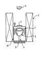
- a contactless fusion device by coupled levitation and electromagnetic and magnetic includes (figure) an inductor 1 placed in a superconductive coil 2 and surrounding a cold crucible 3.
- the cold crucible 3 is, for example, a hemispherical copper crucible segmented with an internal diameter of 16 mm, inserted in the inductor 1.
- the bottom crucible 3 is equipped with a retractable cooled finger 4, connected to a support horizontal 5 vertical translation.
- Inductor 1 is, for example, an inductor with four turns supplied with high frequency alternating current.
- the inductive system including inductor 1 and the cold crucible 3 is placed in a sealed enclosure 10, connected to a pump primary vacuum.
- This enclosure 10, resting on the support 5, is provided with a upper window 7 authorizing monitoring by video camera 6 of the phenomena producing in enclosure 10.
- Superconducting coil 2 has a 120 mm field hole in diameter and is capable of delivering a vertical magnetic field up to 8 T In the center.
- the enclosure 10 is inserted in the center of this coil 2.
- a solid sample is first placed in the cold crucible 3 and a vacuum is produced on this sample.
- a vacuum is produced on this sample.
- the force responsible for levitation consists of a component from the alternating magnetic field (repulsion between inductor and metallic charge) and a component from continuous magnetic field gradient related to the magnetic susceptibility of the material.
- the temperature of the sample is reduced while maintaining the total force of constant levitation.
- the decrease in temperature is obtained by progressive reduction of the field intensity magnetic alternating. This operation has two effects: a decrease in the electromagnetic component of the levitation force and a variation in the magnetic susceptibility (which is a function of temperature) which acts on the value of the magnetic component of the levitation force.
- Solidification without contact is therefore obtained by compensating in time real during cooling the variation of the levitation force by a variation in the intensity of the corresponding continuous magnetic field gradient.
- a infrared pyrometer preferably allows the temperature of the sample being processed. We can thus possibly determine the variations in the magnetic properties of the sample and combine them with the induction variations to determine the variation to apply to the field continuous magnetic, therefore at the induced gradient.
Landscapes
- Physics & Mathematics (AREA)
- Electromagnetism (AREA)
- Sampling And Sample Adjustment (AREA)
- Crystals, And After-Treatments Of Crystals (AREA)
- Glass Compositions (AREA)
- Investigating Or Analyzing Materials Using Thermal Means (AREA)
- Crucibles And Fluidized-Bed Furnaces (AREA)
- General Induction Heating (AREA)
Description
- dans une première étape, on fait fondre l'échantillon par induction au moyen d'un champ magnétique alternatif,
- dans une deuxième étape, on superpose au champ magnétique alternatif un gradient d'un champ magnétique continu, de manière à provoquer une lévitation de l'échantillon fondu sans contact avec des surfaces solides, et
- dans une troisième étape, on produit une solidification de l'échantillon.
- une lévitation qui soulève verticalement l'échantillon ; en le détachant ainsi de son support, on réduit les pertes thermiques par contact et on peut donc obtenir une surchauffe importante ; cet effet est particulièrement avantageux dans le cas d'un creuset froid, car des pertes thermiques par contact empêcheraient alors toute surchauffe ;
- et une réduction, voire un arrêt du brassage électromagnétique, ce qui stabilise la forme du liquide et fixe sa position, permettant de mettre en lévitation l'échantillon liquide de manière stable.
Claims (8)
- Procédé de fusion et de solidification d'un échantillon conducteur d'électricité dans lequel :caractérisé en ce que dans la deuxième étape, on ajuste l'intensité du champ magnétique alternatif de manière à obtenir une surchauffe de l'échantillon et en ce que dans la troisième étape, la réduction du champ magnétique alternatif est effectuée tout en faisant varier l'intensité du gradient du champ magnétique continu, de manière à maintenir l'échantillon en lévitation sans contact avec des surfaces solides, la réduction d'intensité du champ magnétique alternatif étant compensée par une variation adaptée d'intensité du gradient du champ magnétique continu, de façon à exercer sur l'échantillon une force de lévitation environ constante.dans une première étape, on fait fondre l'échantillon par induction au moyen d'un champ magnétique alternatif,dans une deuxième étape, on superpose au champ magnétique alternatif un gradient d'un champ magnétique continu, de manière à provoquer une lévitation de l'échantillon fondu sans contact avec des surfaces solides,dans une troisième étape, on produit une solidification sans contact de l'échantillon par réduction de l'intensité du champ magnétique alternatif pour diminuer la température de l'échantillon,
- Procédé de fusion et de solidification selon la revendication 1,
caractérisé en ce que ladite surchauffe est suffisante pour produire une surfusion de l'échantillon dans la troisième étape. - Procédé de fusion et de solidification selon la revendication 1 ou 2, caractérisé en ce qu'on dispose l'échantillon dans une zone de gradient du champ magnétique continu, ledit gradient ayant une intensité décroissant vers le haut
- Procédé de fusion et de solidification selon la revendication 1, 2
ou 3, caractérisé en ce que l'on applique un gradient de champ magnétique continu dès la première étape, de manière à provoquer une lévitation de l'échantillon et obtenir une fusion sans contact. - Procédé de fusion et de solidification selon la revendication 1, 2
ou 3, caractérisé en ce qu'on fait fondre l'échantillon dans un creuset froid (3). - Procédé de fusion et de solidification selon la revendication 5,
caractérisé en ce que le creuset froid (3) est inductif et est positionné dans une zone de gradient de champ magnétique continu d'un aimant supraconducteur (2), capable de produire sur l'échantillon une force verticale dirigée vers le haut. - Application du procédé selon l'une quelconque des revendications précédentes à la fabrication d'échantillons comprenant au moins une phase métastable.
- Application selon la revendication 7, caractérisée en ce que la phase métastable est à la base d'un alliage de titane, préférentiellement de TiAl.
Applications Claiming Priority (3)
| Application Number | Priority Date | Filing Date | Title |
|---|---|---|---|
| FR9912367 | 1999-10-04 | ||
| FR9912367A FR2799335B1 (fr) | 1999-10-04 | 1999-10-04 | Procede de fusion et de solidification sans contact d'un echantillon conducteur d'electricite |
| PCT/FR2000/002728 WO2001026424A1 (fr) | 1999-10-04 | 2000-10-02 | Procede de fusion et de solidification sans contact d'un echantillon conducteur d'electricite |
Publications (2)
| Publication Number | Publication Date |
|---|---|
| EP1222841A1 EP1222841A1 (fr) | 2002-07-17 |
| EP1222841B1 true EP1222841B1 (fr) | 2004-12-01 |
Family
ID=9550558
Family Applications (1)
| Application Number | Title | Priority Date | Filing Date |
|---|---|---|---|
| EP00966254A Expired - Lifetime EP1222841B1 (fr) | 1999-10-04 | 2000-10-02 | Procede de fusion et de solidification sans contact d'un echantillon conducteur d'electricite |
Country Status (8)
| Country | Link |
|---|---|
| EP (1) | EP1222841B1 (fr) |
| JP (1) | JP2003511239A (fr) |
| KR (1) | KR20020043611A (fr) |
| AT (1) | ATE284124T1 (fr) |
| AU (1) | AU7670300A (fr) |
| DE (1) | DE60016444D1 (fr) |
| FR (1) | FR2799335B1 (fr) |
| WO (1) | WO2001026424A1 (fr) |
Families Citing this family (6)
| Publication number | Priority date | Publication date | Assignee | Title |
|---|---|---|---|---|
| DE102009042972A1 (de) | 2009-09-16 | 2011-03-24 | Technische Universität Ilmenau | Vorrichtung und Verfahren zum Manipulieren einer levitierten elektrisch leitfähigen Substanz |
| DE102011018675A1 (de) | 2011-04-18 | 2012-10-18 | Technische Universität Ilmenau | Vorrichtung und Verfahren zum aktiven Manipulieren einer elektrisch leitfähigen Substanz |
| US10563275B2 (en) * | 2014-10-16 | 2020-02-18 | Glassy Metal, Llc | Method and apparatus for supercooling of metal/alloy melts and for the formation of amorphous metals therefrom |
| CN105970135B (zh) * | 2016-05-11 | 2019-02-22 | 上海大学 | 利用梯度强磁场制备梯度组成块体材料的方法和装置 |
| CN113758789B (zh) * | 2021-09-10 | 2022-07-22 | 西北工业大学 | 支撑加热金属样品的装置及系统 |
| CN113981273B (zh) * | 2021-11-04 | 2022-05-27 | 四川大学 | 一种初始凝固相为α相的多取向片层组织TiAl合金及其制备方法和应用 |
Family Cites Families (1)
| Publication number | Priority date | Publication date | Assignee | Title |
|---|---|---|---|---|
| EP0294913A3 (fr) * | 1987-06-12 | 1989-08-09 | Inductotherm Corp. | Alimentation de puissance multiphasée pour coulée continue en lévitation |
-
1999
- 1999-10-04 FR FR9912367A patent/FR2799335B1/fr not_active Expired - Lifetime
-
2000
- 2000-10-02 EP EP00966254A patent/EP1222841B1/fr not_active Expired - Lifetime
- 2000-10-02 KR KR1020027004369A patent/KR20020043611A/ko not_active Withdrawn
- 2000-10-02 DE DE60016444T patent/DE60016444D1/de not_active Expired - Lifetime
- 2000-10-02 JP JP2001528432A patent/JP2003511239A/ja not_active Withdrawn
- 2000-10-02 AT AT00966254T patent/ATE284124T1/de not_active IP Right Cessation
- 2000-10-02 AU AU76703/00A patent/AU7670300A/en not_active Abandoned
- 2000-10-02 WO PCT/FR2000/002728 patent/WO2001026424A1/fr not_active Ceased
Also Published As
| Publication number | Publication date |
|---|---|
| FR2799335A1 (fr) | 2001-04-06 |
| AU7670300A (en) | 2001-05-10 |
| ATE284124T1 (de) | 2004-12-15 |
| JP2003511239A (ja) | 2003-03-25 |
| KR20020043611A (ko) | 2002-06-10 |
| EP1222841A1 (fr) | 2002-07-17 |
| FR2799335B1 (fr) | 2001-12-14 |
| DE60016444D1 (de) | 2005-01-05 |
| WO2001026424A1 (fr) | 2001-04-12 |
Similar Documents
| Publication | Publication Date | Title |
|---|---|---|
| Xu et al. | Growth velocity-undercooling relationship and structure refinement mechanism of undercooled Ni-Cu alloys | |
| FR2688516A1 (fr) | Dispositif pour la fabrication de metaux et d'alliages de metaux de grande purete. | |
| FR2543980A1 (fr) | Procede de fabrication de materiaux semiconducteurs et four de traitement pour la mise en oeuvre de ce procede | |
| Wang et al. | Growth interface of CdZnTe grown from Te solution with THM technique under static magnetic field | |
| Jian et al. | Direct observation of the crystal-growth transition in undercooled silicon | |
| EP1222841A1 (fr) | Procede de fusion et de solidification sans contact d'un echantillon conducteur d'electricite | |
| Yu et al. | Si purification by removal of entrapped Al during electromagnetic solidification refining of Si-Al alloy | |
| CN112813282B (zh) | 一种去除高温合金中高密度夹杂物的方法 | |
| Liu et al. | Dendritic Si growth morphologies in highly undercooled Al–Si alloys | |
| EP0448482B1 (fr) | Procédé de préparation d'un corps magnétique orienté et texturé | |
| FR2707420A1 (fr) | Conducteur en aluminium de grande pureté utilisé à très basse température. | |
| CA2569755C (fr) | Installation d'affinage de silicium | |
| FR2711034A1 (fr) | Appareil de lévitation et de fusion et son procédé de fonctionnement. | |
| FR2591135A1 (fr) | Procede ameliore de reglage des conditions de coulee en continu. | |
| Liu et al. | Grain refinement and grain coarsening of undercooled Fe–Co alloy | |
| EP4246539A1 (fr) | Procédé de fabrication d'un aimant à partir d'aimants recyclés | |
| EP0450031B1 (fr) | Procede de preparation de materiaux magnetiques de tres haute qualite | |
| FR2665462A1 (fr) | Procede de cristallisation en presence de champ magnetique. | |
| EP1167586A1 (fr) | Procédé de cristallogenese avec champ magnetique | |
| EP0158563B1 (fr) | Procédé de fabrication non polluant de silicium massif à partir de silicium divisé | |
| Li et al. | Wettability Behavior of Si/C and Si–Sn Alloy/C System | |
| Lee et al. | Impurity segregation behavior in polycrystalline silicon ingot grown with variation of electron-beam power | |
| FR2927910A1 (fr) | Procede de cristallogenese d'un materiau electriquement conducteur a l'etat fondu. | |
| Kranert et al. | Assessment of residual melt removal as approach to reduce the top redzone of cast silicon ingots | |
| Alam et al. | Impact of the Seed Layer Morphology on the Initial Growth of HPMC‐Si Ingot |
Legal Events
| Date | Code | Title | Description |
|---|---|---|---|
| PUAI | Public reference made under article 153(3) epc to a published international application that has entered the european phase |
Free format text: ORIGINAL CODE: 0009012 |
|
| 17P | Request for examination filed |
Effective date: 20020506 |
|
| AK | Designated contracting states |
Kind code of ref document: A1 Designated state(s): AT BE CH CY DE DK ES FI FR GB GR IE IT LI LU MC NL PT SE |
|
| AX | Request for extension of the european patent |
Free format text: AL;LT;LV;MK;RO;SI |
|
| GRAP | Despatch of communication of intention to grant a patent |
Free format text: ORIGINAL CODE: EPIDOSNIGR1 |
|
| GRAS | Grant fee paid |
Free format text: ORIGINAL CODE: EPIDOSNIGR3 |
|
| GRAA | (expected) grant |
Free format text: ORIGINAL CODE: 0009210 |
|
| AK | Designated contracting states |
Kind code of ref document: B1 Designated state(s): AT BE CH CY DE DK ES FI FR GB GR IE IT LI LU MC NL PT SE |
|
| PG25 | Lapsed in a contracting state [announced via postgrant information from national office to epo] |
Ref country code: IT Free format text: LAPSE BECAUSE OF FAILURE TO SUBMIT A TRANSLATION OF THE DESCRIPTION OR TO PAY THE FEE WITHIN THE PRESCRIBED TIME-LIMIT;WARNING: LAPSES OF ITALIAN PATENTS WITH EFFECTIVE DATE BEFORE 2007 MAY HAVE OCCURRED AT ANY TIME BEFORE 2007. THE CORRECT EFFECTIVE DATE MAY BE DIFFERENT FROM THE ONE RECORDED. Effective date: 20041201 Ref country code: NL Free format text: LAPSE BECAUSE OF FAILURE TO SUBMIT A TRANSLATION OF THE DESCRIPTION OR TO PAY THE FEE WITHIN THE PRESCRIBED TIME-LIMIT Effective date: 20041201 Ref country code: AT Free format text: LAPSE BECAUSE OF FAILURE TO SUBMIT A TRANSLATION OF THE DESCRIPTION OR TO PAY THE FEE WITHIN THE PRESCRIBED TIME-LIMIT Effective date: 20041201 Ref country code: GB Free format text: LAPSE BECAUSE OF FAILURE TO SUBMIT A TRANSLATION OF THE DESCRIPTION OR TO PAY THE FEE WITHIN THE PRESCRIBED TIME-LIMIT Effective date: 20041201 Ref country code: FI Free format text: LAPSE BECAUSE OF FAILURE TO SUBMIT A TRANSLATION OF THE DESCRIPTION OR TO PAY THE FEE WITHIN THE PRESCRIBED TIME-LIMIT Effective date: 20041201 Ref country code: IE Free format text: LAPSE BECAUSE OF FAILURE TO SUBMIT A TRANSLATION OF THE DESCRIPTION OR TO PAY THE FEE WITHIN THE PRESCRIBED TIME-LIMIT Effective date: 20041201 |
|
| REG | Reference to a national code |
Ref country code: GB Ref legal event code: FG4D Free format text: NOT ENGLISH |
|
| REG | Reference to a national code |
Ref country code: CH Ref legal event code: EP |
|
| REG | Reference to a national code |
Ref country code: IE Ref legal event code: FG4D Free format text: FRENCH |
|
| REF | Corresponds to: |
Ref document number: 60016444 Country of ref document: DE Date of ref document: 20050105 Kind code of ref document: P |
|
| PG25 | Lapsed in a contracting state [announced via postgrant information from national office to epo] |
Ref country code: DK Free format text: LAPSE BECAUSE OF FAILURE TO SUBMIT A TRANSLATION OF THE DESCRIPTION OR TO PAY THE FEE WITHIN THE PRESCRIBED TIME-LIMIT Effective date: 20050301 Ref country code: GR Free format text: LAPSE BECAUSE OF FAILURE TO SUBMIT A TRANSLATION OF THE DESCRIPTION OR TO PAY THE FEE WITHIN THE PRESCRIBED TIME-LIMIT Effective date: 20050301 Ref country code: SE Free format text: LAPSE BECAUSE OF FAILURE TO SUBMIT A TRANSLATION OF THE DESCRIPTION OR TO PAY THE FEE WITHIN THE PRESCRIBED TIME-LIMIT Effective date: 20050301 |
|
| PG25 | Lapsed in a contracting state [announced via postgrant information from national office to epo] |
Ref country code: DE Free format text: LAPSE BECAUSE OF FAILURE TO SUBMIT A TRANSLATION OF THE DESCRIPTION OR TO PAY THE FEE WITHIN THE PRESCRIBED TIME-LIMIT Effective date: 20050302 |
|
| PG25 | Lapsed in a contracting state [announced via postgrant information from national office to epo] |
Ref country code: ES Free format text: LAPSE BECAUSE OF FAILURE TO SUBMIT A TRANSLATION OF THE DESCRIPTION OR TO PAY THE FEE WITHIN THE PRESCRIBED TIME-LIMIT Effective date: 20050312 |
|
| NLV1 | Nl: lapsed or annulled due to failure to fulfill the requirements of art. 29p and 29m of the patents act | ||
| GBV | Gb: ep patent (uk) treated as always having been void in accordance with gb section 77(7)/1977 [no translation filed] |
Effective date: 20041201 |
|
| REG | Reference to a national code |
Ref country code: IE Ref legal event code: FD4D |
|
| PG25 | Lapsed in a contracting state [announced via postgrant information from national office to epo] |
Ref country code: CY Free format text: LAPSE BECAUSE OF FAILURE TO SUBMIT A TRANSLATION OF THE DESCRIPTION OR TO PAY THE FEE WITHIN THE PRESCRIBED TIME-LIMIT Effective date: 20051002 |
|
| PLBE | No opposition filed within time limit |
Free format text: ORIGINAL CODE: 0009261 |
|
| STAA | Information on the status of an ep patent application or granted ep patent |
Free format text: STATUS: NO OPPOSITION FILED WITHIN TIME LIMIT |
|
| PG25 | Lapsed in a contracting state [announced via postgrant information from national office to epo] |
Ref country code: MC Free format text: LAPSE BECAUSE OF NON-PAYMENT OF DUE FEES Effective date: 20051031 Ref country code: LI Free format text: LAPSE BECAUSE OF NON-PAYMENT OF DUE FEES Effective date: 20051031 Ref country code: BE Free format text: LAPSE BECAUSE OF NON-PAYMENT OF DUE FEES Effective date: 20051031 Ref country code: LU Free format text: LAPSE BECAUSE OF NON-PAYMENT OF DUE FEES Effective date: 20051031 Ref country code: CH Free format text: LAPSE BECAUSE OF NON-PAYMENT OF DUE FEES Effective date: 20051031 |
|
| 26N | No opposition filed |
Effective date: 20050902 |
|
| REG | Reference to a national code |
Ref country code: CH Ref legal event code: PL |
|
| PG25 | Lapsed in a contracting state [announced via postgrant information from national office to epo] |
Ref country code: FR Free format text: LAPSE BECAUSE OF NON-PAYMENT OF DUE FEES Effective date: 20060630 |
|
| REG | Reference to a national code |
Ref country code: FR Ref legal event code: ST Effective date: 20060630 |
|
| BERE | Be: lapsed |
Owner name: CENTRE NATIONAL DE LA RECHERCHE SCIENTIFIQUE *CNRS Effective date: 20051031 |
|
| PG25 | Lapsed in a contracting state [announced via postgrant information from national office to epo] |
Ref country code: PT Free format text: LAPSE BECAUSE OF NON-PAYMENT OF DUE FEES Effective date: 20050501 |