EP1222542B1 - Fehlertolerantes verteiltes computersystem - Google Patents
Fehlertolerantes verteiltes computersystem Download PDFInfo
- Publication number
- EP1222542B1 EP1222542B1 EP00945429A EP00945429A EP1222542B1 EP 1222542 B1 EP1222542 B1 EP 1222542B1 EP 00945429 A EP00945429 A EP 00945429A EP 00945429 A EP00945429 A EP 00945429A EP 1222542 B1 EP1222542 B1 EP 1222542B1
- Authority
- EP
- European Patent Office
- Prior art keywords
- computer system
- computer
- distributor
- guardian
- node
- Prior art date
- Legal status (The legal status is an assumption and is not a legal conclusion. Google has not performed a legal analysis and makes no representation as to the accuracy of the status listed.)
- Expired - Lifetime
Links
Images

Classifications
-
- G—PHYSICS
- G06—COMPUTING; CALCULATING OR COUNTING
- G06F—ELECTRIC DIGITAL DATA PROCESSING
- G06F11/00—Error detection; Error correction; Monitoring
- G06F11/07—Responding to the occurrence of a fault, e.g. fault tolerance
- G06F11/16—Error detection or correction of the data by redundancy in hardware
- G06F11/20—Error detection or correction of the data by redundancy in hardware using active fault-masking, e.g. by switching out faulty elements or by switching in spare elements
- G06F11/2002—Error detection or correction of the data by redundancy in hardware using active fault-masking, e.g. by switching out faulty elements or by switching in spare elements where interconnections or communication control functionality are redundant
- G06F11/2005—Error detection or correction of the data by redundancy in hardware using active fault-masking, e.g. by switching out faulty elements or by switching in spare elements where interconnections or communication control functionality are redundant using redundant communication controllers
-
- H—ELECTRICITY
- H04—ELECTRIC COMMUNICATION TECHNIQUE
- H04L—TRANSMISSION OF DIGITAL INFORMATION, e.g. TELEGRAPHIC COMMUNICATION
- H04L12/00—Data switching networks
- H04L12/28—Data switching networks characterised by path configuration, e.g. LAN [Local Area Networks] or WAN [Wide Area Networks]
- H04L12/40—Bus networks
- H04L12/40006—Architecture of a communication node
- H04L12/40026—Details regarding a bus guardian
-
- H—ELECTRICITY
- H04—ELECTRIC COMMUNICATION TECHNIQUE
- H04L—TRANSMISSION OF DIGITAL INFORMATION, e.g. TELEGRAPHIC COMMUNICATION
- H04L12/00—Data switching networks
- H04L12/66—Arrangements for connecting between networks having differing types of switching systems, e.g. gateways
Definitions
- This invention relates to a fault-tolerant distributed computer system in which a plurality of node computers connected via at least one distribution unit, each node computer via an autonomous Communication control unit with the corresponding connections to the communication channels and access to the communication channels according to a cyclic time slicing method he follows.
- the invention relates to a distribution unit of a fault-tolerant distributed computer system, via which a plurality of node computers are connected to each other, each node computer via an autonomous communication control unit with associated connections to the Has communication channels and access to the communication channels accordingly a cyclic time slicing process takes place.
- a distributed fault tolerant real-time computer system consisting of a number of Node computers and a real-time communication system, must be the failure of a node computer be tolerated.
- a fault tolerant Real-time communication system for the predictably fast and secure exchange of News.
- the protocol TTP / C assumes that the communication system is a logical broadcast topology supported and that the node computers from the point of view of the receiver a "fail-silence" (Kopetz, p. 121) show failure behavior, i. either the node computers work correctly in the Range of values and in the time domain or they are quiet. This is described in Kopetz, H. (1997), “Real-Time Systems, Design Principles for Distributed Embedded Applications”; ISBN: 0-7923-9894-7, Boston, Kluwer Academic Publishers. The prevention of errors in the time domain, d. s. the so-called "Babbling Idiot" mistake (Kopetz, p.130 and Annual Int.
- a logical broadcast topology of the communication may be either through a physical distributed bus system, a distributed ring system, or by a distribution unit, e.g. one Star coupler, with point-to-point connections to the node computers or through a combination of these topologies. If a distributed bus system or a distributed Ring system is built, so each node computer must have its own Guardian.
- the object is achieved with a distributor unit of the type mentioned above, in which According to the invention, the distributor unit is set up, on the basis of its a priori known regular send behavior of the node computer to force a node computer only within Its statically assigned time slot connects to other node computers receives.
- the function of the distribution unit is based on the evaluation of a combination of static a Priori Information about the temporal transmission authorization of the individual node computers with a dynamic synchronization of the distribution unit by the messages of a timed Communication system.
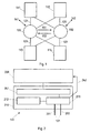
- an implementation of the invention is based on an example with four node computers, shown connected via two replicated manifolds.
- the objects in the Illustrations are numbered so that the first of the three-digit reference numbers is always on the picture number relates.
- each node computer forms a replaceable unit and is connected via a point-to-point connection 121 to two replicated distributor units 101 and 102 .
- a unidirectional communication channel 151 leads to the other second distribution unit 102.
- a unidirectional communication channel 152 leads to the distribution unit 101.
- Implied links 141 and 142 are dedicated communication channels; they lead to a maintenance computer, which can not be seen on the drawing, which can set the parameters of the distributor units and continuously monitor the correct functioning of the distributor units.
- Fig. 2 shows the internal structure of a node computer 111. It consists of two subsystems, namely a communication controller 210 which is connected to the replicated communication channels 201 and 202 (corresponding to 121 in Fig. 1), and a host computer 220 on which the application programs of the node computer. These two subsystems are interconnected via a communication network interface (CNI) 241 and a signal line 242 .
- the two subsystems exchange the communication data via this shared memory or interface 241 .
- the signal line 242 is used to transmit the synchronized time signals. This signal line is described in detail in the cited US 4,866,606 A.
- the communication controller 210 which operates autonomously, has a communication control unit 211 and a data structure 212 indicating at what times messages must be sent and received.
- the data structure 212 is referred to as Message Descriptor List
- Fig. 3 shows the structure of a distribution unit with integrated Guardian.
- a distribution unit consists of input ports 311, output ports 312, a data distributor 330 and a control computer 340 .
- the data links 301 from the hub computer (corresponding to 121 in FIG. 1) are routed to an input port 311 and an output port 312 of the hub.
- these two ports 311 and 312 can also be connected separately to corresponding ports of the node computer with the data connection 301 .
- each input port 311 is located - in addition to the usual filters and, if necessary, a potential separation - a switch 313, which can be controlled by the control computer 340 of the distribution unit via a signal line 314 and the control computer 340 tells when is received on this port.
- the data arriving at input port 311 is forwarded via data distributor 330 to output ports 312, to control computer 340 (via data line 331), and to other distribution units (via channel 351 ).
- the control computer 340 also has a serial I / O channel 341 through which the static data structure of FIG. 4 can be loaded and which periodically provides diagnostic information about the state of the control computer 340 to a service computer. If necessary, the data on lines 312 before the output can be amplified. Such prior art amplifiers are not included in FIG.
- This data structure contains for each port or node computer 111, 112, 113, 114 of the distribution unit has its own record 411, 412, 413, 414.
- a first field of this record 401 is the port number to which this record refers.
- a second field 402 is the transmission duration of the node connected to the port corresponding to the entry in the list MEDL 212.
- a third field 403 is the duration of the time interval between the end of the current transmission until the beginning of the next transmission of the port connected to the port node.
- a fourth field 404 is the number of the next temporal port.
- a fifth field 405 the duration of the time interval between the end of the current transmission until the beginning of the transmission of the node at the time-nearest port.
- Field 406 is the length of an initialization message that can be received on the current port.
- the content of the data structure of FIG. 4 is created by a development tool in coordination with the message descriptor lists 212 and loaded into the control computer 340 via channel 341 prior to runtime.
- Fig. 5 shows the structure of an initialization message.
- the initialization message must include in its header 501 an excellent bit 510 identifying the message as an initialization message.
- the data field 502 of the initialization message contains further information which is of no significance for the function of a simple distributor unit.
- the CRC field 503 is located at the end of the initialization message.
- the information in the data field 502 can evaluate an initialization message in addition to increasing the error detection probability. For example, such more powerful distribution units can evaluate the time field of a TTP / C initialization message in order to compare the clock status of the transmitter with the own clock.
- control computer 340 shows the two most important internal states of the control computer 340 of a distributor unit 101, unsynchronized 601 and synchronized 602.
- the control computer 340 enters the state "unsynchronized". In this state, all input ports 311 are connected to the data distributor 330 .
- control computer 340 determines via signal line 314 which port was received, stores the time of reception, checks the length of the message Comparison with the length stored in field 406 and, with a positive outcome of the test, goes into the state "synchronized" 602, wherein the stored reception time of the initialization message represents the synchronization event.
- the control computer 340 establishes a connection at the corresponding input port only during the period 403 . If, at approximately the right time, any message conforming to the encoding rules of the selected coding system arrives, then the control computer uses the measured time difference between the observed and expected time of arrival of the message to transmit its clock via a known fault tolerant algorithm (eg Kopetz 1997, p ) resynchronize. If during a priori specified time interval d fault-1 no correct message to any of the channels 301 arrives to 304 or 352, the distribution unit or its control computer 340 goes into the state "not synchronized" 601. In the synchronized state 602 is a message correctly, if it fulfills at least the following criteria: it arrives at the entry port at approximately the expected time, has a correct CRC field 503 and has the correct length corresponding to field 406 .
- a known fault tolerant algorithm eg Kopetz 1997, p
- the control computer 340 communicates over the I / O line 341 (these are the lines 141 and 142 in FIG. 1) with the maintenance computer, which performs the parameterization of the control computer 340 and monitors the operation of the control computer during operation.
- the incoming physical Signal in each distribution unit immediately after receiving using the local clock of the distribution unit converted into a logical signal ("digital signal") and again converted to the physical form immediately before transmission from the distribution unit (signal reshaping by the distribution unit).
- This maps a marginally incorrect coding into either a consistently correct coding or a consistently incorrect coding. Assuming that only one cause of error occurs within a TDMA round, this measure can prevent a single error in the time domain or in the value range from disturbing the coding on both channels in such a way that inconsistencies can occur in the system.
- control computer 340 can only effect the opening and closing of the switches 313, but does not change the contents of the messages being transmitted or insert new messages.
- the only type of failure of the distribution unit is therefore a fail-silent failure of a communication channel. In a fault-tolerant configuration, however, there is always a second independent communication channel.
- the invention does not relate to the described implementation limited to four node computers and two distribution units, but expandable as required. is. It is not only in the TTP / C protocol, but also in other timed protocols applicable.
Landscapes
- Engineering & Computer Science (AREA)
- Computer Networks & Wireless Communication (AREA)
- Signal Processing (AREA)
- Theoretical Computer Science (AREA)
- General Physics & Mathematics (AREA)
- General Engineering & Computer Science (AREA)
- Physics & Mathematics (AREA)
- Quality & Reliability (AREA)
- Computer And Data Communications (AREA)
- Hardware Redundancy (AREA)
- Multi Processors (AREA)
- Remote Monitoring And Control Of Power-Distribution Networks (AREA)
- Soil Working Implements (AREA)
- Stored Programmes (AREA)
Applications Claiming Priority (4)
| Application Number | Priority Date | Filing Date | Title |
|---|---|---|---|
| AT139599 | 1999-08-13 | ||
| AT0139599A AT407582B (de) | 1999-08-13 | 1999-08-13 | Nachrichtenverteilereinheit mit integriertem guardian zur verhinderung von ''babbling idiot'' fehlern |
| PCT/AT2000/000174 WO2001013230A1 (de) | 1999-08-13 | 2000-06-26 | Verfahren zum erzwingen der fail-silent eigenschaft in einem verteilten computersystem und verteilereinheit eines solchen systems |
| US10/071,991 US20030154427A1 (en) | 1999-08-13 | 2002-02-08 | Method for enforcing that the fail-silent property in a distributed computer system and distributor unit of such a system |
Publications (2)
| Publication Number | Publication Date |
|---|---|
| EP1222542A1 EP1222542A1 (de) | 2002-07-17 |
| EP1222542B1 true EP1222542B1 (de) | 2003-04-16 |
Family
ID=39428069
Family Applications (1)
| Application Number | Title | Priority Date | Filing Date |
|---|---|---|---|
| EP00945429A Expired - Lifetime EP1222542B1 (de) | 1999-08-13 | 2000-06-26 | Fehlertolerantes verteiltes computersystem |
Country Status (7)
| Country | Link |
|---|---|
| US (1) | US20030154427A1 (ja) |
| EP (1) | EP1222542B1 (ja) |
| JP (1) | JP4099332B2 (ja) |
| AT (2) | AT407582B (ja) |
| AU (1) | AU5952400A (ja) |
| DE (1) | DE50001819D1 (ja) |
| WO (1) | WO2001013230A1 (ja) |
Families Citing this family (39)
| Publication number | Priority date | Publication date | Assignee | Title |
|---|---|---|---|---|
| AT410490B (de) * | 2000-10-10 | 2003-05-26 | Fts Computertechnik Gmbh | Verfahren zur tolerierung von ''slightly-off- specification'' fehlern in einem verteilten fehlertoleranten echtzeitcomputersystem |
| AT411853B (de) * | 2001-06-06 | 2004-06-25 | Fts Computertechnik Gmbh | Sichere dynamische softwareallokation |
| DE10148325A1 (de) * | 2001-09-29 | 2003-04-17 | Daimler Chrysler Ag | Buswächtereinheit |
| DE10206875A1 (de) | 2002-02-18 | 2003-08-28 | Philips Intellectual Property | Verfahren und Schaltungsanordnung zum Überwachen und Verwalten des Datenverkehrs in einem Kommunikationssystem mit mehreren Kommunikationsknoten |
| FR2837641B1 (fr) * | 2002-03-21 | 2004-09-10 | Cit Alcatel | Reseau de telecommunications optiques de type metropolitain comprenant un coeur de type en anneau |
| GB2386804A (en) | 2002-03-22 | 2003-09-24 | Motorola Inc | Communications network node access switches |
| DE60301637T2 (de) * | 2002-04-16 | 2006-06-22 | Robert Bosch Gmbh | Verfahren zur Datenübertragung in einem Kommunikationssystem |
| AT411948B (de) | 2002-06-13 | 2004-07-26 | Fts Computertechnik Gmbh | Kommunikationsverfahren und apparat zur übertragung von zeitgesteuerten und ereignisgesteuerten ethernet nachrichten |
| ATE365410T1 (de) * | 2003-05-05 | 2007-07-15 | Koninkl Philips Electronics Nv | Fehlererkennung und unterdrückung in einem tdma- basierten netzknoten |
| DE10328707B4 (de) * | 2003-06-26 | 2013-10-02 | Bayerische Motoren Werke Aktiengesellschaft | Fail-Silent-Datenbus |
| GB2404827A (en) * | 2003-08-05 | 2005-02-09 | Motorola Inc | Fault containment at non-faulty processing nodes in TDMA networks |
| AT500565A2 (de) * | 2003-10-08 | 2006-01-15 | Tttech Computertechnik Ag | Verfahren und apparat zur realisierung einer zeitgesteuerten kommunikation |
| US7372859B2 (en) | 2003-11-19 | 2008-05-13 | Honeywell International Inc. | Self-checking pair on a braided ring network |
| JP2007515878A (ja) | 2003-11-19 | 2007-06-14 | ハネウェル・インターナショナル・インコーポレーテッド | 送信スケジュール実施用の投票機構 |
| EP1690377A2 (en) * | 2003-11-19 | 2006-08-16 | Honeywell International Inc. | Priority based arbitration for tdma schedule enforcement in a multi-channel system in star configuration |
| EP1704681A2 (en) * | 2003-11-19 | 2006-09-27 | Honeywell International, Inc. | Simplified time synchronization for a centralized guardian in a tdma star network |
| US7698395B2 (en) | 2003-11-19 | 2010-04-13 | Honeywell International Inc. | Controlling start up in a network |
| US7668204B2 (en) | 2003-11-19 | 2010-02-23 | Honeywell International Inc. | Port driven authentication in a network |
| US7502334B2 (en) | 2003-11-19 | 2009-03-10 | Honeywell International Inc. | Directional integrity enforcement in a bi-directional braided ring network |
| US7630390B2 (en) | 2003-11-19 | 2009-12-08 | Honeywell International Inc. | Asynchronous hub |
| AT501480B8 (de) | 2004-09-15 | 2007-02-15 | Tttech Computertechnik Ag | Verfahren zum erstellen von kommunikationsplänen für ein verteiltes echtzeit-computersystem |
| US8301885B2 (en) | 2006-01-27 | 2012-10-30 | Fts Computertechnik Gmbh | Time-controlled secure communication |
| US8315274B2 (en) | 2006-03-29 | 2012-11-20 | Honeywell International Inc. | System and method for supporting synchronous system communications and operations |
| US7668084B2 (en) | 2006-09-29 | 2010-02-23 | Honeywell International Inc. | Systems and methods for fault-tolerant high integrity data propagation using a half-duplex braided ring network |
| US7889683B2 (en) | 2006-11-03 | 2011-02-15 | Honeywell International Inc. | Non-destructive media access resolution for asynchronous traffic in a half-duplex braided-ring |
| US7912094B2 (en) | 2006-12-13 | 2011-03-22 | Honeywell International Inc. | Self-checking pair-based master/follower clock synchronization |
| US7656881B2 (en) | 2006-12-13 | 2010-02-02 | Honeywell International Inc. | Methods for expedited start-up and clique aggregation using self-checking node pairs on a ring network |
| DE102007016917B4 (de) * | 2007-04-05 | 2009-12-17 | Phoenix Contact Gmbh & Co. Kg | Verfahren sowie System zur sicheren Übertragung von zyklischen zu übertragenden Prozessdaten |
| EP2145431B1 (de) | 2007-04-11 | 2011-10-05 | FTS Computertechnik GmbH | Kommunikationsverfahren und apparat zur effizienten und sicheren übertragung von tt-ethernet nachrichten |
| US8204037B2 (en) * | 2007-08-28 | 2012-06-19 | Honeywell International Inc. | Autocratic low complexity gateway/ guardian strategy and/or simple local guardian strategy for flexray or other distributed time-triggered protocol |
| US7778159B2 (en) | 2007-09-27 | 2010-08-17 | Honeywell International Inc. | High-integrity self-test in a network having a braided-ring topology |
| US8817597B2 (en) | 2007-11-05 | 2014-08-26 | Honeywell International Inc. | Efficient triple modular redundancy on a braided ring |
| AT507125B1 (de) | 2008-07-25 | 2010-05-15 | Tttech Computertechnik Ag | Multirouter für zeitgesteuerte kommunikationssysteme |
| DE102011016706A1 (de) * | 2011-04-11 | 2012-10-11 | Conti Temic Microelectronic Gmbh | Schaltungsanordnung mit Fail-Silent-Funktion |
| US8498276B2 (en) | 2011-05-27 | 2013-07-30 | Honeywell International Inc. | Guardian scrubbing strategy for distributed time-triggered protocols |
| US9201719B2 (en) * | 2012-03-16 | 2015-12-01 | Infineon Technologies Ag | Method and system for timeout monitoring |
| FR2996091B1 (fr) * | 2012-09-21 | 2015-07-17 | Thales Sa | Noeud fonctionnel pour un reseau de transmission d'informations et reseau correspondant |
| US9921637B2 (en) * | 2015-10-26 | 2018-03-20 | Nxp Usa, Inc. | Multi-port power prediction for power management of data storage devices |
| US11637776B2 (en) * | 2021-04-27 | 2023-04-25 | Realtek Singapore Pte Ltd. | Network device and packet replication method |
Family Cites Families (7)
| Publication number | Priority date | Publication date | Assignee | Title |
|---|---|---|---|---|
| US4228496A (en) * | 1976-09-07 | 1980-10-14 | Tandem Computers Incorporated | Multiprocessor system |
| AT382253B (de) * | 1984-06-22 | 1987-02-10 | Austria Mikrosysteme Int | Lose gekoppeltes verteiltes computersystem |
| US4860285A (en) * | 1987-10-21 | 1989-08-22 | Advanced Micro Devices, Inc. | Master/slave synchronizer |
| AU7453491A (en) * | 1990-03-29 | 1991-10-21 | Sf2 Corporation | Method and apparatus for scheduling access to a csma communication medium |
| US5694542A (en) * | 1995-11-24 | 1997-12-02 | Fault Tolerant Systems Fts-Computertechnik Ges.M.B. | Time-triggered communication control unit and communication method |
| US6618363B1 (en) * | 1998-10-09 | 2003-09-09 | Microsoft Corporation | Method for adapting video packet generation and transmission rates to available resources in a communications network |
| EP1320960B1 (en) * | 2000-09-28 | 2013-11-06 | Symantec Corporation | System and method for analyzing protocol streams for a security-related event |
-
1999
- 1999-08-13 AT AT0139599A patent/AT407582B/de not_active IP Right Cessation
-
2000
- 2000-06-26 WO PCT/AT2000/000174 patent/WO2001013230A1/de active IP Right Grant
- 2000-06-26 JP JP2001517259A patent/JP4099332B2/ja not_active Expired - Lifetime
- 2000-06-26 EP EP00945429A patent/EP1222542B1/de not_active Expired - Lifetime
- 2000-06-26 AU AU59524/00A patent/AU5952400A/en not_active Abandoned
- 2000-06-26 AT AT00945429T patent/ATE237841T1/de not_active IP Right Cessation
- 2000-06-26 DE DE50001819T patent/DE50001819D1/de not_active Expired - Lifetime
-
2002
- 2002-02-08 US US10/071,991 patent/US20030154427A1/en not_active Abandoned
Also Published As
| Publication number | Publication date |
|---|---|
| EP1222542A1 (de) | 2002-07-17 |
| DE50001819D1 (de) | 2003-05-22 |
| US20030154427A1 (en) | 2003-08-14 |
| JP2003507790A (ja) | 2003-02-25 |
| AU5952400A (en) | 2001-03-13 |
| JP4099332B2 (ja) | 2008-06-11 |
| ATE237841T1 (de) | 2003-05-15 |
| AT407582B (de) | 2001-04-25 |
| ATA139599A (de) | 2000-08-15 |
| WO2001013230A1 (de) | 2001-02-22 |
Similar Documents
| Publication | Publication Date | Title |
|---|---|---|
| EP1222542B1 (de) | Fehlertolerantes verteiltes computersystem | |
| EP2145431B1 (de) | Kommunikationsverfahren und apparat zur effizienten und sicheren übertragung von tt-ethernet nachrichten | |
| EP0732654B1 (de) | Verfahren zur fehlertoleranten Kommunikation unter hohen Echtzeitbedingungen | |
| DE60133747T2 (de) | Versicherte ethernet backplane übertragung | |
| DE69610877T2 (de) | Netzwerkknoten mit Auswähler für ein verteiltes Steuerungssystem | |
| EP2169882B1 (de) | Schiffsruder-Steuerung mit einem CAN-Bus | |
| DE2908316A1 (de) | Multikonfigurierbares modulares verarbeitungssystem, das mit einem vorverarbeitungssystem integriert ist | |
| DE3103873A1 (de) | Raeumlich verteiltes datenverarbeitungssystem | |
| EP0144403B1 (de) | Verfahren und anordnung zum übertragen von informationen in einem datenring | |
| EP0658257B1 (de) | Kommunikationskontrolleinheit und verfahren zur übermittlung von nachrichten | |
| DE19728061C2 (de) | Verfahren zur Steuerung der Nutzung von Satelliten-Übertragungskapazität zum Ersetzen gestörter Datenleitungen in terrestrischen Netzen und Schaltungsanordnung zur Durchführung des Verfahrens | |
| DE05009511T1 (de) | Block-orientiertes Steuersystem auf Hochgeschwindigkeits-Ethernet | |
| AT410491B (de) | Kommunikationsverfahren zur realisierung von ereigniskanälen in einem zeitgesteuerten kommunikationssystem | |
| DE60104465T2 (de) | Verfahren und Vorrichtung zur Verteilung eines Synchronisationssignales in einem Nachrichtenübertragungsnetzwerk | |
| EP1484679B1 (de) | Sicherstellung von maximalen Reaktionszeiten in komplexen oder verteilten sicheren und/oder nicht sicheren Systemen | |
| EP1399818B1 (de) | Verfahren und vorrichtung zur kommunikation in einem fehlertoleranten verteilten computersystem | |
| DE3041566A1 (de) | Verfahren und schaltungsanordnung zum uebertragen von datensignalen zwischen datenvermittlungseinrichtungen einer datenvermittlungsanlage | |
| DE69021626T2 (de) | Eingebettete Steuertechnik für verteilte Steuersysteme. | |
| EP1121785A2 (de) | Netzwerk sowie koppelgerät zur verbindung zweier segmente in einem derartigen netzwerk | |
| EP1179920A2 (de) | Datenbus für mehrere Teilnehmer | |
| DE3136524C2 (ja) | ||
| DE19753288A1 (de) | Effizientes Quittungsverfahren in einem verteilten zeitgesteuerten Echtzeitsystem | |
| EP1116360A2 (de) | Netzwerk sowie koppelgerät zur verbindung zweier segmente in einem derartigen netzwerk | |
| EP1535156B1 (de) | Verfahren und apparat zur fehlererkennung in einem verteilten echtzeitcomputersystem | |
| EP0974215A2 (de) | Datenkommunikationsverbindung in hierarchischem kommunikationsnetz mit bus, die nach einem abfrage/antwort-protokoll, dem sogenannten polling-protokoll, betrieben wird |
Legal Events
| Date | Code | Title | Description |
|---|---|---|---|
| PUAI | Public reference made under article 153(3) epc to a published international application that has entered the european phase |
Free format text: ORIGINAL CODE: 0009012 |
|
| 17P | Request for examination filed |
Effective date: 20020305 |
|
| AK | Designated contracting states |
Kind code of ref document: A1 Designated state(s): AT BE CH CY DE DK ES FI FR GB GR IE IT LI LU MC NL PT SE |
|
| AX | Request for extension of the european patent |
Free format text: AL;LT;LV;MK;RO;SI |
|
| GRAH | Despatch of communication of intention to grant a patent |
Free format text: ORIGINAL CODE: EPIDOS IGRA |
|
| RTI1 | Title (correction) |
Free format text: FAULT-TOLERANT DISTRIBUTED COMPUTER SYSTEM |
|
| GRAH | Despatch of communication of intention to grant a patent |
Free format text: ORIGINAL CODE: EPIDOS IGRA |
|
| GRAA | (expected) grant |
Free format text: ORIGINAL CODE: 0009210 |
|
| AK | Designated contracting states |
Designated state(s): AT BE CH CY DE DK ES FI FR GB GR IE IT LI LU MC NL PT SE |
|
| PG25 | Lapsed in a contracting state [announced via postgrant information from national office to epo] |
Ref country code: IE Free format text: LAPSE BECAUSE OF NON-PAYMENT OF DUE FEES Effective date: 20030416 Ref country code: FI Free format text: LAPSE BECAUSE OF FAILURE TO SUBMIT A TRANSLATION OF THE DESCRIPTION OR TO PAY THE FEE WITHIN THE PRESCRIBED TIME-LIMIT Effective date: 20030416 Ref country code: NL Free format text: LAPSE BECAUSE OF FAILURE TO SUBMIT A TRANSLATION OF THE DESCRIPTION OR TO PAY THE FEE WITHIN THE PRESCRIBED TIME-LIMIT Effective date: 20030416 |
|
| REG | Reference to a national code |
Ref country code: GB Ref legal event code: FG4D Free format text: NOT ENGLISH |
|
| REG | Reference to a national code |
Ref country code: CH Ref legal event code: EP |
|
| REF | Corresponds to: |
Ref document number: 50001819 Country of ref document: DE Date of ref document: 20030522 Kind code of ref document: P |
|
| REG | Reference to a national code |
Ref country code: IE Ref legal event code: FG4D Free format text: GERMAN |
|
| GBT | Gb: translation of ep patent filed (gb section 77(6)(a)/1977) | ||
| PG25 | Lapsed in a contracting state [announced via postgrant information from national office to epo] |
Ref country code: CY Free format text: LAPSE BECAUSE OF FAILURE TO SUBMIT A TRANSLATION OF THE DESCRIPTION OR TO PAY THE FEE WITHIN THE PRESCRIBED TIME-LIMIT Effective date: 20030626 Ref country code: LU Free format text: LAPSE BECAUSE OF NON-PAYMENT OF DUE FEES Effective date: 20030626 |
|
| PG25 | Lapsed in a contracting state [announced via postgrant information from national office to epo] |
Ref country code: MC Free format text: LAPSE BECAUSE OF NON-PAYMENT OF DUE FEES Effective date: 20030630 |
|
| REG | Reference to a national code |
Ref country code: SE Ref legal event code: TRGR |
|
| PG25 | Lapsed in a contracting state [announced via postgrant information from national office to epo] |
Ref country code: DK Free format text: LAPSE BECAUSE OF FAILURE TO SUBMIT A TRANSLATION OF THE DESCRIPTION OR TO PAY THE FEE WITHIN THE PRESCRIBED TIME-LIMIT Effective date: 20030716 Ref country code: PT Free format text: LAPSE BECAUSE OF FAILURE TO SUBMIT A TRANSLATION OF THE DESCRIPTION OR TO PAY THE FEE WITHIN THE PRESCRIBED TIME-LIMIT Effective date: 20030716 Ref country code: GR Free format text: LAPSE BECAUSE OF FAILURE TO SUBMIT A TRANSLATION OF THE DESCRIPTION OR TO PAY THE FEE WITHIN THE PRESCRIBED TIME-LIMIT Effective date: 20030716 |
|
| LTIE | Lt: invalidation of european patent or patent extension |
Effective date: 20030416 |
|
| NLV1 | Nl: lapsed or annulled due to failure to fulfill the requirements of art. 29p and 29m of the patents act | ||
| PG25 | Lapsed in a contracting state [announced via postgrant information from national office to epo] |
Ref country code: ES Free format text: LAPSE BECAUSE OF FAILURE TO SUBMIT A TRANSLATION OF THE DESCRIPTION OR TO PAY THE FEE WITHIN THE PRESCRIBED TIME-LIMIT Effective date: 20031030 |
|
| PGFP | Annual fee paid to national office [announced via postgrant information from national office to epo] |
Ref country code: AT Payment date: 20031031 Year of fee payment: 4 |
|
| REG | Reference to a national code |
Ref country code: IE Ref legal event code: FD4D Ref document number: 1222542E Country of ref document: IE |
|
| PLBI | Opposition filed |
Free format text: ORIGINAL CODE: 0009260 |
|
| BERE | Be: lapsed |
Owner name: *FTS COMPUTERTECHNIK G.M.B.H. Effective date: 20030630 |
|
| ET | Fr: translation filed | ||
| 26 | Opposition filed |
Opponent name: DAIMLERCHRYSLER AG Effective date: 20031127 |
|
| PLAX | Notice of opposition and request to file observation + time limit sent |
Free format text: ORIGINAL CODE: EPIDOSNOBS2 |
|
| PG25 | Lapsed in a contracting state [announced via postgrant information from national office to epo] |
Ref country code: AT Free format text: LAPSE BECAUSE OF NON-PAYMENT OF DUE FEES Effective date: 20040626 |
|
| PLBB | Reply of patent proprietor to notice(s) of opposition received |
Free format text: ORIGINAL CODE: EPIDOSNOBS3 |
|
| PG25 | Lapsed in a contracting state [announced via postgrant information from national office to epo] |
Ref country code: LI Free format text: LAPSE BECAUSE OF NON-PAYMENT OF DUE FEES Effective date: 20040630 Ref country code: CH Free format text: LAPSE BECAUSE OF NON-PAYMENT OF DUE FEES Effective date: 20040630 |
|
| REG | Reference to a national code |
Ref country code: CH Ref legal event code: PL |
|
| PG25 | Lapsed in a contracting state [announced via postgrant information from national office to epo] |
Ref country code: IT Free format text: LAPSE BECAUSE OF NON-PAYMENT OF DUE FEES Effective date: 20050626 |
|
| PLCK | Communication despatched that opposition was rejected |
Free format text: ORIGINAL CODE: EPIDOSNREJ1 |
|
| PLBN | Opposition rejected |
Free format text: ORIGINAL CODE: 0009273 |
|
| STAA | Information on the status of an ep patent application or granted ep patent |
Free format text: STATUS: OPPOSITION REJECTED |
|
| 27O | Opposition rejected |
Effective date: 20060306 |
|
| PG25 | Lapsed in a contracting state [announced via postgrant information from national office to epo] |
Ref country code: BE Free format text: LAPSE BECAUSE OF NON-PAYMENT OF DUE FEES Effective date: 20030630 |
|
| PGRI | Patent reinstated in contracting state [announced from national office to epo] |
Ref country code: IT Effective date: 20091201 |
|
| REG | Reference to a national code |
Ref country code: FR Ref legal event code: PLFP Year of fee payment: 16 |
|
| REG | Reference to a national code |
Ref country code: FR Ref legal event code: PLFP Year of fee payment: 17 |
|
| REG | Reference to a national code |
Ref country code: FR Ref legal event code: PLFP Year of fee payment: 18 |
|
| REG | Reference to a national code |
Ref country code: FR Ref legal event code: PLFP Year of fee payment: 19 |
|
| REG | Reference to a national code |
Ref country code: DE Ref legal event code: R082 Ref document number: 50001819 Country of ref document: DE Representative=s name: PATENTANWAELTE DIPL.-ING. W. JACKISCH & PARTNE, DE Ref country code: DE Ref legal event code: R082 Ref document number: 50001819 Country of ref document: DE Representative=s name: PATENTANWAELTE DIPL.-ING. WALTER JACKISCH & PA, DE Ref country code: DE Ref legal event code: R081 Ref document number: 50001819 Country of ref document: DE Owner name: TTTECH COMPUTERTECHNIK AG, AT Free format text: FORMER OWNER: FTS COMPUTERTECHNIK GES.M.B.H., BADEN-SIEGENFELD, AT |
|
| REG | Reference to a national code |
Ref country code: GB Ref legal event code: 732E Free format text: REGISTERED BETWEEN 20181025 AND 20181102 |
|
| PGFP | Annual fee paid to national office [announced via postgrant information from national office to epo] |
Ref country code: DE Payment date: 20190619 Year of fee payment: 20 Ref country code: IT Payment date: 20190624 Year of fee payment: 20 |
|
| PGFP | Annual fee paid to national office [announced via postgrant information from national office to epo] |
Ref country code: SE Payment date: 20190619 Year of fee payment: 20 Ref country code: FR Payment date: 20190619 Year of fee payment: 20 |
|
| PGFP | Annual fee paid to national office [announced via postgrant information from national office to epo] |
Ref country code: GB Payment date: 20190619 Year of fee payment: 20 |
|
| REG | Reference to a national code |
Ref country code: DE Ref legal event code: R071 Ref document number: 50001819 Country of ref document: DE |
|
| REG | Reference to a national code |
Ref country code: GB Ref legal event code: PE20 Expiry date: 20200625 |
|
| REG | Reference to a national code |
Ref country code: SE Ref legal event code: EUG |
|
| PG25 | Lapsed in a contracting state [announced via postgrant information from national office to epo] |
Ref country code: GB Free format text: LAPSE BECAUSE OF EXPIRATION OF PROTECTION Effective date: 20200625 |