EP1222061B1 - Device and method for disaggregating derived timber products - Google Patents
Device and method for disaggregating derived timber products Download PDFInfo
- Publication number
- EP1222061B1 EP1222061B1 EP00942095A EP00942095A EP1222061B1 EP 1222061 B1 EP1222061 B1 EP 1222061B1 EP 00942095 A EP00942095 A EP 00942095A EP 00942095 A EP00942095 A EP 00942095A EP 1222061 B1 EP1222061 B1 EP 1222061B1
- Authority
- EP
- European Patent Office
- Prior art keywords
- packing
- screws
- steam
- screw
- opening
- Prior art date
- Legal status (The legal status is an assumption and is not a legal conclusion. Google has not performed a legal analysis and makes no representation as to the accuracy of the status listed.)
- Expired - Lifetime
Links
Images
Classifications
-
- B—PERFORMING OPERATIONS; TRANSPORTING
- B27—WORKING OR PRESERVING WOOD OR SIMILAR MATERIAL; NAILING OR STAPLING MACHINES IN GENERAL
- B27N—MANUFACTURE BY DRY PROCESSES OF ARTICLES, WITH OR WITHOUT ORGANIC BINDING AGENTS, MADE FROM PARTICLES OR FIBRES CONSISTING OF WOOD OR OTHER LIGNOCELLULOSIC OR LIKE ORGANIC MATERIAL
- B27N3/00—Manufacture of substantially flat articles, e.g. boards, from particles or fibres
- B27N3/007—Manufacture of substantially flat articles, e.g. boards, from particles or fibres and at least partly composed of recycled material
-
- B—PERFORMING OPERATIONS; TRANSPORTING
- B27—WORKING OR PRESERVING WOOD OR SIMILAR MATERIAL; NAILING OR STAPLING MACHINES IN GENERAL
- B27N—MANUFACTURE BY DRY PROCESSES OF ARTICLES, WITH OR WITHOUT ORGANIC BINDING AGENTS, MADE FROM PARTICLES OR FIBRES CONSISTING OF WOOD OR OTHER LIGNOCELLULOSIC OR LIKE ORGANIC MATERIAL
- B27N1/00—Pretreatment of moulding material
Definitions
- the present invention relates to a device for the digestion of wood-based materials according to the Preamble of the main claim as well as a procedure its implementation.
- Such a generic device is known (US-A-3,741,863).
- A serves in this device trained as at least one stuffing screw Transport device for transporting the Digestion material, this one in a Outer jacket arranged discharge opening radially is transported. Furthermore, the feed opening the first stuffing auger as Inlet opening (77) used for steam.
- the disadvantage of this known device Need besides the stuffing augers Seals in the form of a rotary valve (72) in front of the Provide feed opening of the first stuffing screw and in the form of a cyclone separator after the last one To provide a stuffing screw, creating such facilities are expensive.
- the object of the present invention is a Generic device and a method create a continuous and therefore simple and economical digestion of Enable wood-based materials.
- the device can that is, both economically and ecologically Respect to be operated optimally.
- digestion pressures from 2 to 11 bar Maintain overpressure, preferably in Range from 2 to 8 bar and especially in the range from 3 to 6 bar overpressure.
- the digestion process from the filling with the crushed chipboard fragments up to completely digested, moist wood mass is done with several, at least three in a row switched snails.
- This pressure tight Darning augers perform several functions: both the transportation as well as the continuous Crushing and hydrolysis of the pre-swollen Mass of wood on the one hand due to the friction of the particles to each other, and on the other hand the actual one takes place Digestion process by water, steam and Heat absorption within the pipe screw system.
- a modular construction is possible, whereby several identical screws and also drive systems can be used, making the cost crucial reduced.
- the first has proven to be useful Darning screw into which the material to be digested is introduced with preheated water fill.
- a water temperature of approx. 20 ° C to 95 ° C can be used.
- the screw transport within the plant enables a homogenization of the wood mass and about the constant rubbing together during the Transports a good and continuous Size reduction, which is a good surface wetting causes. This can cause the enthalpy of the steam to over the entire pipe length can be fully used, because the rubbing against each other always Detach loosened layers mechanically and underneath expose lying, not yet solved layers that then easily caught by the steam. About The process can process higher process pressures again be accelerated.
- the exhaust gas heat can be used almost completely and is compared to discontinuous operation not lost according to the state of the art.
- the heat the moist, open wood mass can can also be used by after leaving from the last screw conveyor shortest way into the dryer. Thereby heat loss and drying effort minimized.
- stuffing snails are thus used, which make it possible during the Material transport a pressure in too build up transporting material.
- Such Snails also known as stuffing snails are, for example, one-sided Snails, the outlet opening of which runs axially. she can be a progressive or degressive slope have, that is, the distances between the coils increase or decrease per turn.
- the transport speed through the stuffing augers is different, it can depend on the Vary the number of stuffing screws used. at a larger number of stuffing screws can Throughput speed can be increased at a smaller number, it must be reduced in order to dwell time necessary for the digestion guarantee.
- the digestion can generally follow a Residence time approx. 30 min, preferably 20 min are completely effected so that when using more than three stuffing screws the dwell time per Darning screw is only a few minutes. Across from conventional discontinuous digestion processes this means a significant shortening of the Digestion time.
- the water temperatures can be 20 to 95 ° C.
- the water causes in Interaction with the abandoned wood materials an additional seal for the digestion overpressure used compared to Outside atmosphere.
- the first stuffing screw is advantageously turned on the feed side of the material with a high pressure lock equipped. On the exit side is one Pressure control is not absolutely necessary since here the pressure can drop to ambient pressure.
- the stuffing snails all had one 400 mm in diameter and 2.5 m in length. The It was driven by an electric motor uniform power of 10 kW. The first Darning screw was with a high pressure lock Fill level indicator provided.
- Chipboard material which had been comminuted to a particle size of approximately 8x8x20 cm 3 was introduced into the first stuffing screw.
- the screw was filled with preheated water, which had a temperature of approx. 90 ° C.
- the feed speed of the stuffing augers was like this controlled that a dwell time of approx. 5 min. resulted in each stuffing screw.
- the third stuffing screw became saturated steam with a Pressure of 4 bar overpressure metered in.
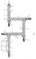
- the device shown in Figure 1 contains five in a row arranged augers 1, 2, 3, 4 and 5, which are driven by drive motors 6.
- the axial exit area of each screw is axial Direction perpendicular to the entrance area of the flanged subsequent stuffing screw, whereby pressure-tight connections are used.
- the Darning screw 3 contains a steam supply 7, the is connected to a saturated steam source (not shown).
- the stuffing screw 1 contains a feed device 8 for entering the digestion material.
- At the The end of the last screw 5 is either one Vapor suction device or a spring cover 9 arranged.
- the device shown in Fig. 1 has overall five pressure or so-called stuffing screws 1, 2, 3, 4, 5, each by drive motors 6 are driven. At the first snail the supply of those that have preferably already broken Wood material pieces as material feed. At the last snail 5 is an end Dispensing opening provided with a spring cover.
- the five stuffing screws are arranged one behind the other and serve both as a digestion container and as Transport device for the wood-based material pieces.
- Each stuffing screw has a housing-fixed Outer jacket 10 and an arranged therein drivable shaft 11 arranged around it Coils 12 of a predeterminable slope. Between the gears of the spirals on the one hand and between the (inner) shaft and the (outer) outer jacket the particles are transported.
- the stuffing snails 2, 3, 4, and 5 indicate when reproduced Embodiment the same, each other but possibly different slopes of the Spirals up.
- the stuffing screw 1 has coils 13 changing diameter or pitch.
- the pressure screw and the stuffing screw 3 are each arranged horizontally.
- stuffing screws 2 and 4 are angled, preferably arranged vertically.
- the individual stuffing augers are like this connected in series that the Wood material pieces in the axial direction (Transport direction) 14 of the stuffing screw from the Feed opening 15 in the outer jacket 10 to one frontal discharge opening 16 in the axial direction are transported, being between the Feed opening and the discharge opening in the outer jacket 10 in the stuffing screw 3, the inlet opening 7 for Steam is provided.
- the stuffing screw 2 can with an inlet opening 17 for water, preferably Be equipped with hot water. All stuffing snails, or at least part of it can be heated be designed.
Abstract
Description
Die vorliegende Erfindung betrifft eine Vorrichtung zum Aufschluss von Holzwerkstoffen gemäss dem Oberbegriff des Hauptanspruchs sowie ein Verfahren zu dessen Durchführung.The present invention relates to a device for the digestion of wood-based materials according to the Preamble of the main claim as well as a procedure its implementation.
Eine solche gattungsgemäße Vorrichtung ist bekannt (US-A-3,741,863). In dieser Vorrichtung dient eine als zumindest eine Stopfschnecke ausgebildete Transporteinrichtung zum Transport des Aufschlussmaterials, wobei dieses zu einer im Außenmantel angeordneten Abgabeöffnung radial transportiert wird. Ferner wird die Zuführöffnung der ersten Stopfschnecke zugleich als Einleitungsöffnung (77) für Dampf verwendet. Nachteilig ist bei dieser bekannten Vorrichtung die Notwendigkeit, außer den Stopfschnecken weitere Abdichtungen in Form eines Drehventils (72) vor der Zuführöffnung der ersten Stopfschnecke vorzusehen und in Form eines Zyklon-Trenners nach der letzten Stopfschnecke vorzusehen, wodurch solche Anlagen aufwendig sind.Such a generic device is known (US-A-3,741,863). A serves in this device trained as at least one stuffing screw Transport device for transporting the Digestion material, this one in a Outer jacket arranged discharge opening radially is transported. Furthermore, the feed opening the first stuffing auger as Inlet opening (77) used for steam. The disadvantage of this known device Need, besides the stuffing augers Seals in the form of a rotary valve (72) in front of the Provide feed opening of the first stuffing screw and in the form of a cyclone separator after the last one To provide a stuffing screw, creating such facilities are expensive.
Es ist ferner bekannt (DE 198 19 988 A1), eine als Förderschnecke ausgebildete Transporteinrichtung zum Transport des Aufschlussmaterials durch den Imprägnier- und vorquellschacht einzusetzen, während die zweite Förderschnecke zum Transport des bereits aufgeschlossenen Materials aus dem Aufschlussschacht dient. Im eigentlichen Aufschlussschacht wird das Aufschlussmaterial nicht durch Förderschnecken transportiert. Die Vorrichtung hat den Nachteil, dass beim Aufschluss unter Druck der Befüllungsschacht durch geeignete Maßnahme druckdicht verschliessbar sein muss. Auch der Austrag des aufgeschlossenen Materials muss geeignet druckdicht ausgebildet sein.It is also known (DE 198 19 988 A1), one as Conveyor screw designed transport device for Transport of the digestion material through the Use impregnation and pre-swell shaft while the second screw conveyor for transporting the digested material from the digestion shaft serves. In the actual digestion shaft, that is Digestion material not by screw conveyors transported. The device has the disadvantage that when digestion under pressure the filling shaft can be closed pressure-tight by suitable measures have to be. Also the discharge of the open-minded The material must be suitably pressure-tight.
Aufgabe der vorliegenden Erfindung ist es, eine gattungsgemäße Vorrichtung sowie ein Verfahren zu schaffen, die einen kontinuierlichen und damit einfachen und wirtschaftlichen Aufschluss von Holzwerkstoffen ermöglichen.The object of the present invention is a Generic device and a method create a continuous and therefore simple and economical digestion of Enable wood-based materials.
Gelöst wird diese Aufgabe durch eine gattungsgemäße Vorrichtung sowie ein gattungsgemäßes Verfahren durch den Gegenstand des Verfahrens- bzw. Vorrichtungshauptanspruchs.This task is solved by a generic Device and a generic method by the subject of the procedural or Device main claim.
Es wurde überraschenderweise gefunden, dass eine Anordnung von mindestens drei Stopfschnecken hintereinander ein Durchleiten von Aufschlussmaterial ermöglicht, wobei das Füllgut die zumindest drei Stopfschnecken soweit abdichtet, dass das Aufschlussverfahren auch unter Druck durchgeführt werden kann. Dabei wird Dampf vorzugsweise unter Überdruck, bspw. Druck von mindestens 2 bar über eine zwischen der Zuführöffnung und der Abgabeöffnung im Außenmantel vorgesehenen Einleitungsöffnung für den Dampf in eine der Stopfschnecken eingeleitet, die nicht die erste oder die letzte der Stopfschnecken-Anordnung ist. Dabei kann in den randseitigen Stopfschnecken zwar ein Druckabfall beobachtet werden, der bis zum atmosphärischen Druck abfallen kann, wobei aber im mittleren Teil die Anordnung zur Aufrechterhaltung eines Arbeitsdrucks führt, der bis zu 11 bar Überdruck betragen kann, mindestens aber 2 bis 3 bar Überdruck beträgt. Beim Einleiten von Dampf mit einem Überdruck von 4 bar liegt die Aufschlusstemperatur an der Dampfeinleitungsstelle bei ca. 143°C. Aus räumlichen Gründen ist eine Anordnung bevorzugt, bei der der Ausgang jeweils einer Stopfschnecke in etwa rechtwinklig in den Eingangsbereich der nachfolgenden Stopfschnecke einmündet.It has surprisingly been found that a Arrangement of at least three Darning screws passing through one after the other Digestion material allows, the filling the seals at least three stuffing screws so far that the digestion process is also carried out under pressure can be. Steam is preferably below Overpressure, e.g. pressure of at least 2 bar above a between the feed opening and the discharge opening in the Outer jacket provided opening for the Steam is introduced into one of the stuffing augers that not the first or the last of the Darning screw arrangement is. It can in the pressure screw at the edge be observed up to atmospheric pressure can drop, but in the middle part Arrangement for maintaining a working pressure leads, which can be up to 11 bar overpressure, but at least 2 to 3 bar overpressure. At the Introduction of steam with an overpressure of 4 bar the digestion temperature is due to the Steam injection point at approx. 143 ° C. From spatial For reasons, an arrangement is preferred in which the Approx. Output of a stuffing screw at right angles in the entrance area of the following The screw feeder opens out.
Ein wesentlicher Vorteil der Erfindung bei einem vollständig kontinuierlich geführten Verfahren liegt insbesondere darin, dass auf aufwendige Abdichtungsmassnahmen an der Vorrichtung verzichtet werden kann und dass trotzdem ein kontinuierliches Arbeiten möglich ist. Dadurch ist ein Arbeiten möglich ohne Öffnen und folgendes Abdichten von Anlageteilen, wodurch weder Energie noch Schadstoffe aus der Anlage austreten können. Die Vorrichtung kann also sowohl in ökonomischer als auch in ökologischer Hinsicht optimal betrieben werden.A major advantage of the invention in one completely continuous process especially in that on elaborate Sealing measures on the device are dispensed with can still be a continuous one Work is possible. This is a work possible without opening and subsequent sealing of Parts of the plant, whereby neither energy nor pollutants can exit the system. The device can that is, both economically and ecologically Respect to be operated optimally.
Im erfindunggemässen Verfahren lassen sich, insbesondere bei Verwendung von mindestens fünf Stopfschnecken, Aufschlussdrucke von 2 bis 11 bar Überdruck aufrechterhalten, wobei vorzugsweise im Bereich von 2 bis 8 bar und insbesondere im Bereich von 3 bis 6 bar Überdruck gearbeitet wird.In the method according to the invention, especially when using at least five Darning screws, digestion pressures from 2 to 11 bar Maintain overpressure, preferably in Range from 2 to 8 bar and especially in the range from 3 to 6 bar overpressure.
Da durch den Schneckendurchlauf das aufzuschliessende Material nicht nur transportiert wird, sondern gleichzeitig auch homogenisiert wird, wird durch die Reibung der Teilchen aneinander mechanisch eine kontinuierliche Zerkleinerung bewirkt und die chemische Hydrolyse erleichtert. Dadurch wird der Aufschluss der Teilchen so beschleunigt, dass bereits wenige Minuten Verweilzeit in den Schnecken genügen, um einen guten Aufschluss zu bewirken. Bei hydrolyseresistenteren Holzwerkstoffen kann die Hydrolyse durch geeignete Maßnahmen, wie eine Anhebung oder Absenkung des pH-Werts begünstigt werden.Because through the passage of the screw, the end to be unlocked Material is not only transported, but is homogenized at the same time by the Mechanical friction between the particles causes continuous crushing and the chemical hydrolysis facilitated. This will make the Digestion of the particles accelerates so that already a few minutes in the snails are sufficient, to get good information. at Wood materials that are more resistant to hydrolysis can Hydrolysis by appropriate measures, such as Increasing or lowering the pH value favors become.
Der Aufschlussprozess von der Befüllung mit den zerkleinerten Spanplatten-Bruchstücken bis zur vollständig aufgeschlossenen, feuchten Hölzmasse erfolgt demnach mit mehreren, mindestens drei hintereinander geschalteten Schnecken. Diese druckdichten Stopfschnecken erfüllen mehrere Funktionen: sowohl den Transport als auch die kontinuierliche Zerkleinerung und Hydrolyse der vorgequollenen Holzmasse zum einen durch Reibung der Teilchen aneinander, und zum anderen erfolgt der eigentliche Aufschlussprozess durch Wasser-, Dampf- und Wärmeaufnahme innerhalb des Rohrschneckensystems. Dabei ist ein Aufbau in Modulbauweise möglich, wobei mehrere baugleiche Schnecken und auch Antriebssysteme eingesetzt werden können, was die Kosten entscheidend verringert.The digestion process from the filling with the crushed chipboard fragments up to completely digested, moist wood mass is done with several, at least three in a row switched snails. This pressure tight Darning augers perform several functions: both the transportation as well as the continuous Crushing and hydrolysis of the pre-swollen Mass of wood on the one hand due to the friction of the particles to each other, and on the other hand the actual one takes place Digestion process by water, steam and Heat absorption within the pipe screw system. A modular construction is possible, whereby several identical screws and also drive systems can be used, making the cost crucial reduced.
Durch die unabhängig voneinander steuerbaren Stopfschnecken und Antriebssysteme kann die Vorschubgeschwindigkeit an die gegebenen Prozessbedingungen angepasst werden, wobei die maximalen Grenzen nur durch die Dimensionsierung der Transportsysteme und die Reaktionsgeschwindigkeit des Aufschlusses gegeben sind. Through the independently controllable Darning screws and drive systems can do that Feed rate to the given Process conditions are adjusted, the maximum limits only by dimensioning the Transport systems and the reaction speed of the Information is given.
Da die gesamte Verfahrensführung unter Druck erfolgt, ist eine druckdichte Anlage erforderlich, was den Vorteil hat, dass keine schädlichen Emissionen aus dem Aufschlussprozess in die Umgebung gelangen können. Da die Anlage auch abwasserfrei betrieben werden kann, wird damit Umweltschutzbelangen in hohem Maße Rechnung getragen.Since the entire process is carried out under pressure, a pressure-tight system is required, which the Advantage has no harmful emissions the digestion process get into the environment can. Since the system is also operated without waste water environmental protection concerns in high Dimensions taken into account.
Es hat sich als zweckmässig erwiesen, die erste Stopfschnecke, in die das aufzuschliessende Material eingebracht wird, mit vorgewärmtem Wasser zu befüllen. Dabei kann eine Wassertemperatur von ca. 20°C bis 95°C Verwendung finden.The first has proven to be useful Darning screw into which the material to be digested is introduced with preheated water fill. A water temperature of approx. 20 ° C to 95 ° C can be used.
Der Schneckentransport innerhalb der Anlage ermöglicht eine Homogenisierung der Holzmasse und über das ständige Aneinanderreiben während des Transports eine gute und kontinuierliche Zerkleinerung, was eine gute Oberflächenbenetzung bewirkt. Dadurch kann die Enthalpie des Dampfes über die gesamte Rohrlänge vollständig ausgenutzt werden, da sich durch das Aneinanderreiben immer die angelösten Schichten mechanisch ablösen und darunter liegende, noch nicht gelöste Schichten freilegen, die dann leicht von dem Dampf erfasst werden. Ueber höhere Prozessdrucke kann das Verfahren nochmals beschleunigt werden.The screw transport within the plant enables a homogenization of the wood mass and about the constant rubbing together during the Transports a good and continuous Size reduction, which is a good surface wetting causes. This can cause the enthalpy of the steam to over the entire pipe length can be fully used, because the rubbing against each other always Detach loosened layers mechanically and underneath expose lying, not yet solved layers that then easily caught by the steam. About The process can process higher process pressures again be accelerated.
Die Abgaswärme kann nahezu vollständig genutzt werden und geht im Vergleich zum diskontinuierlichen Betrieb nach dem Stand der Technik nicht verloren. Die Wärme der feuchten aufgeschlossenen Holzmasse kann zusätzlich genutzt werden, indem nach dem Austritt aus der letzten Stopfschnecke der Transport auf kürzestem Wege in den Trockner erfolgt. Dadurch werden Wärmeverluste und der Trocknungsaufwand minimiert.The exhaust gas heat can be used almost completely and is compared to discontinuous operation not lost according to the state of the art. The heat the moist, open wood mass can can also be used by after leaving from the last screw conveyor shortest way into the dryer. Thereby heat loss and drying effort minimized.
Mit Hilfe der Steuerung der Vorschubgeschwindigkeit kann die Wasser-, Dampf- und Wärmeaufnahme des Aufschlussguts sehr genau beeinflusst werden, was eine weitere Optimierung der Prozessparameter, insbesondere des Energieeinsatzes und eine optimale Prozessführung erlaubt.With the help of the control of the feed speed can the water, steam and heat absorption of the Digestion material can be influenced very precisely what further optimization of the process parameters, especially the use of energy and optimal Litigation allowed.
Erfindungsgemäss werden also Stopfschnecken eingesetzt, die es ermöglichen, während des Materialtransports einen Druck im zu transportierenden Material aufzubauen. Solche Schnecken, die auch als Stopfschnecken bezeichnet werden, sind beispielsweise einseitig gelagerte Schnecken, deren Ausgangsöffnung axial verläuft. Sie können eine progressive oder degressive Steigung aufweisen, d.h., dass die Abstände der Wendeln sich pro Windung vergrössern bzw. verringern.According to the invention, stuffing snails are thus used, which make it possible during the Material transport a pressure in too build up transporting material. Such Snails, also known as stuffing snails are, for example, one-sided Snails, the outlet opening of which runs axially. she can be a progressive or degressive slope have, that is, the distances between the coils increase or decrease per turn.
Einen wesentlichen Einfluss auf die Hydrolyse der Holzwerkstoffe hat die Aufschlusstemperatur. Je höher der Druck des zum Aufschluss eingesetzten Dampfes ist, umso höher ist die Aufschlusstemperatur. Bei einem Dampfdruck von 4 bar Überdruck beträgt die Temperatur ca. 143°C. Bei Aufschlussdrucken in der Grössenordnung von ca. 8 bar kann es in Abhängigkeit von der Holzart und anderen Prozessparametern zu einer unerwünschten Verfärbung der Späne kommen. Die eingesetzten Dampfdrucke müssen also sorgfältig überwacht werden. Im allgemeinen wird man Drucke zwischen 7 und 11 bar wählen, bevorzugt aber von 2 bis 8 bar und insbesondere von ca. 3 bis 6 bar Überdruck.A significant influence on the hydrolysis of the Wood-based materials have the digestion temperature. The higher the pressure of the steam used for the digestion the higher the digestion temperature. at a vapor pressure of 4 bar overpressure Temperature approx. 143 ° C. With digestion prints in the Depending on the order of magnitude of approx. 8 bar on the type of wood and other process parameters undesirable discoloration of the chips. The steam pressures used must be careful be monitored. Generally you become prints choose between 7 and 11 bar, but preferably from 2 up to 8 bar and in particular from approx. 3 to 6 bar Overpressure.
Die Transportgeschwindigkeit durch die Stopfschnecken ist unterschiedlich, sie kann in Abhängigkeit von der Anzahl der eingesetzten Stopfschnecken variieren. Bei einer grösseren Anzahl von Stopfschnecken kann die Durchsatzgeschwindigkeit erhöht werden, bei einer kleineren Anzahl muss sie erniedrigt werden, um die für den Aufschluss nötige Verweilzeit zu gewährleisten. In Abhängigkeit vom verwendeten Druck kann der Aufschluss im allgemeinen nach einer Verweilzeit ca. 30 min, vorzugsweise 20 min vollständig bewirkt werden, sodass bei Verwendung von mehr als drei Stopfschnecken die Verweilzeit pro Stopfschnecke nur wenige Minuten beträgt. Gegenüber herkömmlichen diskontinuierlichen Aufschlussverfahren bedeutet dies eine wesentliche Verkürzung der Aufschlusszeit.The transport speed through the stuffing augers is different, it can depend on the Vary the number of stuffing screws used. at a larger number of stuffing screws can Throughput speed can be increased at a smaller number, it must be reduced in order to dwell time necessary for the digestion guarantee. Depending on the pressure used the digestion can generally follow a Residence time approx. 30 min, preferably 20 min are completely effected so that when using more than three stuffing screws the dwell time per Darning screw is only a few minutes. Across from conventional discontinuous digestion processes this means a significant shortening of the Digestion time.
Unter den genannten Bedingungen werden im allgemeinen Drehzahlen der Stopfschnecken erreicht, die in der Grössenordnung von wenigen Umdrehungen pro Minute liegen, beispielsweise 3 bis 10 U/min.Under the conditions mentioned, in general The screw speeds reached in the On the order of a few revolutions per minute lie, for example 3 to 10 U / min.
Es hat sich als vorteilhaft erwiesen, beim Materialeintrag in der ersten Stopfschnecke vorgewärmtes Wasser zuzugeben. Die Wassertemperaturen können 20 bis 95°C betragen. Das Wasser bewirkt im Zusammenwirken mit den aufgegebenen Holzmaterialien eine zusätzliche Abdichtung des zum Aufschluss verwendeten Überdrucks gegenüber der Aussenatmosphäre.It has proven to be advantageous when Material entry in the first stuffing screw add preheated water. The water temperatures can be 20 to 95 ° C. The water causes in Interaction with the abandoned wood materials an additional seal for the digestion overpressure used compared to Outside atmosphere.
Die aufzuschliessenden Holzmaterialien werden vor dem. Aufschluss grob vorzerkleinert, wobei sich Teilchengrössen in der Grössenordnung von ca. 3 bis 10 cm, vorzugsweise 3 bis 5 cm als besonders zweckmässig erwiesen haben. Eine Zerkleinerung unter 2 cm ist nicht mehr vorteilhaft, da dann die Abtrennung von Beschichtungen oder anderen Beimengungen schwieriger wird.The wood materials to be digested are before. Coarse pre-crushed digestion, where Particle sizes on the order of approx. 3 to 10 cm, preferably 3 to 5 cm as special have proven appropriate. A crushing under 2 cm is no longer advantageous because then the Separation of coatings or others Additions become more difficult.
Es hat sich gezeigt, dass unter günstigen Bedingungen z.B. durch eine gute Abdichtung der einzelnen Stopfschnecken, bereits mit drei derselben, die hintereinander angeordnet sind, in der mittleren davon der dem Druck des eingeleiteten Dampfes entsprechende Aufschlussdruck aufrechterhalten lässt. Bei einer Anordnung von mehr als drei Stopfschnecken wird die Zone des wünschenswerten Reaktionsdrucks noch verbreitert, sodass die Durchlaufgeschwindigkeit der einzelnen Stopfschnecken gesteigert werden kann.It has been shown that under favorable conditions e.g. through a good seal of the individual Darning snails, already with three of the same ones are arranged one behind the other in the middle of which the pressure of the steam introduced appropriate digestion pressure can be maintained. With an arrangement of more than three stuffing screws becomes the zone of desirable reaction pressure still broadened, so the throughput speed the individual stuffing augers can be increased.
Vorteilhafterweise wird die erste Stopfschnecke an der Aufgabeseite des Materials mit einer Hochdruckschleuse ausgerüstet. An der Austrittsseite ist eine Druckregelung nicht unbedingt erforderlich, da hier der Druck bis zum Umgebungsdruck abfallen kann.The first stuffing screw is advantageously turned on the feed side of the material with a high pressure lock equipped. On the exit side is one Pressure control is not absolutely necessary since here the pressure can drop to ambient pressure.
Weitere zweckmässige Ausgestaltungen der Erfundung sind in den Unteransprüchen gekennzeichnet.Further useful refinements of the invention are marked in the subclaims.
Die Erfindung wird nachfolgend anhand der nachfolgenden Beschreibung anhand der Zeichnung und der Beispiele näher erläutert. In der Zeichnung zeigt:
- Figur 1
- den Aufbau einer erfindungsgemäßen Vorrichtung mit insgesamt fünf Stopfschnecken zur Durchführung des erfinderischen Verfahrens.
- Figure 1
- the construction of a device according to the invention with a total of five stuffing screws for performing the inventive method.
Fünf Stopfschnecken wurden so hintereinander angeordnet, dass der axiale Ausgang jeder Stopfschnecke seitwärts etwa rechtwinklig-in den Eingangsbereich der nachfolgenden Stopfschnecke einmündete. Alle Verbindungen zwischen den Stöpfschnecken waren druckdicht ausgestaltet.Five stuffing snails were made in a row arranged that the axial exit each Darning auger sideways approximately at right angles Entrance area of the following auger einmündete. All connections between the Plug screws were designed to be pressure-tight.
Die Stopfschnecken hatten einheitlich einen Durchmesser von 400 mm und eine Länge von 2,5 m. Der Antrieb erfolgte durch Elektromotore einer einheitlichen Leistung von 10 kW. Die erste Stopfschnecke war mit einer Hochdruckschleuse mit Füllstandsanzeiger versehen.The stuffing snails all had one 400 mm in diameter and 2.5 m in length. The It was driven by an electric motor uniform power of 10 kW. The first Darning screw was with a high pressure lock Fill level indicator provided.
In der Mitte der dritten Stopfschnecke war eine Dampfzuleitung angeordnet, die mit einer Dampfquelle für Sattdampf von 5 bar abs. verbunden war. Die letzte Stopfschnecke verfügte über eine Brüdenabsaugvorrichtung am Ende der Schnecke.In the middle of the third snail was one Steam supply line arranged with a steam source for saturated steam of 5 bar abs. was connected. The last snail had one Vapor suction device at the end of the screw.
In die erste Stopfschnecke wurde Spanplattenmaterial eingegeben, das auf eine Teilchengrösse von ca. 8x8x20 cm3 zerkleinert worden war. Die Schnecke war mit vorgewärmtem Wasser gefüllt, das eine Temperatur von ca. 90°C aufwies.Chipboard material which had been comminuted to a particle size of approximately 8x8x20 cm 3 was introduced into the first stuffing screw. The screw was filled with preheated water, which had a temperature of approx. 90 ° C.
Die Vorschubgeschwindigkeit der Stopfschnecken war so gesteuert, dass sich eine Verweilzeit von etwa 5 Min. in jeder Stopfschnecke ergab. In die Dampfzuleitung der dritten Stopfschnecke wurde Sattdampf mit einem Druck von 4 bar Überdruck eindosiert.The feed speed of the stuffing augers was like this controlled that a dwell time of approx. 5 min. resulted in each stuffing screw. In the steam supply line the third stuffing screw became saturated steam with a Pressure of 4 bar overpressure metered in.
Die am Ausgang der letzten Stopfschnecke anfallenden Späne entsprachen sowohl optisch als auch in der Teilchengrösse weitgehend üblichen Frischspänen. Those at the exit of the last snail Chips corresponded both visually and in the Particle size largely customary fresh chips.
Die in Figur 1 gezeigte Vorrichtung enthält fünf hintereinander
angeordnete Stopfschnecken 1, 2, 3, 4 und
5, die durch Antriebsmotore 6 angetrieben werden. Der
axiale Austrittsbereich jeder Schnecke ist in axialer
Richtung rechtwinklig an den Eingangsbereich der
nachfolgenden Stopfschnecke angeflanscht, wobei
druckdichte Verbindungen verwendet werden. Die
Stopfschnecke 3 enthält eine Dampfzuführung 7, die
mit einer Sattdampfquelle verbunden ist (nicht dargestellt).
Die Stopfschnecke 1 enthält eine Aufgabevorrichtung
8 zur Eingabe des Aufschlussmaterials. Am
Ende der letzten Schnecke 5 ist entweder eine
Brüden-Absaugvorrichtung oder eine Federblende 9
angeordnet.The device shown in Figure 1 contains five in a row
arranged
Die in Fig. 1 gezeigte Vorrichtung weist insgesamt
fünf Druck- oder auch sogenannte Stopfschnecken 1, 2,
3, 4, 5 auf, die jeweils durch Antriebsmotore 6
angetrieben werden. An der ersten Schnecke erfolgt
die Zufuhr der vorzugsweise schon vorgebrochenen
Holzwerkstoff-Stücke als Materialzufuhr. An der
letzten Schnecke 5 ist eine stirnseitige
Abgabeöffnung mit einer Federblende vorgesehen. Die
fünf Stopfschnecken sind hintereinander angeordnet
und dienen zugleich als Aufschlußbehältnis sowie als
Transporteinrichtung für die Holzwerkstoff-Stücke.
Jede Stopfschnecke weist einen gehäusefesten
Außenmantel 10 sowie eine darin angeordnete,
antreibbare Welle 11 mit um sie herum angeordneten
Wendeln 12 einer vorgebbaren Steigung auf. Zwischen
den Gängen der Wendeln einerseits und zwischen der
(inneren) Welle sowie dem (äußeren) Außenmantel
werden die Teilchen transportiert. Die Stopfschnecken
2,3,4, und 5 weisen beim wiedergegebenen
Ausführungsbeispiel jeweils gleiche, untereinander
aber eventuell unterschiedliche Steigungen der
Wendeln auf.The device shown in Fig. 1 has overall
five pressure or so-called
Demgegenüber weist die Stopfschnecke 1 Wendeln 13 mit
sich änderndem Durchmesser bzw. Steigung auf.In contrast, the stuffing screw 1 has
Die Druckschnecke sowie die Stopfschnecke 3 sind
jeweils horizontal ausgerichtet angeordnet. Die
Stopfschnecken 2 und 4 hingegen sind dazu winklig,
vorzugsweise senkrecht angeordnet.The pressure screw and the stuffing
Die einzelnen Stopfschnecken sind derart
hintereinander geschaltet, daß die
Holzwerkstoff-Stücke in axialer Richtung
(Transportrichtung) 14 der Stopfschnecke von der
Zuführöffnung 15 im Außenmantel 10 zu einer
stirnseitigen Abgabeöffnung 16 in axialer Richtung
transportiert werden, wobei zwischen der
Zuführöffnung und der Abgabeöffnung im Außenmantel 10
in der Stopfschnecke 3 die Einleitungsöffnung 7 für
Dampf vorgesehen ist. Die Stopfschnecke 2 kann mit
einer Einlaßöffnung 17 für Wasser, vorzugsweise
Warmwasser ausgerüstet sein. Alle Stopfschnecken,
oder zumindest ein Teil davon können heizbar
ausgestaltet sein.The individual stuffing augers are like this
connected in series that the
Wood material pieces in the axial direction
(Transport direction) 14 of the stuffing screw from the
Feed opening 15 in the
Claims (13)
- Device for disaggregating derived timber products consisting of cellulose-containing and/or lignocellulose-containing materials, in particular, chipboard, medium-density fibreboard and similar, with a transport device and at least one disaggregating container, wherein the disaggregating container and the transport device form at least one combined packing screw (1,2,3,4,5) with a rigidly-mounted exterior casing (10) providing a driveable shaft (11), on which spirals (12) of a predetermined gradient are mounted, and wherein the derived timber products are transported inside the packing screw (1,2,3,4,5) in the axial direction (transport direction 14) from a supply opening (15) in the exterior casing (10) to an output opening (16),
characterised in that
the output opening (16) is arranged at an end face; that only one inlet opening (7) for steam is provided in the exterior casing (10) of the combined packing screw between the supply opening (15) and the output opening (16);
that three or more packing screws (1,2,3,4,5) are provided;
that the only one steam inlet opening (7) is provided in one of the packing screws (5) between the first or last packing screw (1 or 5 respectively) in the transport direction (14);
and that the several packing screws (1,2,3,4,5) are each arranged at right angles to one another in their axial orientation. - Device according to claim 1,
characterised in that
the inlet opening (7) is designed as a steam pressure opening. - Device according to claim 1 or 2,
characterised in that
the outlet opening (16) of the last packing screw (5) in the transport direction (14) is provided with a vapour extraction device or a spring-loaded shutter. - Device according to any one of claims 1 to 3,
characterised in that
a total of five packing screws (1,2,3,4,5) arranged one after the other are provided. - Device according to any one of claims 1 to 4,
characterised in that
some of the packing screws (1,2,3,4,5) are arranged to run horizontally and some to run vertically in the transport direction (14). - Device according to any one of claims 1 to 5,
characterised in that
at least one of the packing screws (1,2,3,4,5) is designed to be heated; and/or that the gradient of the spiral (12) in at least one of the packing screws is not constant but increases or decreases in the transport direction (14). - Method for the disaggregating derived timber products made from lignocellulose-containing material, in particular, chipboard, medium-density fibreboard and other residual and waste products made from lignocellulose-containing materials, using a device according to claim 1, wherein the derived timber products are continuously transported through the end-face output openings (16) of at least three pressure-tight packing screws (1,2,3,4,5) arranged one after the other, being subjected, in this context, to the shear forces and frictional forces occurring in the packing screws, and wherein steam is injected under pressure into at least one of the packing screws (1,2,3,4,5), which is not the first or the last of the packing screws.
- Method according to claim 7,
characterised in that
the steam is injected with a positive pressure of at least 2 bar. - Method according to claim 7 or 8,
characterised in that
with an arrangement of an odd number of transporting packing screws (1,2,3,4,5), the steam is injected into the middle one of the same. - Method according to claim 7 or 8,
characterised in that
with an arrangement of an even number of transporting packing screws (1,2,3,4,5), the steam is injected into one of the middle packing screws. - Method according to any one of claims 7 to 10,
characterised in that
the steam provides a positive pressure from 2 to 11 bar. - Method according to any one of the preceding claims, characterised in that,
before disaggregation, the derived timber products are shredded to a particle size of at least 5x5 cm. - Method according to any one of the preceding claims,
characterised in that
the packing screws are additionally heated.
Applications Claiming Priority (3)
| Application Number | Priority Date | Filing Date | Title |
|---|---|---|---|
| DE19945466A DE19945466B4 (en) | 1999-09-22 | 1999-09-22 | Device and method for the digestion of wood-based materials |
| DE19945466 | 1999-09-22 | ||
| PCT/EP2000/005612 WO2001021368A1 (en) | 1999-09-22 | 2000-06-17 | Device and method for disaggregating derived timber products |
Publications (2)
| Publication Number | Publication Date |
|---|---|
| EP1222061A1 EP1222061A1 (en) | 2002-07-17 |
| EP1222061B1 true EP1222061B1 (en) | 2004-09-29 |
Family
ID=7922938
Family Applications (1)
| Application Number | Title | Priority Date | Filing Date |
|---|---|---|---|
| EP00942095A Expired - Lifetime EP1222061B1 (en) | 1999-09-22 | 2000-06-17 | Device and method for disaggregating derived timber products |
Country Status (7)
| Country | Link |
|---|---|
| EP (1) | EP1222061B1 (en) |
| JP (1) | JP2003519581A (en) |
| AT (1) | ATE277727T1 (en) |
| AU (1) | AU5683300A (en) |
| DE (2) | DE19945466B4 (en) |
| ES (1) | ES2226867T3 (en) |
| WO (1) | WO2001021368A1 (en) |
Cited By (1)
| Publication number | Priority date | Publication date | Assignee | Title |
|---|---|---|---|---|
| WO2021176326A1 (en) | 2020-03-03 | 2021-09-10 | Unilin, Bv | Process for the production of particle board or wood fiber board |
Families Citing this family (3)
| Publication number | Priority date | Publication date | Assignee | Title |
|---|---|---|---|---|
| JP2006334463A (en) * | 2005-05-31 | 2006-12-14 | Sasaki Corporation | Detonation crushing and expansion softening apparatus of biological substance |
| FI126796B (en) * | 2006-10-19 | 2017-05-31 | Upm Kymmene Corp | Wood composite material and process for making them |
| JP2011152679A (en) * | 2010-01-26 | 2011-08-11 | Panasonic Electric Works Co Ltd | Method for producing woody board and woody board |
Family Cites Families (5)
| Publication number | Priority date | Publication date | Assignee | Title |
|---|---|---|---|---|
| US3741863A (en) * | 1971-08-27 | 1973-06-26 | Rust Eng Co | Method of recycling waste cellulosic materials |
| KR100353308B1 (en) * | 1994-03-15 | 2002-12-28 | 프라운호퍼-게젤샤프트 츄어 푀르더룽 데어 안게반텐 포르슝에.파우. | Methods for reproducing sawdust and fiber from materials, including small pieces of wood, used furniture, residues of wood products, wood waste and other wood |
| PL184356B1 (en) * | 1996-04-12 | 2002-10-31 | Marlit Ltd | Method of obtaining composite lignocellulose materials |
| GB9625068D0 (en) * | 1996-12-02 | 1997-01-22 | Marlit Ltd | Method for production of lignocellulosic composite materials |
| DE19819988A1 (en) * | 1997-05-16 | 1999-04-01 | Fraunhofer Ges Forschung | Assembly to break down wood materials |
-
1999
- 1999-09-22 DE DE19945466A patent/DE19945466B4/en not_active Expired - Fee Related
-
2000
- 2000-06-17 ES ES00942095T patent/ES2226867T3/en not_active Expired - Lifetime
- 2000-06-17 AU AU56833/00A patent/AU5683300A/en not_active Abandoned
- 2000-06-17 AT AT00942095T patent/ATE277727T1/en active
- 2000-06-17 EP EP00942095A patent/EP1222061B1/en not_active Expired - Lifetime
- 2000-06-17 WO PCT/EP2000/005612 patent/WO2001021368A1/en active IP Right Grant
- 2000-06-17 DE DE50008025T patent/DE50008025D1/en not_active Expired - Lifetime
- 2000-06-17 JP JP2001524775A patent/JP2003519581A/en active Pending
Cited By (1)
| Publication number | Priority date | Publication date | Assignee | Title |
|---|---|---|---|---|
| WO2021176326A1 (en) | 2020-03-03 | 2021-09-10 | Unilin, Bv | Process for the production of particle board or wood fiber board |
Also Published As
| Publication number | Publication date |
|---|---|
| WO2001021368A1 (en) | 2001-03-29 |
| EP1222061A1 (en) | 2002-07-17 |
| AU5683300A (en) | 2001-04-24 |
| ES2226867T3 (en) | 2005-04-01 |
| ATE277727T1 (en) | 2004-10-15 |
| JP2003519581A (en) | 2003-06-24 |
| DE50008025D1 (en) | 2004-11-04 |
| DE19945466B4 (en) | 2004-09-23 |
| DE19945466A1 (en) | 2002-10-24 |
Similar Documents
| Publication | Publication Date | Title |
|---|---|---|
| DE2633041A1 (en) | METHOD AND DEVICE FOR TREATMENT OF A BASE MATERIAL CONTAINING LIGNOCELLULOSE | |
| EP1276597A1 (en) | Device and method for processing thermoplastic synthetic material | |
| EP2316562A1 (en) | Method and device for the treatment of bulk material | |
| DE212012000179U1 (en) | Plant for the production of wood fibers for a growing medium | |
| DE4132906C2 (en) | Using a plasterboard reconditioning machine | |
| AT395180B (en) | METHOD FOR CRUSHING MATERIALS AND SYSTEM FOR IMPLEMENTING IT | |
| WO2020078722A1 (en) | Plant for recycling used batteries | |
| EP2673090A2 (en) | Method and device for crushing and drying moisture-containing material, especially wood | |
| EP1222061B1 (en) | Device and method for disaggregating derived timber products | |
| EP1306352B1 (en) | Assembly for drying sludge comprising a heating appliance within a conveying device | |
| EP1147805B1 (en) | Process to disperse a paper fibers slurry and plant for using the process | |
| EP1215023A1 (en) | Treatment apparatus for objects containing volatile components | |
| DE1283666B (en) | Digester for the continuous digestion of cellulosic material | |
| DE3228895A1 (en) | Process for obtaining biogas and apparatus for carrying out this process | |
| DE102009026895B4 (en) | Device for producing combustible gases from organic substances | |
| DE10102072C1 (en) | Production of flowable bulk material e.g. bitumen comprises coarsely pre-crushing mineral fibers with a bituminous coating and/or aluminum cladding, feeding to an endless screw, and continuously withdrawing a granulate | |
| DE2353143A1 (en) | METHOD AND DEVICE FOR TREATMENT OF FIBER-SHAPED MATERIAL | |
| DE2540162C3 (en) | Process for the production of a mineral binder and device for the production of the same | |
| DE10058377A1 (en) | Method and device for producing sausage meat | |
| DE10002535C2 (en) | Device for drying sludge | |
| DE19838141A1 (en) | Recovering PVC from contaminated waste is achieved by mixing with swelling agent followed by separation in cyclones and drying to recover pure plastic for re-manufacture, including useful pure non-PVC plastic stream | |
| CH686993A5 (en) | Process for the thermal treatment of flowable material in solid form, mixing device for its implementation and thereafter made good. | |
| EP1727935B1 (en) | Device and method for reducing vapour loss in a closed system | |
| EP0867561A1 (en) | Process and apparatus for making a hot pulp, containing mainly paper fibres | |
| EP0646445A1 (en) | Method for processing scrap related to plastic waste, especially plastic foam waste |
Legal Events
| Date | Code | Title | Description |
|---|---|---|---|
| PUAI | Public reference made under article 153(3) epc to a published international application that has entered the european phase |
Free format text: ORIGINAL CODE: 0009012 |
|
| 17P | Request for examination filed |
Effective date: 20020422 |
|
| AK | Designated contracting states |
Kind code of ref document: A1 Designated state(s): AT BE CH CY DE DK ES FI FR GB GR IE IT LI LU MC NL PT SE |
|
| AX | Request for extension of the european patent |
Free format text: AL;LT;LV;MK;RO;SI |
|
| GRAP | Despatch of communication of intention to grant a patent |
Free format text: ORIGINAL CODE: EPIDOSNIGR1 |
|
| GRAS | Grant fee paid |
Free format text: ORIGINAL CODE: EPIDOSNIGR3 |
|
| GRAA | (expected) grant |
Free format text: ORIGINAL CODE: 0009210 |
|
| AK | Designated contracting states |
Kind code of ref document: B1 Designated state(s): AT BE CH CY DE DK ES FI FR GB GR IE IT LI LU MC NL PT SE |
|
| PG25 | Lapsed in a contracting state [announced via postgrant information from national office to epo] |
Ref country code: IT Free format text: LAPSE BECAUSE OF FAILURE TO SUBMIT A TRANSLATION OF THE DESCRIPTION OR TO PAY THE FEE WITHIN THE PRESCRIBED TIME-LIMIT;WARNING: LAPSES OF ITALIAN PATENTS WITH EFFECTIVE DATE BEFORE 2007 MAY HAVE OCCURRED AT ANY TIME BEFORE 2007. THE CORRECT EFFECTIVE DATE MAY BE DIFFERENT FROM THE ONE RECORDED. Effective date: 20040929 Ref country code: NL Free format text: LAPSE BECAUSE OF FAILURE TO SUBMIT A TRANSLATION OF THE DESCRIPTION OR TO PAY THE FEE WITHIN THE PRESCRIBED TIME-LIMIT Effective date: 20040929 Ref country code: FI Free format text: LAPSE BECAUSE OF FAILURE TO SUBMIT A TRANSLATION OF THE DESCRIPTION OR TO PAY THE FEE WITHIN THE PRESCRIBED TIME-LIMIT Effective date: 20040929 |
|
| REG | Reference to a national code |
Ref country code: GB Ref legal event code: FG4D Free format text: NOT ENGLISH |
|
| REG | Reference to a national code |
Ref country code: CH Ref legal event code: EP |
|
| REG | Reference to a national code |
Ref country code: IE Ref legal event code: FG4D Free format text: GERMAN |
|
| REF | Corresponds to: |
Ref document number: 50008025 Country of ref document: DE Date of ref document: 20041104 Kind code of ref document: P |
|
| PG25 | Lapsed in a contracting state [announced via postgrant information from national office to epo] |
Ref country code: SE Free format text: LAPSE BECAUSE OF FAILURE TO SUBMIT A TRANSLATION OF THE DESCRIPTION OR TO PAY THE FEE WITHIN THE PRESCRIBED TIME-LIMIT Effective date: 20041229 Ref country code: GR Free format text: LAPSE BECAUSE OF FAILURE TO SUBMIT A TRANSLATION OF THE DESCRIPTION OR TO PAY THE FEE WITHIN THE PRESCRIBED TIME-LIMIT Effective date: 20041229 Ref country code: DK Free format text: LAPSE BECAUSE OF FAILURE TO SUBMIT A TRANSLATION OF THE DESCRIPTION OR TO PAY THE FEE WITHIN THE PRESCRIBED TIME-LIMIT Effective date: 20041229 |
|
| GBT | Gb: translation of ep patent filed (gb section 77(6)(a)/1977) |
Effective date: 20041216 |
|
| LTIE | Lt: invalidation of european patent or patent extension |
Effective date: 20040929 |
|
| NLV1 | Nl: lapsed or annulled due to failure to fulfill the requirements of art. 29p and 29m of the patents act | ||
| REG | Reference to a national code |
Ref country code: ES Ref legal event code: FG2A Ref document number: 2226867 Country of ref document: ES Kind code of ref document: T3 |
|
| PG25 | Lapsed in a contracting state [announced via postgrant information from national office to epo] |
Ref country code: LU Free format text: LAPSE BECAUSE OF NON-PAYMENT OF DUE FEES Effective date: 20050617 Ref country code: CY Free format text: LAPSE BECAUSE OF FAILURE TO SUBMIT A TRANSLATION OF THE DESCRIPTION OR TO PAY THE FEE WITHIN THE PRESCRIBED TIME-LIMIT Effective date: 20050617 |
|
| PG25 | Lapsed in a contracting state [announced via postgrant information from national office to epo] |
Ref country code: LI Free format text: LAPSE BECAUSE OF NON-PAYMENT OF DUE FEES Effective date: 20050630 Ref country code: MC Free format text: LAPSE BECAUSE OF NON-PAYMENT OF DUE FEES Effective date: 20050630 |
|
| ET | Fr: translation filed | ||
| PLBE | No opposition filed within time limit |
Free format text: ORIGINAL CODE: 0009261 |
|
| STAA | Information on the status of an ep patent application or granted ep patent |
Free format text: STATUS: NO OPPOSITION FILED WITHIN TIME LIMIT |
|
| 26N | No opposition filed |
Effective date: 20050630 |
|
| REG | Reference to a national code |
Ref country code: CH Ref legal event code: PL |
|
| REG | Reference to a national code |
Ref country code: CH Ref legal event code: NV Representative=s name: SAEGER & PARTNER Ref country code: CH Ref legal event code: AEN Free format text: DAS PATENT IST AUFGRUND DES WEITERBEHANDLUNGSANTRAGS VOM 13.02.2006 REAKTIVIERT WORDEN. |
|
| PG25 | Lapsed in a contracting state [announced via postgrant information from national office to epo] |
Ref country code: PT Free format text: LAPSE BECAUSE OF NON-PAYMENT OF DUE FEES Effective date: 20050228 |
|
| REG | Reference to a national code |
Ref country code: CH Ref legal event code: PCAR Free format text: MANFRED SAEGER;POSTFACH 5;7304 MAIENFELD (CH) |
|
| REG | Reference to a national code |
Ref country code: CH Ref legal event code: PFA Owner name: PFLEIDERER AG Free format text: PFLEIDERER AG#INGOLSTAEDTER STRASSE 51#92318 NEUMARKT (DE) -TRANSFER TO- PFLEIDERER AG#INGOLSTAEDTER STRASSE 51#92318 NEUMARKT (DE) |
|
| PGFP | Annual fee paid to national office [announced via postgrant information from national office to epo] |
Ref country code: ES Payment date: 20110629 Year of fee payment: 12 Ref country code: IE Payment date: 20110621 Year of fee payment: 12 Ref country code: CH Payment date: 20110522 Year of fee payment: 12 Ref country code: FR Payment date: 20110630 Year of fee payment: 12 |
|
| PGFP | Annual fee paid to national office [announced via postgrant information from national office to epo] |
Ref country code: AT Payment date: 20110620 Year of fee payment: 12 Ref country code: GB Payment date: 20110621 Year of fee payment: 12 |
|
| PGFP | Annual fee paid to national office [announced via postgrant information from national office to epo] |
Ref country code: BE Payment date: 20110621 Year of fee payment: 12 |
|
| PGFP | Annual fee paid to national office [announced via postgrant information from national office to epo] |
Ref country code: DE Payment date: 20110625 Year of fee payment: 12 |
|
| BERE | Be: lapsed |
Owner name: *PFLEIDERER A.G. Effective date: 20120630 |
|
| REG | Reference to a national code |
Ref country code: CH Ref legal event code: PL |
|
| REG | Reference to a national code |
Ref country code: AT Ref legal event code: MM01 Ref document number: 277727 Country of ref document: AT Kind code of ref document: T Effective date: 20120617 Ref country code: CH Ref legal event code: PL |
|
| GBPC | Gb: european patent ceased through non-payment of renewal fee |
Effective date: 20120617 |
|
| REG | Reference to a national code |
Ref country code: IE Ref legal event code: MM4A |
|
| REG | Reference to a national code |
Ref country code: FR Ref legal event code: ST Effective date: 20130228 |
|
| REG | Reference to a national code |
Ref country code: DE Ref legal event code: R119 Ref document number: 50008025 Country of ref document: DE Effective date: 20130101 |
|
| PG25 | Lapsed in a contracting state [announced via postgrant information from national office to epo] |
Ref country code: LI Free format text: LAPSE BECAUSE OF NON-PAYMENT OF DUE FEES Effective date: 20120630 Ref country code: GB Free format text: LAPSE BECAUSE OF NON-PAYMENT OF DUE FEES Effective date: 20120617 Ref country code: DE Free format text: LAPSE BECAUSE OF NON-PAYMENT OF DUE FEES Effective date: 20130101 Ref country code: FR Free format text: LAPSE BECAUSE OF NON-PAYMENT OF DUE FEES Effective date: 20120702 Ref country code: CH Free format text: LAPSE BECAUSE OF NON-PAYMENT OF DUE FEES Effective date: 20120630 Ref country code: BE Free format text: LAPSE BECAUSE OF NON-PAYMENT OF DUE FEES Effective date: 20120630 Ref country code: IE Free format text: LAPSE BECAUSE OF NON-PAYMENT OF DUE FEES Effective date: 20120617 |
|
| PG25 | Lapsed in a contracting state [announced via postgrant information from national office to epo] |
Ref country code: AT Free format text: LAPSE BECAUSE OF NON-PAYMENT OF DUE FEES Effective date: 20120617 |
|
| REG | Reference to a national code |
Ref country code: ES Ref legal event code: FD2A Effective date: 20131030 |
|
| PG25 | Lapsed in a contracting state [announced via postgrant information from national office to epo] |
Ref country code: ES Free format text: LAPSE BECAUSE OF NON-PAYMENT OF DUE FEES Effective date: 20120618 |