EP1221778A1 - Multi-carrier cdma communication device, multi-carrier cdma transmitting device, and multi-carrier cdma receiving device - Google Patents
Multi-carrier cdma communication device, multi-carrier cdma transmitting device, and multi-carrier cdma receiving device Download PDFInfo
- Publication number
- EP1221778A1 EP1221778A1 EP01950038A EP01950038A EP1221778A1 EP 1221778 A1 EP1221778 A1 EP 1221778A1 EP 01950038 A EP01950038 A EP 01950038A EP 01950038 A EP01950038 A EP 01950038A EP 1221778 A1 EP1221778 A1 EP 1221778A1
- Authority
- EP
- European Patent Office
- Prior art keywords
- sub
- carrier
- signal
- frequency
- time
- Prior art date
- Legal status (The legal status is an assumption and is not a legal conclusion. Google has not performed a legal analysis and makes no representation as to the accuracy of the status listed.)
- Withdrawn
Links
Images














Classifications
-
- H—ELECTRICITY
- H04—ELECTRIC COMMUNICATION TECHNIQUE
- H04B—TRANSMISSION
- H04B1/00—Details of transmission systems, not covered by a single one of groups H04B3/00 - H04B13/00; Details of transmission systems not characterised by the medium used for transmission
- H04B1/69—Spread spectrum techniques
- H04B1/707—Spread spectrum techniques using direct sequence modulation
- H04B1/7097—Interference-related aspects
- H04B1/711—Interference-related aspects the interference being multi-path interference
- H04B1/7115—Constructive combining of multi-path signals, i.e. RAKE receivers
- H04B1/7117—Selection, re-selection, allocation or re-allocation of paths to fingers, e.g. timing offset control of allocated fingers
-
- H—ELECTRICITY
- H04—ELECTRIC COMMUNICATION TECHNIQUE
- H04J—MULTIPLEX COMMUNICATION
- H04J13/00—Code division multiplex systems
- H04J13/16—Code allocation
- H04J13/18—Allocation of orthogonal codes
- H04J13/20—Allocation of orthogonal codes having an orthogonal variable spreading factor [OVSF]
-
- H—ELECTRICITY
- H04—ELECTRIC COMMUNICATION TECHNIQUE
- H04B—TRANSMISSION
- H04B1/00—Details of transmission systems, not covered by a single one of groups H04B3/00 - H04B13/00; Details of transmission systems not characterised by the medium used for transmission
- H04B1/69—Spread spectrum techniques
- H04B1/692—Hybrid techniques using combinations of two or more spread spectrum techniques
-
- H—ELECTRICITY
- H04—ELECTRIC COMMUNICATION TECHNIQUE
- H04B—TRANSMISSION
- H04B1/00—Details of transmission systems, not covered by a single one of groups H04B3/00 - H04B13/00; Details of transmission systems not characterised by the medium used for transmission
- H04B1/69—Spread spectrum techniques
- H04B1/707—Spread spectrum techniques using direct sequence modulation
- H04B1/7073—Synchronisation aspects
-
- H—ELECTRICITY
- H04—ELECTRIC COMMUNICATION TECHNIQUE
- H04J—MULTIPLEX COMMUNICATION
- H04J13/00—Code division multiplex systems
- H04J13/0007—Code type
- H04J13/004—Orthogonal
- H04J13/0044—OVSF [orthogonal variable spreading factor]
-
- H—ELECTRICITY
- H04—ELECTRIC COMMUNICATION TECHNIQUE
- H04L—TRANSMISSION OF DIGITAL INFORMATION, e.g. TELEGRAPHIC COMMUNICATION
- H04L5/00—Arrangements affording multiple use of the transmission path
- H04L5/02—Channels characterised by the type of signal
- H04L5/023—Multiplexing of multicarrier modulation signals, e.g. multi-user orthogonal frequency division multiple access [OFDMA]
- H04L5/026—Multiplexing of multicarrier modulation signals, e.g. multi-user orthogonal frequency division multiple access [OFDMA] using code division
-
- H—ELECTRICITY
- H04—ELECTRIC COMMUNICATION TECHNIQUE
- H04B—TRANSMISSION
- H04B1/00—Details of transmission systems, not covered by a single one of groups H04B3/00 - H04B13/00; Details of transmission systems not characterised by the medium used for transmission
- H04B1/69—Spread spectrum techniques
- H04B1/707—Spread spectrum techniques using direct sequence modulation
-
- H—ELECTRICITY
- H04—ELECTRIC COMMUNICATION TECHNIQUE
- H04B—TRANSMISSION
- H04B1/00—Details of transmission systems, not covered by a single one of groups H04B3/00 - H04B13/00; Details of transmission systems not characterised by the medium used for transmission
- H04B1/69—Spread spectrum techniques
- H04B1/707—Spread spectrum techniques using direct sequence modulation
- H04B1/7097—Interference-related aspects
- H04B1/711—Interference-related aspects the interference being multi-path interference
- H04B1/7115—Constructive combining of multi-path signals, i.e. RAKE receivers
- H04B1/712—Weighting of fingers for combining, e.g. amplitude control or phase rotation using an inner loop
Definitions
- the present invention relates to a communication apparatus in a mobile communication system which adopts a multiple access scheme, using a multi-carrier CDMA method. More particularly, the present invention relates to a multi-carrier CDMA communication apparatus, a multi-carrier CDMA transmitting apparatus and a multi-carrier CDMA receiving apparatus, which can obtain excellent bit error rate characteristic even in a communication environment affected by frequency selective fading.
- a conventional multi-carrier CDMA communication apparatus will now be explained.
- a communication apparatus in a mobile communication system which adopts the multiple access scheme, using the multi-carrier CDMA method there can be mentioned for example the one described in the literatures "Performance comparisons of coherent SC/DS-CDMA, MC/DS-CDMA, MC-CDMA on down-link broadband radio packet transmission", The Institute of Electronics, Information and Communication Engineers, Technical Report IEICE RCS99-130 p.63-70, Oct. 1999, and "Overview of Multi-carrier CDMA", IEEE Communications Magazine, p. 126-133, Dec. 1997.
- Fig. 34 is a diagram which shows the construction of a conventional multi-carrier CDMA transmitting apparatus ("transmitter”)
- Fig. 35 is a diagram which shows the construction of a conventional multi-carrier CDMA receiving apparatus ("receiver").
- reference symbol 501 denotes a convolutional coder
- 502 denotes an interleaver
- 503 denotes a serial/parallel conversion section (hereinafter, referred to as S/P)
- 510a, 510b and 510c respectively denote first, second, and the Nscg-th sub-carrier group modulation processing sections
- 511 denotes a frame creation section
- 512 denotes a copy section
- 513 denotes an information modulation section
- 514 denotes a frequency spreading section
- 504a, 504b and 504c denote multiplexing sections
- 505 denotes an inverse Fourier transform section
- 506 denotes a guard interval (GI) adding section
- 507 denotes a frequency transform section
- 508 denotes an antenna.
- GI guard interval
- reference symbol 601 denotes a frequency transform section
- 602 denotes a frequency transform section
- 603 denotes a guard interval (GI) removal section
- 604 denotes a Fourier transform section
- 610a, 610b and 610c respectively denote first, second, and the Nscg-th sub-carrier group demodulation processing sections
- 611 denotes a frequency despreading section
- 612 is a synchronization detector
- 613 denotes a combining section
- 605 denotes a parallel/serial conversion section (hereinafter referred to as P/S)
- 606 denotes a deinterleaver
- 607 denotes a Viterbi decoder.
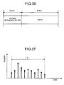
- Fig. 36 is a diagram which shows the format of a transmission slot for each sub-carrier.
- the transmission slot comprises a pilot symbol portion (known sequence) and a data portion.
- Fig. 37 is a diagram which shows one example of impulse response of a frequency selective fading transmission line.
- radio wave reflects, diffracts and scatters due to surrounding buildings and geographical features, and incoming waves (multi-path waves) through a plurality of transmission lines interfere with each other, and hence an impulse response of the frequency selective fading transmission line occurs.
- the convolutional coder 501 having received transmission data for an optional terminal generates coded data in accordance with a predetermined code rate.
- This coded data is written in the vertical direction in the interleaver 502 comprising a block, for example, having a longitudinal size of Nr (predetermined integer) and a lateral size of Nc (predetermined integer), and read out in the lateral direction. That is, the interleaver 502 outputs the rearranged signal as coded data.
- the S/P 503 having received the coded data converts the data to parallel data for the number of Nscg (predetermined integer), and outputs the converted output to the sub-carrier group modulation processing sections 510a, 510b, ..., and 510c, respectively. Since the same signal processing is performed in the first to the Nscg-th sub-carrier group modulation processing sections which perform modulation processing for each sub-carrier group, the operation of the first sub-carrier group modulation processing section 510a will be explained here, and explanation for other sub-carrier group modulation processing sections is omitted.
- the sub-carrier group modulation processing section 510a receives the first data sequence in the parallel output from the S/P 503.
- the frame creation section 511 first divides the data sequence into a unit of Ndata, and adds the known sequence (pilot symbol) at the top thereof, to thereby generate the data frame of a sub-carrier group (1).
- the copy section 512 copies the received data frame by the number of a predetermined sub-carrier number Nsub, to generate data frames for sub-carriers (1, 1) to (1, Nsub).
- the information modulation section 513 executes QPSK modulation individually with respect to the data frames by the received number of sub-carriers to thereby generate modulation signals for the sub-carriers (1, 1) to (1, Nsub).
- the frequency spreading section 514 performs frequency spreading for each terminal or for each other channel to be transmitted, using modulation signals by the received number of sub-carriers and frequency spreading codes orthogonal to each other which has been given beforehand. This frequency spreading is realized by multiplying the modulation signals of the received number of sub-carriers by a frequency spreading codes C (1, 1) to C(1, Nsub) (each code is expressed by ⁇ 1). As the frequency spreading code, Walsch code, being an orthogonal code, is normally used.
- the multiplexing section 504a generates a multiplexing signal by multiplexing similar signals by the number of sub-carriers from other users, with respect to the received signals by the number of sub-carriers after the frequency spreading.
- the inverse Fourier transform section 505 uses sub-carrier signals of the number of Nscg ⁇ Nsub obtained by the multiplexing sections 504a, 504b and 504c, to perform inverse Fourier transform processing.
- the guard interval adding section 506 copies the rear part of the symbol in the signal after inverse Fourier transform by the time ⁇ GI , and sticks the copied part to the top of the symbol.
- Fig. 38 is a diagram which shows the processing in the guard interval adding section 506.
- ⁇ GI is normally set so as to become larger than the delayed wave expanse ⁇ d on the transmission line shown in Fig. 37.
- Fig. 39 is a diagram which shows the transmission signal expressed on a frequency axis.
- the receiver receives the transmission signal affected by the frequency selective fading or the like, via the antenna 601.
- the frequency transform section 602 performs bandwidth limiting by means of a band-pass filter (not shown) with respect to the input signal, and then multiplies the signal after performing the bandwidth limiting by a signal synchronous to the carrier wave frequency output by the frequency synthesizer (not shown).
- the multiplied signal is subjected to wave filtering by a low-pass filter (not shown) so that only a low frequency component is output as a signal after frequency translation.
- the guard interval (GI) removal section 603 outputs a signal in which the guard interval is removed and each symbol is continuously connected to each other.
- the Fourier transform section 604 having received the signal in which the guard interval has been removed performs the Fourier transform processing, to thereby output sub-carrier signals by the number of Nscg ⁇ Nsub.
- Each sub-carrier signal is transmitted to the first, the second, ... , and the Nscg-th sub-carrier group modulation processing sections 610a, 610b and 610c, respectively, in order to perform demodulation processing for each sub-carrier group.
- the first, the second and the Nscg-th sub-carrier group demodulation processing sections 610a, 610b and 610c the same signal processing is performed. Therefore, only the operation of the first sub-carrier group demodulation processing section 610a will be explained herein, and explanation for the other sub-carrier group demodulation processing sections is omitted.
- the sub-carrier group demodulation processing section 610a receives the first sub-carrier signals by the number of Nsub, and the frequency despreading section 611 multiplies the sub-carrier signals by the number of Nsub by an individually allocated spreading code, to thereby perform inverse spreading.
- the synchronization detector 612 which has received each sub-carrier signal after frequency despreading uses the known sequence symbol added for each frame to estimate the transmission line to thereby perform synchronization detection. That is to say, the synchronization detector 612 synchronously adds the known sequence symbols by the number of Npilot in the frame, to thereby calculate a transmission line estimate value for each sub-carrier. The synchronization detector 612 then calculates a complex conjugate and an absolute value of the calculation results, and divides the complex conjugate by the absolute value, to thereby extract a phase component for each sub-carrier. Finally, the synchronization detector 612 multiplies the sub-carrier signal after the frequency despreading by the phase component for each sub-carrier, to perform synchronization detection.
- the combining section 613 adds all the received sub-carrier signals after the synchronization detection to calculate the first sub-carrier group signal.
- the P/S 605 receives the sub-carrier group signals from all the sub-carrier group demodulation processing sections, and converts these signals to serial signals.
- the serial signals are written in the lateral direction in the deinterleaver 606 which has blocks having a longitudinal size of Nr (predetermined integer) and a lateral size of Nc (predetermined integer), and read out in the longitudinal direction.
- the Viterbi decoder 607 performs known Viterbi decoding with respect to the received signal after rearrangement.
- the expanse of the delayed wave is large depending on the situation of the transmission line, and sometimes the expanse of the delayed wave may not be fitted in the guard interval. In such an instance, there is a problem in that the apparatus is affected by the frequency selective fading, thereby the influence of interference increases in the symbol, and an excellent bit error rate characteristic cannot be obtained.
- the delayed wave is not utilized for increasing the quality of the input signal (for example, a signal power to interference power ratio (SIR)).
- SIR signal power to interference power ratio
- the frequency spreading code is allocated for each user or for each channel to be used, it is necessary to allocate a channel depending on the information transmission rate.
- the frequency spreading codes are orthogonal to each other, and since the frequency spreading rate is fixed, there is a problem in that the information rate cannot be changed adaptively.
- transmission power control is necessary on the base station side, in order to solve a problem in that the reception quality of the mobile station must be kept constant regardless of the distance from the base station.
- the degree of influence by the frequency selective fading differs largely for each sub-carrier. Therefore, with the conventional method in which the input signal power is kept constant in the mobile station, there is a problem in that the input signal quality cannot be kept constant, while suppressing the influence with respect to other mobile stations (terminals).
- the transmitter comprises signal modulation units for the number of sub-carrier groups (corresponding to sub-carrier group processing sections 6a to 8c), which performs frequency spreading for each sub-carrier signal of each channel constituting a sub-carrier group, based on a predetermined condition, and time spread units for the number of sub-carrier groups (corresponding to multiplexing sections 9a to 9c, and time spreading sections 10a to 10c), which multiplex all the signals after the modulation processing and the frequency spreading for each sub-carrier signal, and perform time spreading with respect to the multiplexed signals for each sub-carrier signal.
- the receiver comprises time despreading units for the number of sub-carrier groups (corresponding to time despreading sections 35a to 35c), which perform time despreading for each sub-carrier signal, and signal demodulation units for the number of sub-carrier groups (corresponding to sub-carrier group demodulation processing sections 36a to 38c), which perform frequency despreading for each sub-carrier signal after the time despreading.
- the transmitter comprises a setting unit (corresponding to a data/modulation control section 4 in an embodiment described later) which sets a code rate of error correction, number of sub-carrier groups, frequency spreading rate, number of code multiplexes of a frequency spreading code, frequency spreading code, time spreading rate, number of code multiplexes of a time spreading code and time spreading code, signal modulation units for the number of sub-carrier groups (corresponding to sub-carrier group modulation processing sections 6a to 8c) which perform frequency spreading for each sub-carrier signal of each channel constituting a sub-carrier group, based on the set conditions, and time spread units for the number of sub-carrier groups (corresponding to multiplexing sections 9a to 9c, and time spreading sections 10a to 10c), which multiplex all the signals after the modulation processing and the frequency spreading for each sub-carrier signal, and perform time spreading with respect to the multiplexed signals for each sub-carrier signal.
- a setting unit corresponding to a data/modulation control section 4 in an embodiment described later
- the receiver comprises time despreading units for the number of sub-carrier groups (corresponding to time despreading sections 35a to 35c), which perform time despreading for each sub-carrier signal; and signal demodulation units for the number of sub-carrier groups (corresponding to sub-carrier group demodulation processing sections 36a to 38c), which perform frequency despreading for each sub-carrier signal after the time despreading.
- signal modulation unit comprises a frame creation unit (corresponding to a frame creation section 21) which creates data frames comprising a known sequence, frame information and data, for each sub-carrier group based on the conditions, a copy unit (corresponding to a copy section 22) which generates data frames for the number of sub-carriers, by copying the data frame, an information modulation unit (corresponding to an information modulation section 23) which performs modulation processing with respect to each data frame, a frequency spreading unit (corresponding to a frequency spreading section 24) which performs frequency spreading with respect to each sub-carrier signal after modulation, based on the conditions; and a power control unit (corresponding to a power control section 25) which performs transmission power control with respect to each sub-carrier signal after the frequency spreading.
- a frame creation unit corresponding to a frame creation section 21
- a copy unit corresponding to a copy section 22
- an information modulation unit corresponding to an information modulation section 23
- a frequency spreading unit corresponding to a frequency spreading section 24
- the setting unit sets the code rate of error correction, based on an input signal power to interference power ratio transmitted from the receiver.
- the setting unit ensures an allocatable frequency spreading code by reducing the frequency spreading rate.
- the setting unit sets the code rate of error correction, based on an input signal power to interference power ratio transmitted from the receiver.
- the setting unit ensures an allocatable frequency spreading code by reducing the frequency spreading rate.
- the setting unit ensures an allocatable frequency spreading code, by ensuring a plurality of frequency spreading codes in the same sub-carrier group.
- the setting unit allocates the frequency spreading code, by leaving a predetermined frequency interval, while keeping the orthogonality and hierarchical relationship between frequency spreading codes.
- the signal demodulation unit comprises, a frequency despreading unit (corresponding to a frequency despreading section 54) which performs frequency despreading for each sub-carrier signal; a synchronization detector (corresponding to a synchronization detector 55) which performs transmission line estimation for each sub-carrier signal after the frequency inverse conversion, based on the known sequence added to the data frame, calculates an absolute value and a complex conjugate of the transmission line estimation results, normalizes the complex conjugate by the absolute value, weights the sub-carrier signal by the normalization result, and outputs the absolute value and the sub-carrier signal after weighting as an output; a synthesizing unit (corresponding to a combining section 56) which generates a signal for the sub-carrier group by adding all the sub-carrier signals after weighting, and synthesizes an absolute value for the sub-carrier group by adding all the absolute values; and a path synthesizing unit (corresponding to a path
- the signal demodulation unit comprises, a frequency despreading unit which performs frequency despreading for each sub-carrier signal; a synchronization detector which performs transmission line estimation for each sub-carrier signal after the frequency inverse conversion, based on the known sequence added to the data frame, calculates a complex conjugate of the transmission line estimation results, weights the sub-carrier signal by the complex conjugate, and outputs the sub-carrier signal after weighting as an output; a synthesizing unit which generates a signal for the sub-carrier group by adding all the sub-carrier signals after weighting; and a path synthesizing unit which adds all the sub-carrier group signals corresponding to each path, to thereby generate a sub-carrier group signal after path combining.
- the signal demodulation unit comprises, a frequency despreading unit which performs frequency despreading in a unit of the sub-carrier signal; a synchronization detector which performs transmission line estimation for each sub-carrier signal after the frequency inverse conversion, based on the known sequence added to the data frame, calculates an absolute value and a complex conjugate of the transmission line estimation results, normalizes the complex conjugate by the absolute value, weights the sub-carrier signal by the normalization result, and on the other hand, estimates an interference power for each sub-carrier signal after the frequency inverse conversion based on the known sequence, and divides the sub-carrier signal after weighting by the interference power; a synthesizing unit which generates a signal for the sub-carrier group by adding all the sub-carrier signals after synchronization detection, and generates an absolute value for the sub-carrier group by adding all the absolute values; and a path synthesizing unit which multiplies the sub-carrier
- the signal demodulation unit comprises, a frequency despreading unit which performs frequency despreading in a unit of the sub-carrier signal; a synchronization detector which performs transmission line estimation for each sub-carrier signal after the frequency inverse conversion, based on the known sequence added to the data frame, calculates a complex conjugate of the transmission line estimation results, weights the sub-carrier signal by the complex conjugate, and lastly removes an interference component from the sub-carrier signal after weighting; a synthesizing unit which generates a signal for the sub-carrier group by adding all the sub-carrier signals after removing the interference; and a path synthesizing unit which adds all the sub-carrier group signals corresponding to each path, to thereby generate a sub-carrier group signal after the path combining.
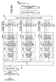
- the transmitter comprises signal modulation units (corresponding to sub-carrier group modulation processing sections 282a to 284c) for the number of sub-carrier groups, which perform frequency spreading and time spreading for each sub-carrier signal of each channel constituting a sub-carrier group, based on a predetermined condition
- the receiver comprises signal demodulation units (corresponding to sub-carrier group demodulation processing sections 301a to 303c) for the number of sub-carrier groups, which perform time despreading and frequency despreading for each sub-carrier signal.
- the transmitter comprises, a setting unit (corresponding to a data/modulation control section 281) which sets a code rate of error correction, number of sub-carrier groups, frequency spreading rate, number of code multiplexes of frequency spreading code, frequency spreading code, time spreading rate, number of code multiplexes of time spreading code and time spreading code; and signal modulation units (corresponding to sub-carrier group modulation processing sections 282a to 284c) for the number of sub-carrier groups which perform frequency spreading and time spreading for each sub-carrier signal of each channel constituting a sub-carrier group, based on the setting; and the receiver comprises signal demodulation units (corresponding to sub-carrier group demodulation processing sections 301a to 303c) for the number of sub-carrier groups, which perform time despreading and frequency despreading for each sub-carrier signal.
- a setting unit corresponding to a data/modulation control section 281 which sets a code rate of error correction, number of sub-carrier groups, frequency spreading rate, number of code multiplexe
- the signal modulation unit comprises, a frame creation unit which creates data frames comprising a known sequence, frame information and data, for each sub-carrier group based on the conditions, a copy unit which generates data frames for the number of sub-carriers, by copying the data frame, an information modulation unit which performs modulation processing with respect to the each data frame, a frequency spreading unit which performs frequency spreading with respect to each sub-carrier signal after modulation, based on the conditions, a power control unit which performs transmission power control with respect to each sub-carrier signal after the frequency spreading, and a time spread unit (corresponding to a time spreading section 291) which performs time spreading with respect to each sub-carrier signal after the frequency spreading.
- a frame creation unit which creates data frames comprising a known sequence, frame information and data, for each sub-carrier group based on the conditions
- a copy unit which generates data frames for the number of sub-carriers, by copying the data frame
- an information modulation unit which performs modulation processing with respect
- the setting unit sets the code rate of error correction, based on an input signal power to interference power ratio transmitted from the receiver, and when there is no frequency spreading code nor time spreading code to be allocated, at the time of setting the frequency spreading code and time spreading code, the setting unit ensures an allocatable frequency spreading code by reducing the frequency spreading rate.
- the setting unit sets the code rate of error correction, based on an input signal power to interference power ratio transmitted from the receiver, and when there is no frequency spreading code nor time spreading code to be allocated, at the time of setting the frequency spreading code and time spreading code, the setting unit ensures an allocatable frequency spreading code by reducing the frequency spreading rate, and even in this condition, when there is still no frequency spreading code nor time spreading code to be allocated, the setting unit ensures an allocatable frequency spreading code, by ensuring a plurality of frequency spreading codes in the same sub-carrier group.
- the setting unit sets the code rate of error correction, based on an input signal power to interference power ratio transmitted from the receiver, and when there is no frequency spreading code nor time spreading code to be allocated, at the time of setting the frequency spreading code and time spreading code, the setting unit ensures an allocatable frequency spreading code by reducing the frequency spreading rate, and even in this condition, when there is still no frequency spreading code nor time spreading code to be allocated, the setting unit ensures an allocatable frequency spreading code, by ensuring a plurality of frequency spreading codes in the same sub-carrier group, and even in this condition, when there is still no frequency spreading code nor time spreading code to be allocated, the setting unit ensures an allocatable frequency spreading code and time spreading code, by ensuring a plurality of frequency spreading codes in the same sub-carrier group, and increasing the number of multiplexes of the time spreading code.
- the setting unit sets the code rate of error correction, based on an input signal power to interference power ratio transmitted from the receiver, and when there is no frequency spreading code nor time spreading code to be allocated, at the time of setting the frequency spreading code and time spreading code, the setting unit ensures an allocatable frequency spreading code by reducing the frequency spreading rate, and even in this condition, when there is still no frequency spreading code nor time spreading code to be allocated, the setting unit ensures an allocatable frequency spreading code, by ensuring a plurality of frequency spreading codes in the same sub-carrier group, and even in this condition, when there is still no frequency spreading code nor time spreading code to be allocated, the setting unit ensures an allocatable frequency spreading code and time spreading code, by ensuring a plurality of frequency spreading codes in the same sub-carrier group, and decreasing the time spreading rate.
- the signal demodulation unit comprises, a time despreading unit (corresponding to a time despreading section 311) which performs time despreading for each sub-carrier signal; a frequency despreading unit which performs frequency despreading for each sub-carrier signal; a synchronization detector which performs transmission line estimation for each sub-carrier signal after the frequency inverse conversion, based on the known sequence added to the data frame, calculates an absolute value and a complex conjugate of the transmission line estimation results, normalizes the complex conjugate by the absolute value, weights the sub-carrier signal by the normalization result, and outputs the absolute value and the sub-carrier signal after weighting as an output; a synthesizing unit which generates a signal for the sub-carrier group by adding all the sub-carrier signals after weighting, and synthesizes an absolute value for the sub-carrier group by adding all the absolute values; and a path synthesizing unit which multiplie
- the signal demodulation unit comprises, a time despreading unit which performs time despreading for each sub-carrier signal; a frequency despreading unit which performs frequency despreading for each sub-carrier signal; a synchronization detector which performs transmission line estimation for each sub-carrier signal after the frequency inverse conversion, based on the known sequence added to the data frame, calculates a complex conjugate of the transmission line estimation results, weights the sub-carrier signal by the complex conjugate, and outputs the sub-carrier signal after weighting as an output; a synthesizing unit which generates a signal for the sub-carrier group by adding all the sub-carrier signals after weighting; and a path synthesizing unit which adds all the sub-carrier group signals corresponding to each path, to thereby generate a sub-carrier group signal after path combining.
- the signal demodulation unit comprises, a time despreading unit which performs time despreading for each sub-carrier signal; a frequency despreading unit which performs frequency despreading in a unit of the sub-carrier signal; a synchronization detector which performs transmission line estimation for each sub-carrier signal after the frequency inverse conversion, based on the known sequence added to the data frame, calculates an absolute value and a complex conjugate of the transmission line estimation results, normalizes the complex conjugate by the absolute value, weights the sub-carrier signal by the normalization result, and on the other hand, estimates an interference power for each sub-carrier signal after the frequency inverse conversion based on the known sequence, and divides the sub-carrier signal after weighting by the interference power; a synthesizing unit which generates a signal for the sub-carrier group by adding all the sub-carrier signals after synchronization detection, and generates an absolute value for the sub-carrier group by
- the signal demodulation unit comprises, a time despreading unit which performs time despreading for each sub-carrier signal; a frequency despreading unit which performs frequency despreading in a unit of the sub-carrier signal; a synchronization detector which performs transmission line estimation for each sub-carrier signal after the frequency inverse conversion, based on the known sequence added to the data frame, calculates a complex conjugate of the transmission line estimation results, weights the sub-carrier signal by the complex conjugate, and on the other hand, estimates an interference power for each sub-carrier signal after the frequency inverse conversion based on the known sequence, and divides the sub-carrier signal after weighting by the interference power; a synthesizing unit which generates a signal for the sub-carrier group by adding all the sub-carrier signals after synchronization detection; and a path synthesizing unit which adds all the sub-carrier group signals corresponding to each path, to thereby generate
- a multi-carrier CDMA transmitter comprises signal modulation units for the number of sub-carrier groups, which perform frequency spreading for each sub-carrier signal of each channel constituting a sub-carrier group, based on a predetermined condition, and time spread units for the number of sub-carrier groups, which multiplex all the signals after the modulation processing and the frequency spreading for each sub-carrier signal, and perform time spreading with respect to the multiplexed signals for each sub-carrier signal.
- a multi-carrier CDMA transmitter comprises a setting unit which sets a code rate of error correction, number of sub-carrier groups, frequency spreading rate, number of code multiplexes of frequency spreading code, frequency spreading code, time spreading rate, number of code multiplexes of time spreading code and time spreading code, signal modulation units for the number of sub-carrier groups which perform frequency spreading for each sub-carrier signal of each channel constituting a sub-carrier group, based on the set conditions, and time spread units for the number of sub-carrier groups, which multiplex all the signals after the modulation processing and the frequency spreading for each sub-carrier signal, and perform time spreading with respect to the multiplexed signals for each sub-carrier signal.
- a multi-carrier CDMA transmitter comprises signal modulation units for the number of sub-carrier groups, which perform frequency spreading and time spreading for each sub-carrier signal of each channel constituting a sub-carrier group, based on a predetermined condition.
- a multi-carrier CDMA transmitter comprises a setting unit which sets a code rate of error correction, number of sub-carrier groups, frequency spreading rate, number of code multiplexes of frequency spreading code, frequency spreading code, time spreading rate, number of code multiplexes of time spreading code and time spreading code, and signal modulation units for the number of sub-carrier groups which perform frequency spreading and time spreading for each sub-carrier signal of each channel constituting a sub-carrier group, based on the set conditions.
- a multi-carrier CDMA receiver comprises time despreading units for the number of sub-carrier groups, which perform time despreading for each sub-carrier signal, and signal demodulation units for the number of sub-carrier groups, which perform frequency despreading for each sub-carrier signal after the time despreading.
- a multi-carrier CDMA receiver comprises signal demodulation units for the number of sub-carrier groups, which perform time despreading and frequency despreading for each sub-carrier signal.
- Fig. 1 and Fig. 2 are diagrams which show the construction of a multi-carrier CDMA communication apparatus of the present invention in the first embodiment.
- Fig. 1 is a diagram which shows the construction of a multi-carrier CDMA transmitter
- Fig. 2 is a diagram which shows the construction of a multi-carrier CDMA receiver in this embodiment.
- reference symbol 1 denotes a convolutional coder
- 2 denotes an interleaver
- 3 denotes a serial/parallel conversion section (hereinafter, referred to as S/P)
- 4 denotes a data/modulation control section
- 5 denotes a power control control section
- 8a, 8b and 8c denote first, second, and Nscg-th sub-carrier group modulation processing sections provided for each channel
- 9a, 9b and 9c denote multiplexing sections
- 10a, 10b and 10c denote time spreading sections
- 11 denotes an inverse Fourier transform section
- 12 denotes a frequency transform section
- 13 denotes an antenna
- 21 denotes a frame creation section
- 22 denotes a copy section
- 23 denotes an information modulation section
- 24 denotes a frequency spreading section
- 25 denotes a power control section.
- reference symbol 31 denotes an antenna
- 32 denotes a frequency transform section
- 33 denotes a Fourier transform section
- 34 denotes a sub-carrier selection section
- 35a, 35b and 35c denote first, second, and Nscg-th sub-carrier group time despreading sections, 36a, 36b, 36c, 37a, 37b, 37c, ...
- 38a, 38b and 38c denote first, second, and Nscg-th sub-carrier group demodulation processing sections provided for each multiplex channel
- 39 denotes a parallel/serial conversion section ("P/S")
- 40 denotes an input signal quality information generation section
- 41 denotes a deinterleaver
- 42 denotes a Viterbi decoder
- 43 denotes a data/demodulation control section
- 51, 52 and 53 denote path demodulation processing sections for each path
- 54 denotes a frequency despreading section
- 55 denotes a synchronization detector
- 56 denotes a combining section
- 57 denotes a path combining section.
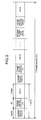
- Fig. 3 is a diagram which shows a format of a transmission slot for each sub-carrier.
- the transmission slot comprises a pilot symbol portion (known sequence), a frame information portion and a data portion.
- the convolutional coder 1 having received the transmission data with respect to an optional terminal performs convolutional coding of the transmission signal, based on a "code rate set-point signal" for setting the code rate of error correction according to the desired communication quality, which is transmitted from the data/modulation control section 4.
- the interleaver 2 rearranges the convolutional coding data.
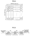
- Fig. 4 is a diagram which shows the construction of the interleaver 2.
- blocks having a longitudinal size of Nr (predetermined integer) and a lateral size of Nc (predetermined integer) and as shown in Fig. 4, the coded data is written in the longitudinal direction, and then read out in the lateral direction. As a result, the coded data is rearranged for each frame.
- the S/P 3 receives the rearranged coded data, and a "set-point signal" for setting the number of sub-carrier groups Nscg, the frequency spreading rate Nsub, and the number of code multiplexes M on the frequency axis, which is transmitted from the data/modulation control section 4.
- the number of sub-carrier groups Nscg and the frequency spreading rate Nsub take a value of not less than 1 and not larger than the number of all sub-carriers on the frequency band.
- the S/P 3 converts the rearranged coded data (serial signal) to a parallel signal corresponding to all channels in each sub-carrier group.
- the sub-carrier group modulation processing sections 6a to 8c which individually correspond to M channels for the number of code multiplexes in each sub-carrier group, receive the parallel signal and the set-point signal to thereby performmodulation processing for each channel.
- the M sub-carrier group modulation processing sections 6a to 8c in the first to the Nscg-th sub-carrier groups the same signal processing is performed.
- the operation of only the sub-carrier group modulation processing section 6a in the first channel will be explained herein, and the explanation of other sub-carrier group modulation processing sections is omitted.
- the number of sub-carrier groups Nscg and the number of code multiplexes M for each sub-carrier group are variables determined in the data/modulation control section 4.
- the sub-carrier group modulation processing section 6a receives the first data sequence in the parallel signal, to perform predetermined processing shown below.
- Fig. 5 is a diagram which shows the construction of the frame creation section 21.
- reference symbol 61 denotes a data dividing section for each slot
- 62 denotes a frame information adding section
- 63 denotes a known sequence adding section.
- the data dividing section for each slot in the frame creation section 21 divides the data sequence into units of Nslot which includes a plurality of data for one slot (number of data bit Ndata) .
- the frame information adding section 62 having received the data divided into a plurality of slots adds information necessary for demodulation, such as code rate, number of sub-carrier groups Nscg, frequency spreading rate Nsub, frequency spreading code and number of code multiplexes, to the leading part of each data as the frame information for each mobile station (terminal).
- the known sequence adding section 63 further adds a known sequence (pilot symbol) to the head of each slot, to thereby generate a data frame in which slots continues time-wise, as shown in Fig. 3. The data frame is then output to the copy section 22.
- Fig. 6 is a diagram which shows the construction of the copy section 22.
- the copy section 22 copies the received data frame by the number of sub-carriers Nsub, according to the set-point signal having the frequency spreading rate output fromthe data/modulation control section 4, to thereby generate data frames for the sub-carrier signals (1, 1) to (1, Nsub). These data frames are output to the information modulation section 23.
- Fig. 7 is a diagram which shows the construction of the information modulation section 23.
- reference symbols 71, 72 and 73 denote QPSK modulation sections.
- Each QPSK modulation section performs QPSK modulation with respect to the frame data for the received number of sub-carriers, to thereby generate modulation signals for the sub-carrier (1, 1) to the sub-carrier (1, Nsub). These modulation signals are output to the frequency spreading section 24.
- Fig. 8 is a diagram which shows the construction of the frequency spreading section 24.
- reference symbol 81 denotes a frequency spreading code generation section
- 82, 83 and 84 denote multipliers.
- the frequency spreading section 24 uses the modulation signals by the received number of sub-carriers and frequency spreading codes, to perform frequency spreading. This frequency spreading is realized by multiplying the modulation signals for the received number of sub-carriers by frequency spreading codes C(1, 1) to C(1, Nsub) (each code is represented by ⁇ 1).
- the frequency spreading code the Walsch code, being an orthogonal code, is generally used.
- a sub-carrier signal after the spread modulation is output herein to the power control section 25.
- Fig. 9 is a diagram which shows the relation between a sub-carrier and a frequency spreading code group allocated for each sub-carrier
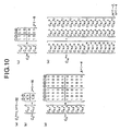
- Fig. 10 is a diagram which shows one example of construction of a frequency spreading code group.
- the number of all sub-carriers that can be used on the frequency axis is 32, and there is shown such a relation that as the number of frequency spreading codes increases, the spreading rate of the frequency spreading code decreases.
- frequency spreading codes C 1 1 , C 1 2 , ... , C 1 32 represent a frequency spreading code group which the frequency spreading rate is 1 (smallest case), and is expressed as C 1 1 , C 1 2 , ...
- Frequency spreading codes C 8 1 , C 8 2 , ... , C 8 4 represent a frequency spreading code group in which the frequency spreading rate is 8, and has eight kinds of frequency spreading codes orthogonal to each other, as shown in Fig. 10(d).
- Frequency spreading codes C 16 1 and C 16 2 represent a frequency spreading code group in which the frequency spreading rate is 16, and has 16 kinds of frequency spreading codes orthogonal to each other, as shown in Fig. 10(e).
- (C)' in Fig. 10(e) represents a complement of C.
- the code itself is expressed by Hadamard-Walsch code, which is one of the orthogonal codes.
- the generation method of the frequency spreading codes can be expressed by the following equation (1), in the case of generalization.
- Fig. 11 is a diagram which shows the situation that the frequency spreading codes are hierarchically orthogonal to each other.
- the frequency spreading code in which the orthogonal condition is concluded hierarchically is used for the frequency spreading code, thereby channel data having a plurality of frequency spreading rate can be transmitted under the specific constrained condition shown in Fig. 11.
- the frequency spreading rate is decreased, the number of sub-carrier groups increases, thereby enabling an increase in the transmission data speed.
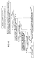
- Fig. 12 is a flowchart which shows a method of allocating the frequency spreading code in the data/modulation control section 4.
- the "input signal quality information" generated by using the input signal power to interference power ratio (SIR) is inserted in the frame to be transmitted to the base station, in order to keep the required quality of the transmission data.
- This input signal quality information is for requesting channel allocation. Therefore, the data/modulation control section 4 having received the channel allocation request for ensuring a channel for transmission data from the mobile station (step S1) allocates a code rate based on this input signal quality information (step S2). That is, the data/modulation control section 4 sets a code rate of error correction by means of the convolutional code based on the input signal quality information.
- the code rate is set small, and when the reception condition thereof is excellent, the code rate is set large.
- the data/modulation control section 4 then allocates the same number of sub-carrier groups as the reciprocal of the code rate (step S3) as the first stage. For example, when the code rate is 1/2 and the frequency spreading rate is 4, two frequency spreading codes are selected one each from two frequency spreading code groups in the eight frequency spreading code groups C 4 1 , C 4 2 , ... , C 4 8 in Fig. 9. The frequency spreading code is selected so as not to be the same as the frequency spreading code occupied by another user and another channel. At this time, when the frequency spreading code can be ensured (step S4, Yes), the data/modulation control section 4 judges that setup is possible and determines allocation of the number of sub-carrier groups, the number of code multiplexes and the frequency spreading code (step S5).
- the data/modulation control section 4 allocates the frequency spreading code, while maintaining the transmission rate of the transmission data, as the second stage, and resets the frequency spreading rate in order to increase the usable number of sub-carrier groups.
- the frequency spreading rate of one or a plurality of sub-carrier groups which is set to be 4 is changed to 2, to double the number of sub-carrier groups which can be used in the same band, thereby ensuring the allocatable frequency spreading code (step S6).
- the data/modulation control section 4 judges that setup is possible and determines allocation of the number of sub-carrier groups, the number of code multiplexes and the frequency spreading code (step S5).
- the data/modulation control section 4 allows to ensure a plurality of frequency spreading codes in the same sub-carrier group having the frequency spreading rate of 4, as the third stage, and sets a frequency spreading code for multiplexing in the same sub-carrier group (step S8).
- the data/modulation control section 4 judges that setup is possible and determines allocation of the number of sub-carrier groups, the number of code multiplexes and the frequency spreading code (step S5).
- the frequency spreading code cannot be ensured (step S9, No)
- the data/modulation control section 4 has failed in channel allocation (step S10).
- the number of code multiplexes in the first stage is set to be 1, but the number of code multiplexes may be set to be one or larger from the first stage.
- the frequency spreading code set in this manner is transmitted as the information notified to the mobile station by means of the frame information (1) to (Nslot) in Fig. 3.
- Fig. 13 is a diagram which shows the construction of the power control section 25.
- reference symbols 91, 92, ... , 93 denote multipliers.
- the power control section 25 uses these multipliers 91, 92, 93 to multiply the power control signal for each sub-carrier group transmitted from the power control control section 5 by the sub-carrier signals (1, 1) to (1, Nsub) after frequency spreading, to thereby control the amplification level of each sub-carrier signal.
- the power control control section 5 generates a power control control signal based on the input signal quality information inserted in the frame transmitted from the mobile station. The details of the generation method of input signal quality information will be explained later.
- the multiplexing section 9a multiplexes the received sub-carrier signals (1, 1) to (1, Nsub) after power control in the first channel, and the received sub-carrier signals (1, 1) to (1, Nsub) after power control in the second to the M-th channels, respectively, to thereby generate multiplexed signals with respect to the plurality of terminals. These multiplexed signals are then output to the time spreading section 10a.
- Fig. 14 is a diagram which shows the construction of the time spreading section 10a.
- reference symbol 101 denotes a time spreading code generation section
- 102, 103 and 104 denote multipliers.
- the time spreading section 10a multiplies the time spreading code identical between sub-carriers transmitted from the time spreading code generation section 101 by the multiplexed signal, using the multipliers 102, 103 and 104, respectively, to thereby perform time spreading for each sub-carrier.
- the time spreading code it is assumed that a peculiar code is allocated for each area to which the base station is going to transmit, and the one having an excellent correlation characteristic such as PN sequence is used.
- the area referred to herein is a sector generally used in communication, or a transmission beam formed at the time of transmission from the base station, which can be spatially separated.
- the inverse Fourier transform section 11 uses sub-carrier signals for the number of Nscg ⁇ Nsub, obtained in the time spreading sections 10a, 10b and 10c, to perform inverse Fourier transform processing.
- the inverse Fourier transform section 11 then outputs a signal after inverse Fourier transform to the frequency transform section 12.
- the inverse Fourier transform section 11 has the number of inputs which makes it possible to perform the inverse Fourier transform processing with respect to the total number of sub-carriers on the preset frequency band.
- Fig. 15 is a diagram which shows the construction of the frequency transform section 12.
- reference symbol 111 denotes a frequency oscillator
- 112 denotes a multiplier
- 113 denotes a band-pass filter.
- the frequency transform section 12 multiplies the signal after inverse Fourier transform by a carrier signal in the output of the frequency oscillator 111, and performs bandwidth limiting, using the band-pass filter 113, to thereby generate a transmission signal.
- the frequency transform section 12 then outputs the transmission signal onto the transmission line via the antenna 13.
- the frequency transform section 32 receives the transmission signal affected by frequency selective fading or the like, via the antenna 31.
- Fig. 16 is a diagram which shows the construction of the frequency transform section 32.
- reference symbol 121 denotes a band-pass filter
- 122 denotes a frequency synthesizer
- 123 denotes a multiplier
- 124 denotes a low-pass filter.
- the frequency transform section 32 performs bandwidth limiting by means of the band-pass filter 121 with respect to the input signal, and then multiplies the signal after bandwidth limiting by a signal synchronous to the carrier frequency output from the frequency synthesizer 122.
- the multiplied signal is output as a signal after frequency translation, with only the low frequency component being wave-filtered by the low-pass filter 124.
- the Fourier transform section 33 performs Fourier transform processing with respect to the received signal after waveform shaping, and outputs sub-carrier signals for the number of Nscg ⁇ Nsub to the sub-carrier selection section 34.
- the Fourier transform section 33 has the number of outputs which makes it possible to perform the Fourier transform processing with respect to the total number of sub-carriers on the preset frequency band.
- the sub-carrier selection section 34 selects a sub-carrier signal in a sub-carrier group to be used for demodulation from all sub-carrier signals. Selection of the sub-carrier signal is performed based on the information of the number of sub-carrier groups Nscg, the frequency spreading rate Nsub and the frequency spreading code transmitted from the data/modulation control section 4. The selection result by the sub-carrier selection section 34 is output to the time despreading sections 35a, 35b and 35c.
- Fig. 17 is a diagram which shows the construction of the time despreading sections 35a, 35b and 35c.
- reference symbol 131 denotes a time spreading code generation section
- 132, 133 and 134 denote multipliers
- 135, 136 and 137 denote integrate & dump ("I & D") sections.
- Each time despreading section provided for each sub-carrier group has the same construction and perform similar operation. Hence, only the operation of the time despreading section 35a in the first sub-carrier group will be explained herein.
- the time despreading section 35a multiplies Nsub sub-carrier signals in the first sub-carrier group by the time spreading code individually generated in the time spreading code generation section 131.
- the time spreading code takes a value of ⁇ 1.
- each I & D integrates the outputs of multipliers for each sub-carrier, respectively, by a symbol period, to thereby generate sub-carrier signals (1, 1) to (1, Nsub) after the time despreading, while clearing the integral value.
- the sub-carrier signals after the time despreading are then output to the sub-carrier group demodulation processing sections 36a to 38a for the number of M code multiplexes.
- the information indicating that the number of code multiplexes is M is transmitted from the data/demodulation control section 34.
- the sub-carrier signals (1, 1) to (1, Nsub) after the time despreading are changed to multi-path waves due to the influence of delayed waves on the transmission line.
- the demodulation processing is performed in a unit of each path demodulation processing section 51, 52, 53 for the number of P.
- the each path demodulation processing section performs the same demodulation processing, respectively.
- the frequency despreading section 54 multiplies sub-carrier signals (1, 1) to (1, Nsub) for the first path by the frequency spreading code, to thereby perform frequency despreading.
- the sub-carrier signals (1, 1) to (1, Nsub) after the frequency despreading are output to the synchronization detector 55.
- the frequency spreading code is set by the data/demodulation control section 34.
- Fig. 18 is a diagram which shows the construction of the synchronization detector 55.
- reference symbols 141, 151 and 161 denote transmission line estimation sections
- 143, 153 and 163 denote absolute value calculation sections
- 144, 154 and 164 denote analog dividers
- 145, 155 and 165 denote multipliers.
- the synchronization detector 55 receives sub-carrier signals (1, 1) to (1, Nsub) after the frequency despreading, and performs synchronization detection, using the known sequence added for each slot in the frame.
- the synchronization detector outputs the sub-carrier signals (1, 1) to (1, Nsub) after synchronization detection and the absolute value calculation result of the sub-carrier signals (1, 1) to (1, Nsub) to the combining section 56.
- the transmission line estimation sections 141, 151 and 161 synchronously adds the known sequence symbols for the number of Npilot's added for each slot in the frame, to calculate the transmission line estimate value individually. These transmission line estimation results are then output to the complex conjugate calculation sections 142, 152 and 162, and the absolute value calculation sections 143, 153 and 163, respectively. Each complex conjugate calculation section calculates the complex conjugate of the transmission line estimation result, respectively, and each absolute value calculation section calculates the absolute value of the transmission line estimation result, respectively.
- the analog dividers 144, 154 and 164 divide the individually received complex conjugate by the corresponding absolute value, to extract a phase component necessary for performing synchronization detection for each sub-carrier.
- the multipliers 145, 155 and 165 then multiply the sub-carrier signals (1, 1) to (1, Nsub) after the frequency despreading by the phase component.
- Fig. 19 is a diagram which shows the construction of the combining section 56.
- reference symbols 171 and 172 denote adders.
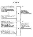
- the adder 171 adds all sub-carrier signals (1, 1) to (1, Nsub) after synchronization detection, to calculate a sub-carrier group (1) signal corresponding to the first path.
- the adder 172 adds all absolute value calculation results of each sub-carrier signal, to calculate the absolute value of the sub-carrier group (1) signal corresponding to the first path.
- the sub-carrier group (1) signal corresponding to the first path and the absolute value calculation result of the sub-carrier group (1) signal corresponding to the first path are output to the path combining section 57, together with the output of the each path demodulation processing section corresponding to other (P-1) paths.
- Fig. 20 is a diagram which shows the construction of the path combining section 57.
- reference symbols 181, 182 and 183 denote multipliers, and 184 denotes an adder .
- the path combining section 57 multiplies the sub-carrier group (1) signal corresponding to P paths by the absolute value calculation result of the sub-carrier group (1) signal corresponding to the first path.
- the adder 184 then adds P multiplication results, and outputs the sub-carrier group (1) signal after path combining.
- the output of the path combining section 57 becomes the output of the sub-carrier group demodulation processing section 36a corresponding to the first channel in the first sub-carrier group, and is output to the P/S 39 together with the outputs of the sub-carrier group demodulation processing sections 37a and 38a corresponding to the other second to M-th channels in the first sub-carrier group.
- the outputs of the sub-carrier group demodulation processing sections corresponding to the second to the M-th channels in the second to the Nscg-th sub-carrier groups are output to the P/S 39.
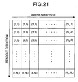
- the P/S 39 receives the sub-carrier group signals from all the sub-carrier group demodulation processing sections, and converts these signals to serial signals. Thereafter, these serial signals are written in the lateral direction in the deinterleaver 41 having blocks with a longitudinal size of Nr (where Nr is a predetermined integer) and a lateral size of Nc (where Nc is a predetermined integer), and read out in the longitudinal direction, as shown in Fig. 21.
- the Viterbi decoder 42 performs known Viterbi decoding with respect to the received rearranged signal, based on the set-point signal having a code rate transmitted from the data/demodulation control section 43.
- the output of the P/S 39 is input to the data/demodulation control section 43, and the data/demodulation control section 43 judges the frame information portion in Fig. 3 from the output of the P/S 39 to thereby obtain the frame information.
- the data/demodulation control section 43 then extracts, from the frame information, the code rate necessary for decoding control, the number of sub-carrier groups Nscg, the frequency spreading rate Nsub, the frequency spreading code and the number of code multiplexes on the frequency axis as the information.
- This information is output as the information for setting the sub-carrier selection section 34, the first, the second to the Nscg-th sub-carrier group demodulation processing sections 36a to 38a and the Viterbi decoder 42.
- the input signal quality information generation section 40 extracts a signal corresponding to the known sequence portion in the frame in the sub-carrier signal, from each of the P path demodulation processing sections in all the sub-carrier group demodulation processing sections. Further, the input signal quality information generation section 40 calculates an input signal power to interference power ratio (SIR) for each sub-carrier, using the signal of the known sequence portion. The obtained input signal power to interference power ratio is synthesized for each sub-carrier group and between all channels, paths and sub-carriers.
- SIR input signal power to interference power ratio
- the SIR for each sub-carrier group is compared with the target SIR set as a reference value which can maintain the input signal quality, based on the frame information (1) to (Nslot) from the base station, respectively.
- the SIR for each sub-carrier group is larger than the target SIR, it is judged as "1"
- the SIR for each sub-carrier group is smaller than the target SIR, it is judged as "0”.
- This judgment result is inserted in the transmission frame to be transmitted from the mobile station to the base station, so as to be notified to the base station, and be used for generating a power control control signal in the power control control section 5.
- the transmission signal from the base station is affected by frequency selective fading on the transmission line, and the expanse of the delayed wave is large, spreading in the time direction is effected by allocating a spreading code, together with spreading in the frequency direction. Further, path diversity in which paths are separated by using the path cracking ability of the delayed wave to effectively utilize the delayed wave is used. Therefore, the input signal quality (input signal power to interference power ratio (SIR)) can be increased. Further, influence of interference in the symbol can be suppressed, and excellent bit error rate characteristic can be obtained.
- SIR input signal power to interference power ratio
- path combining is performed according to the signal level of the sub-carrier signal in the sub-carrier group. Therefore, path diversity combining according to the input signal quality of each sub-carrier signal can be performed.
- Channels are allocated according to the information transmission speed and code rate, the number of sub-carrier groups and the number of sub-carriers in the sub-carrier group are made variable depending on the information transmission speed, and the frequency spreading code is hierarchically allocated for each sub-carrier group. Therefore, the frequency spreading rate is made variable, while maintaining the state that the frequency spreading code allocated for each user or for each channel to be used is orthogonal to each other. Thereby, the frequency efficiency can be increased.
- spreading is performed both in the frequency direction and the time direction, and spreading codes different in sectors or cells can be used.
- soft hand-over can be executed between sectors or cells, without interrupting the communication and without changing the frequency used on the transmission line.
- the transmission power control information inserted in the frame is used to control the transmission signal power on the base station side, so that the input signal quality becomes the same in each sub-carrier group.
- the input signal quality can be kept constant in each sub-carrier group, while reducing the interference quantity.
- a multi-carrier CDMA communication apparatus in the second embodiment has the same construction as that in the first embodiment, with the exception that the relation between the sub-carrier and the frequency spreading code arranged on the frequency axis is different. Only the portion different from that of the first embodiment will be explained herein.
- Fig. 22 is a diagram which shows the relation between a sub-carrier and a frequency spreading code group allocated for each sub-carrier.
- the frequency spreading code is allocated, with a certain frequency interval (sub-carrier interval), while keeping the orthogonality and hierarchical relationship between the frequency spreading codes.
- Sequence elements shown in Fig. 10 are periodically allocated, while keeping the orthogonality and hierarchical relationship between the frequency spreading codes shown in Fig. 9.
- the same effects as those of the first embodiment can be obtained, and further, since the frequency spreading code is allocated, with a certain frequency interval (sub-carrier interval), even if the sub-carrier signal power drops due to the frequency selective fading, a drop of the signal power in each sub-carrier group can be suppressed, thereby enabling an increase of the frequency diversity effect.
- the frequency interval is made constant, but the present invention is not limited thereto.
- two different time intervals may be used alternately, or three different time intervals may be used in an order determined beforehand.
- a multi-carrier CDMA communication apparatus in the third embodiment has the same construction as that of the first embodiment, with the exception that the internal construction and the operation of the synchronization detector 55, the combining section 56 and the path combining section 57 of the receiver are different. Only the portion different from that of the first embodiment will be explained herein.
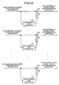
- Fig. 23 is a diagram which shows the construction of the synchronization detector 55 in the third embodiment.
- reference symbols 191, 194 and 197 denote transmission line estimation sections
- 192, 195 and 198 denote complex conjugate calculation sections
- 193, 196 and 199 denote multipliers.
- the synchronization detector 55 receives sub-carrier signals (1, 1) to (1, Nsub) after the inverse spreading, and performs synchronization detection, using the known sequence added for each slot in the frame.
- the synchronization detector 55 outputs the sub-carriersignals (1, 1) to (1, Nsub) after synchronization detection to the combining section 56.
- the transmission line estimation sections 191, 194 and 197 synchronously adds the known sequence symbols for the number of Npilot's added for each slot in the frame, to calculate the transmission line estimate value individually. These transmission line estimation results are then output to the complex conjugate calculation sections 192, 195 and 198, respectively. Each complex conjugate calculation section calculates the complex conjugate of the transmission line estimation result, respectively.
- the multipliers 193, 196 and 199 then multiply the sub-carrier signals (1, 1) to (1, Nsub) after the frequency despreading by the complex conjugate. This multiplication result is herein output to the combining section 56 as the sub-carrier signal output of the synchronization detector 55.
- Fig. 24 is a diagram which shows the construction of the combining section 56 in the third embodiment.
- reference symbol 201 denotes an adder.
- the adder 201 adds all sub-carrier signals (1, 1) to (1, Nsub) after synchronization detection, tocalculate a sub-carrier group (1) signal corresponding to the first path. Thereafter, the sub-carrier group (1) signal corresponding to the first path is output to the path combining section 57, together with the output of the each path demodulation processing section corresponding to other (P - 1) paths.
- Fig. 25 is a diagram which shows the construction of the path combining section 57 in the third embodiment.
- reference symbol 211 denotes an adder.
- the adder 211 adds the sub-carrier group (1) signals corresponding to P paths and outputs the sub-carrier group (1) signal after path combining.
- the output of the path combining section 57 becomes the output of the sub-carrier group demodulation processing section 36a corresponding to the first channel in the first sub-carrier group, and is output to the P/S 39 together with the outputs of the sub-carrier group demodulation processing sections 37a and 38a corresponding to the other second to M-th channels in the first sub-carrier group.
- the outputs of the sub-carrier group demodulation processing sections corresponding to the second to the M-th channels in the second to the Nscg-th sub-carrier groups are output to the P/S 39.
- the same effects as those of the first embodiment can be obtained, and further, since the synthesizing processing of the sub-carrier signals in the sub-carrier group and the path combining are performed, after performing the synchronization detection based on the transmission line estimate value estimated by the known pilot sequence for each sub-carrier signal, path diversity combining corresponding to the input signal quality of each sub-carrier signal can be performed.
- a multi-carrier CDMA communication apparatus in the fourth embodiment has the same construction as that of the first embodiment, with the exception that the internal construction and the operation of the synchronization detector 55 of the receiver are different. Only the portion different from that of the first embodiment will be explained herein.
- Fig. 26 is a diagram which shows the construction of the synchronization detector 55 in the fourth embodiment.
- reference symbols 221, 231 and 241 denote interference quantity estimation sections, and 222, 232 and 242 denote analog dividers.
- the synchronization detector 55 receives sub-carrier signals (1, 1) to (1, Nsub) after the inverse spreading, and performs synchronization detection, using the known sequence added for each slot in the frame.
- the synchronization detector outputs the sub-carrier signals (1, 1) to (1, Nsub) after synchronization detection, and the absolute value calculation result of the sub-carrier signals (1, 1) to (1, Nsub) to the combining section 56.
- the transmission line estimation sections 141, 151 and 161 synchronously adds the known sequence symbols for the number of Npilot's added for each slot in the frame, for each sub-carrier signal (1, 1) to (1, Nsub), to calculate the transmission line estimate value individually.
- the interference quantity estimation sections 221, 231 and 241 observe the known sequence symbols through several symbols or several slots, using the Npilot known sequence symbols added for each slot in the frame of the sub-carrier signals (1, 1) to (1, Nsub) after the frequency despreading, and calculates a distribution value to thereby calculate an interference power value.
- Each complex conjugate calculation section calculates the complex conjugate of the transmission line estimation result, respectively, and each absolute value calculation section calculates the absolute value of the transmission line estimation result, respectively.
- the analog dividers 144, 154 and 164 divide the individually received complex conjugate by the corresponding absolute value, to extract a phase component necessary for performing synchronization detection for each sub-carrier.
- the multipliers 145, 155 and 165 then multiply the sub-carrier signals (1, 1) to (1, Nsub) after the frequency despreading by the phase component.
- analog dividers 222, 232 and 242 divide the outputs of the multipliers 145, 155 and 165 by the previously calculated interference power value, respectively.
- the same effects as those of the first embodiment can be obtained, and further, since the synthesizing processing and the path combining are performed, based on the signal level and the interference quantity of the sub-carrier signal in the sub-carrier group, after performing the synchronization detection based on the transmission line estimate value estimated by the known pilot sequence for each sub-carrier signal, path diversity combining according to the input signal quality of each sub-carrier signal can be performed.
- a multi-carrier CDMA communication apparatus in the fifth embodiment has the same construction as that of the first embodiment, with the exception that the internal construction and the operation of the synchronization detector 55 of the receiver are different. Only the portion different from that of the first embodiment will be explained herein.
- Fig. 27 is a diagram which shows the construction of the synchronization detector 55 in the fifth embodiment.
- reference symbols 251, 261 and 271 denote interference quantity estimation sections, and 252, 262 and 272 denote analog dividers.
- the synchronization detector 55 receives sub-carrier signals (1, 1) to (1, Nsub) after the inverse spreading, and performs synchronization detection, using the known sequence added for each slot in the frame.
- the synchronization detector outputs the sub-carrier signals (1, 1) to (1, Nsub) after synchronization detection to the combining section 56.
- the transmission line estimation sections 191, 194 and 197 synchronously adds the known sequence symbols for the number of Npilot's added for each slot in the frame, for each sub-carrier signal (1, 1) to (1, Nsub), to calculate the transmission line estimate value individually.
- the interference quantity estimation sections 251, 261 and 271 observe the known sequence symbols through several symbols or several slots, using the Npilot known sequence symbols added for each slot in the frame of the sub-carrier signals (1, 1) to (1, Nsub) after the frequency despreading, and calculates a distribution value to thereby calculate an interference power value.
- Each complex conjugate calculation section calculates the complex conjugate of the transmission line estimation result, respectively.
- the multipliers 193, 196 and 199 then multiply the sub-carrier signals (1, 1) to (1, Nsub) after the frequency despreading by the complex conjugate.
- analog dividers 252, 262 and 272 divide the outputs of the multipliers 193, 196 and 199 by the previously calculated interference power value, respectively.
- the same effects as those of the first embodiment can be obtained, and further, since the synthesizing processing and the path combining are performed, based on the signal level and the interference quantity of the sub-carrier signal in the sub-carrier group, after performing the synchronization detection based on the transmission line estimate value estimated by the known pilot sequence for each sub-carrier signal, path diversity combining according to the input signal quality of each sub-carrier signal can be performed.
- a multi-carrier CDMA communication apparatus in the sixth embodiment has the same construction as that of the first embodiment, with the exception that a time spreading section is provided in the sub-carrier group modulation processing section prior to the multiplexing sections 9a to 9c in the transmitter, and that a time despreading section is provided in the sub-carrier group demodulation processing section provided for each channel in the receiver. Only the portion different from that of the first embodiment will be explained herein.
- Fig. 28 is a diagram which shows the construction of the transmitter in the sixth embodiment.
- reference symbol 281 denotes a data/modulation control section
- 282a, 282b, 282c, 283a, 283b, 283c, 284a, 284b and 284c denote first, second, and the Nscg-th sub-carrier group modulation processing sections provided for each channel, and 291 denote time spreading sections.
- Fig. 29 is a diagram which shows the construction of the receiver in the sixth embodiment.
- reference symbols 301a, 301b, 301c, 302a, 302b, 302c, 303a, 303b and 303c denote first, second, and the Nscg-th sub-carrier group demodulation processing sections provided for each channel, 311 denote time despreading sections, and 312 denotes a data/demodulation control section.
- the transmitter and the receiver in the sixth embodiment will be explained in detail, with reference to Fig. 28 and Fig. 29.
- the operation of the transmitter will be explained first.
- Fig. 30 is a diagram which shows the construction of the time spreading section 291 in the sixth embodiment.
- reference symbol 321 denotes a first time spreading code generation section
- 322, 323 and 324 denote multipliers
- 325 denotes a second time spreading code generation section
- 326, 327 and 328 denote multipliers.
- the time spreading section 291 multiplies the time spreading codes identical between sub-carriers transmitted from the first time spreading code generation section 321 by the sub-carrier signals (1, 1) to (1, Nsub) after power control, using the multipliers 322, 323 and 324, respectively, to thereby perform time spreading for each sub-carrier.
- the first time spreading code a peculiar code is allocated for each area to which the base station is going to transmit, and the one having an excellent correlation characteristic, such as PN sequence, is used.
- the time spreading section 291 further multiplies the time spreading codes identical between sub-carriers and orthogonal to each other for each channel in the sub-carrier group, transmitted from the second time spreading code generation section 325 by the output of sub-carrier signals of the multipliers 322, 323 and 324, respectively, to thereby perform time spreading for each sub-carrier.
- the second time spreading code for example, Hadamard-Walsch code, being one of the orthogonal codes having excellent orthogonality, used as the frequency spreading code in the first embodiment, is used.
- Fig. 31 is a flowchart which shows a method of allocating a frequency spreading code and a second time spreading code in the data/modulation control section 281.
- the mobile station inserts the "input signal quality information" generated by using the input signal power to interference power ratio (SIR) at the time of reception, into the frame to be transmitted to the base station. Therefore, the data/modulation control section 281 having received the channel allocation request for ensuring a channel for transmission data (step S21) allocates a code rate based on this input signal quality information (step S22). That is to say, the data/modulation control section 281 sets a code rate of error correction by means of a convolutional code, based on the input signal quality information. When the reception condition of the mobile station is poor based on the input signal quality information, the code rate is set small, and when the reception condition thereof is excellent, the code rate is set large.
- SIR input signal power to interference power ratio
- the data/modulation control section 281 then allocates the same number of sub-carrier groups as the reciprocal of the code rate (step S23) as the first stage.
- the frequency spreading code and the second time spreading code are selected so as not be the same as the frequency spreading code occupied by the other user and other channel.
- the data/modulation control section 281 judges that setup is possible and determines allocation of the number of sub-carrier groups, the number of code multiplexes of the frequency spreading code and the second time spreading code, and the frequency spreading code and the second time spreading code (step S25).
- the data/modulation control section 281 allocates the frequency spreading code, while maintaining the transmission rate of the transmission data, as the second stage, and resets the frequency spreading rate in order to increase the usable number offer spreading codes.
- the frequency spreading rate is decreased to increase the number of sub-carrier groups which can be used in the same band, thereby ensuring the allocatable frequency spreading code (step S26).
- the data/modulation control section 281 judges that setup is possible and determines allocation of the number of sub-carrier groups, the number of code multiplexes of the frequency spreading code and the second time spreading code, and the frequency spreading code and the second time spreading code (step S25).
- the data/modulation control section 281 allows to ensure a plurality of frequency spreading codes in the same sub-carrier group, as the third stage, and resets the frequency spreading code for multiplexing in the same sub-carrier group (step S28).
- the data/modulation control section 281 judges that setup is possible and determines allocation of the number of sub-carrier groups, the number of code multiplexes of the frequency spreading code and the second time spreading code, and the frequency spreading code and the second time spreading code (step S25).
- step S30 the data/modulation control section 281 ensures a plurality of frequency spreading codes in the same sub-carrier group as the fourth stage, and further increases the number of multiplexes of the time spreading codes for multiplexing on the time axis (step S30).
- step S31, Yes the data/modulation control section 281 judges that setup is possible and determines allocation of the number of sub-carrier groups, the number of code multiplexes of the frequency spreading code and the second time spreading code, and the frequency spreading code and the second time spreading code (step S25).
- step S31, No the data/modulation control section 281 has failed in channel allocation (step S32).
- the frequency spreading code and the second time spreading code set in this manner are transmitted as the information to be notified to the mobile station, by the frame information (1) to (Nslot) in Fig. 3, in the same manner as in the first embodiment.
- Fig. 32 is a diagram which shows the construction of the time despreading section 291 in the sixth embodiment.
- reference symbol 331 denotes a second time spreading code generation section
- 332, 333, 334, 336, 337 and 338 denote multipliers
- 335 denotes a first time spreading code generation section
- 339, 340 and 341 denote I & D's.
- the time despreading section 291 multiplies each sub-carrier signal by the second time spreading code individually generated in the second time spreading code generation section 331, based on the second time spreading code information transmitted from the data/demodulation control section 312.
- the time despreading section 291 then multiplies the outputs from the multipliers 332, 333 and 334 by the first time spreading code individually generated in the first time spreading code generation section 335, based on the first time spreading code information transmitted from the data/demodulation control section 312. After multiplication, each I & D integrates the output of the multiplier in each sub-carrier by a symbol period, respectively, to thereby generate sub-carrier signals (1, 1) to (1, Nsub) after time despreading, while clearing the integral value.
- time spreading is performed by the time spreading section 291 after the transmission power control by means of the power control section 25.
- the transmission power control may be performed by the power control section 25 after the time spreading by the time spreading section 291.
- the same effects as those of the first to the fifth embodiments can be obtained, and further, since the frequency spreading code and the time spreading code are allocated for each user or each channel to be used, the channel capacity can be increased, and as a result the frequency efficiency can be increased.
- a multi-carrier CDMA communication apparatus in the seventh embodiment has the same construction as that of the sixth embodiment, with the exception that the method of allocating the frequency spreading code and the second time spreading code is different. Only the portion different from the first embodiment and the sixth embodiment will be explained.
- Fig. 33 is a flowchart which shows the method of allocating the frequency spreading code and the second time spreading code.
- the number of code multiplexes of the second time spreading code is increased.
- the number of code multiplexes of the second time spreading code is not increased.
- the symbol speed of the data symbol is doubled, to thereby reduce the time spreading rate of the second time spreading code to 1/2, so that the signal band of the sub-carrier signal is not changed, and the orthogonality of the different time spreading codes in the same sub-carrier group does not collapse (step S41).
- the same effects as those of the first to the fifth embodiments can be obtained, and further, since the frequency spreading code and the time spreading code can be allocated for each user or each channel to be used, without increasing the number of code multiplexes of the time spreading code, the channel capacity can be increased, and as a result, the frequency efficiency can be increased.
- the present invention even if the transmission signal from the base station is affected by frequency selective fading on the transmission line, and the expanse of the delayed wave is large, spreading in the time direction is effected by allocating a spreading code, together with spreading in the frequency direction. Further, paths are separated by using the path cracking ability of the delayed wave, and path diversity which effectively utilizes the delayed wave is used. Therefore, the input signal quality can be increased. As a result, there is the effect that a multi-carrier CDMA communication apparatus, which can suppress the influence of interference in the symbol, and realize excellent bit error rate characteristic, can be obtained. Further, according to the present invention, spreading is performed both in the frequency direction and the time direction, at the time of reception, and time spreading codes different in sectors or cells can be used. As a result, there is the effect that a multi-carrier CDMA communication apparatus, which can execute soft hand-over, without interrupting the communication and without changing the frequency used on the transmission line, can be obtained.
- the transmission power control information inserted in the frame is used to control the transmission signal power on the base station side, so that the input signal quality becomes the same in each sub-carrier group.
- the input signal quality can be kept constant in each sub-carrier group, while reducing the interference quantity.
- channels are allocated according to the information transmission speed and code rate, and the frequency spreading code is hierarchically allocated for each sub-carrier group. Therefore, the frequency spreading rate can be made variable, while maintaining the state that the frequency spreading code allocated for each user or for each channel to be used is orthogonal to each other. Thereby, there is the effect that the frequency efficiency can be increased.
- the frequency spreading code is allocated, with a predetermined frequency interval, even if the sub-carrier signal power drops due to frequency selective fading, a decrease in the signal power for each sub-carrier group can be suppressed. As a result, there is the effect that the frequency diversity effect can be increased.
- the path combining is performed according to the signal level of the sub-carrier signal in the sub-carrier group.
- the synthesizing processing of the sub-carrier signals in the sub-carrier group and the path combining are performed, after performing the synchronization detection based on the transmission line estimate value estimated by the known pilot sequence for each sub-carrier signal, there is the effect that path diversity combining according to the input signal quality of each sub-carrier signal can be performed.
- the synthesizing processing and the path combining are performed, based on the signal level and the interference quantity of the sub-carrier signal in the sub-carrier group, after performing the synchronization detection based on the transmission line estimate value estimated by the known pilot sequence for each sub-carrier signal, there is the effect that path diversity combining according to the input signal quality of each sub-carrier signal can be performed.
- the synthesizing processing and the path combining are performed, based on the signal level and the interference quantity of the sub-carrier signal in the sub-carrier group, after performing the synchronization detection based on the transmission line estimate value estimated by the knownpilot sequence for each sub-carrier signal, there is the effect that path diversity combining according to the input signal quality of each sub-carrier signal can be performed.
- the transmission signal from the base station is affected by frequency selective fading on the transmission line, and the expanse of the delayed wave is large, spreading in the time direction is effected by allocating a spreading code, together with spreading in the frequency direction. Further, paths are separated by using the path cracking ability of the delayed wave, and path diversity which effectively utilizes the delayed wave is used. Therefore, the input signal quality can be increased. As a result, there is the effect that a multi-carrier CDMA communication apparatus, which can suppress the influence of interference in the symbol, and realize excellent bit error rate characteristic, can be obtained. Further, according to the present invention, spreading is performed both in the frequency direction and the time direction, at the time of reception, and time spreading codes different in sectors or cells can be used. As a result, there is the effect that a multi-carrier CDMA communication apparatus, which can execute soft hand-over, without interrupting the communication and without changing the frequency used on the transmission line, can be obtained.
- the transmission power control information inserted in the frame is used to control the transmission signal power on the base station side, so that the input signal quality becomes the same in each sub-carrier group.
- the input signal quality can be kept constant in each sub-carrier group, while reducing the interference quantity.
- the channel capacity can be increased, and as a result, there is the effect that the frequency efficiency can be increased.
- the frequency spreading code and the time spreading code are allocated for each user or each channel to be used, without increasing the number of code multiplexes of the time spreading code, the channel capacity can be increased, and as a result, there is the effect that the frequency efficiency can be increased.
- the path combining is performed according to the signal level of the sub-carrier signal in the sub-carrier group.
- the synthesizing processing of the sub-carrier signals in the sub-carrier group and the path combining are performed, after performing the synchronization detection based on the transmission line estimate value estimated by the known pilot sequence for each sub-carrier signal, there is the effect that path diversity combining according to the input signal quality of each sub-carrier signal can be performed.
- the synthesizing processing and the path combining are performed, based on the signal level and the interference quantity of the sub-carrier signal in the sub-carrier group, after performing the synchronization detection based on the transmission line estimate value estimated by the known pilot sequence for each sub-carrier signal, there is the effect that path diversity combining according to the input signal quality of each sub-carrier signal can be performed.
- the synthesizing processing and the path combining are performed, based on the signal level and the interference quantity of the sub-carrier signal in the sub-carrier group, after performing the synchronization detection based on the transmission line estimate value estimated by the knownpilot sequence for each sub-carrier signal, there is the effect that path diversity combining according to the input signal quality of each sub-carrier signal can be performed.
- the signal modulation unit allocates a spreading code in the frequency direction to effect spreading
- the time spread unit allocates a spreading code in the time direction to effect spreading.
- the signal modulation unit allocates a spreading code in the frequency direction to effect spreading, together with spreading in the frequency direction.
- the time despreading unit performs inverse spreading in the time direction
- the signal demodulation unit performs inverse spreading in the frequency direction
- path diversity in which paths are separated by using the path cracking ability of the delayed wave to effectively utilize the delayed wave is used.
- the signal demodulation unit performs inverse spreading in the time direction and inverse spreading in the frequency direction, and path diversity in which paths are separated by using the path cracking ability of the delayed wave to effectively utilize the delayed wave is used.
- the multi-carrier CDMA communication apparatus, the multi-carrier CDMA transmitter and the multi-carrier CDMA receiver according to the present invention are suitable for mobile communication system which adopts a multiple access scheme using the multi-carrier CDMA method, and are useful for obtaining excellent bit error rate characteristic, even in a communication environment affected by frequency selective fading.
Landscapes
- Engineering & Computer Science (AREA)
- Signal Processing (AREA)
- Computer Networks & Wireless Communication (AREA)
- Mobile Radio Communication Systems (AREA)
- Digital Transmission Methods That Use Modulated Carrier Waves (AREA)
Abstract
The transmitter comprises a data/modulation control
section (4) which sets predetermined parameters necessary
for demodulation processing, sub-carrier group modulation
processing sections (6a to 8c) which perform frequency
spreading for each sub-carrier signal in the sub-carrier
group, and time spreading sections (10a to 10c) which
multiplex all signals after the modulation processing and
the frequency spreading for each sub-carrier signal, and
perform time spreading with respect to the multiplexed
signals. The receiver comprises time despreading sections
(35a to 35c) which perform time despreading for each
sub-carrier signal, and sub-carrier group demodulation
processing sections (36a to 38c) which perform frequency
despreading for each sub-carrier signal after the time
despreading.
Description
The present invention relates to a communication
apparatus in a mobile communication system which adopts a
multiple access scheme, using a multi-carrier CDMA method.
More particularly, the present invention relates to a
multi-carrier CDMA communication apparatus, a
multi-carrier CDMA transmitting apparatus and a
multi-carrier CDMA receiving apparatus, which can obtain
excellent bit error rate characteristic even in a
communication environment affected by frequency selective
fading.
A conventional multi-carrier CDMA communication
apparatus will now be explained. As a communication
apparatus in a mobile communication system which adopts the
multiple access scheme, using the multi-carrier CDMA method,
there can be mentioned for example the one described in the
literatures "Performance comparisons of coherent
SC/DS-CDMA, MC/DS-CDMA, MC-CDMA on down-link broadband
radio packet transmission", The Institute of Electronics,
Information and Communication Engineers, Technical Report
IEICE RCS99-130 p.63-70, Oct. 1999, and "Overview of
Multi-carrier CDMA", IEEE Communications Magazine, p.
126-133, Dec. 1997.
The construction and operation of the conventional
multi-carrier CDMA communication apparatus will now be
explained with reference to the drawings. Fig. 34 is a
diagram which shows the construction of a conventional
multi-carrier CDMA transmitting apparatus
("transmitter"), and Fig. 35 is a diagram which shows the
construction of a conventional multi-carrier CDMA receiving
apparatus ("receiver").
In Fig. 34, reference symbol 501 denotes a
convolutional coder, 502 denotes an interleaver, 503 denotes
a serial/parallel conversion section (hereinafter,
referred to as S/P), 510a, 510b and 510c respectively denote
first, second, and the Nscg-th sub-carrier group modulation
processing sections, 511 denotes a frame creation section,
512 denotes a copy section, 513 denotes an information
modulation section, 514 denotes a frequency spreading
section, 504a, 504b and 504c denote multiplexing sections,
505 denotes an inverse Fourier transform section, 506 denotes
a guard interval (GI) adding section, 507 denotes a frequency
transform section and 508 denotes an antenna.
On the other hand, in Fig. 35, reference symbol 601
denotes a frequency transform section, 602 denotes a
frequency transform section, 603 denotes a guard interval
(GI) removal section, 604 denotes a Fourier transform section,
610a, 610b and 610c respectively denote first, second, and
the Nscg-th sub-carrier group demodulation processing
sections, 611 denotes a frequency despreading section, 612
is a synchronization detector, 613 denotes a combining
section, 605 denotes a parallel/serial conversion section
(hereinafter referred to as P/S), 606 denotes a
deinterleaver, and 607 denotes a Viterbi decoder.
Fig. 36 is a diagram which shows the format of a
transmission slot for each sub-carrier. The transmission
slot comprises a pilot symbol portion (known sequence) and
a data portion.
Fig. 37 is a diagram which shows one example of impulse
response of a frequency selective fading transmission line.
For example, in the mobile communication system, radio wave
reflects, diffracts and scatters due to surrounding
buildings and geographical features, and incoming waves
(multi-path waves) through a plurality of transmission lines
interfere with each other, and hence an impulse response
of the frequency selective fading transmission line occurs.
The operation of the conventional multi-carrier CDMA
communication apparatus will be explained with reference
to Fig. 34 and Fig. 35. It is assumed here that data transfer
is performed between a base station and a plurality of
terminals. At first, the operation of the transmitter will
be explained.
For example, the convolutional coder 501 having
received transmission data for an optional terminal
generates coded data in accordance with a predetermined code
rate. This coded data is written in the vertical direction
in the interleaver 502 comprising a block, for example,
having a longitudinal size of Nr (predetermined integer)
and a lateral size of Nc (predetermined integer), and read
out in the lateral direction. That is, the interleaver 502
outputs the rearranged signal as coded data.
The S/P 503 having received the coded data converts
the data to parallel data for the number of Nscg
(predetermined integer), and outputs the converted output
to the sub-carrier group modulation processing sections 510a,
510b, ..., and 510c, respectively. Since the same signal
processing is performed in the first to the Nscg-th
sub-carrier group modulation processing sections which
perform modulation processing for each sub-carrier group,
the operation of the first sub-carrier group modulation
processing section 510a will be explained here, and
explanation for other sub-carrier group modulation
processing sections is omitted.
The sub-carrier group modulation processing section
510a receives the first data sequence in the parallel output
from the S/P 503. The frame creation section 511 first
divides the data sequence into a unit of Ndata, and adds
the known sequence (pilot symbol) at the top thereof, to
thereby generate the data frame of a sub-carrier group (1).
The copy section 512 copies the received data frame by the
number of a predetermined sub-carrier number Nsub, to
generate data frames for sub-carriers (1, 1) to (1, Nsub).
The information modulation section 513 executes QPSK
modulation individually with respect to the data frames by
the received number of sub-carriers to thereby generate
modulation signals for the sub-carriers (1, 1) to (1, Nsub).
The frequency spreading section 514 performs frequency
spreading for each terminal or for each other channel to
be transmitted, using modulation signals by the received
number of sub-carriers and frequency spreading codes
orthogonal to each other which has been given beforehand.
This frequency spreading is realized by multiplying the
modulation signals of the received number of sub-carriers
by a frequency spreading codes C (1, 1) to C(1, Nsub) (each
code is expressed by ±1). As the frequency spreading code,
Walsch code, being an orthogonal code, is normally used.
The multiplexing section 504a generates a multiplexing
signal by multiplexing similar signals by the number of
sub-carriers from other users, with respect to the received
signals by the number of sub-carriers after the frequency
spreading.
The inverse Fourier transform section 505 uses
sub-carrier signals of the number of Nscg × Nsub obtained
by the multiplexing sections 504a, 504b and 504c, to perform
inverse Fourier transform processing.
The guard interval adding section 506 copies the rear
part of the symbol in the signal after inverse Fourier
transform by the time τGI, and sticks the copied part to the
top of the symbol. Fig. 38 is a diagram which shows the
processing in the guard interval adding section 506. τGI
is normally set so as to become larger than the delayed wave
expanse τd on the transmission line shown in Fig. 37.
Finally, the frequency transform section 507
multiplies the signal after adding the guard interval by
a carrier wave signal in the output of a frequency oscillator
(not shown), and executes bandwidth limiting, using a
band-pass filter (not shown), to thereby generate a
transmission signal. The transmission signal is then
output to the transmission line via the antenna 508. Fig.
39 is a diagram which shows the transmission signal expressed
on a frequency axis.
On the other hand, the receiver receives the
transmission signal affected by the frequency selective
fading or the like, via the antenna 601. The frequency
transform section 602 performs bandwidth limiting by means
of a band-pass filter (not shown) with respect to the input
signal, and then multiplies the signal after performing the
bandwidth limiting by a signal synchronous to the carrier
wave frequency output by the frequency synthesizer (not
shown). The multiplied signal is subjected to wave
filtering by a low-pass filter (not shown) so that only a
low frequency component is output as a signal after frequency
translation.
The guard interval (GI) removal section 603 outputs
a signal in which the guard interval is removed and each
symbol is continuously connected to each other. The Fourier
transform section 604 having received the signal in which
the guard interval has been removed performs the Fourier
transform processing, to thereby output sub-carrier signals
by the number of Nscg × Nsub. Each sub-carrier signal is
transmitted to the first, the second, ... , and the Nscg-th
sub-carrier group modulation processing sections 610a, 610b
and 610c, respectively, in order to perform demodulation
processing for each sub-carrier group. In the first, the
second and the Nscg-th sub-carrier group demodulation
processing sections 610a, 610b and 610c, the same signal
processing is performed. Therefore, only the operation of
the first sub-carrier group demodulation processing section
610a will be explained herein, and explanation for the other
sub-carrier group demodulation processing sections is
omitted.
The sub-carrier group demodulation processing section
610a receives the first sub-carrier signals by the number
of Nsub, and the frequency despreading section 611 multiplies
the sub-carrier signals by the number of Nsub by an
individually allocated spreading code, to thereby perform
inverse spreading.
The synchronization detector 612 which has received
each sub-carrier signal after frequency despreading uses
the known sequence symbol added for each frame to estimate
the transmission line to thereby perform synchronization
detection. That is to say, the synchronization detector
612 synchronously adds the known sequence symbols by the
number of Npilot in the frame, to thereby calculate a
transmission line estimate value for each sub-carrier. The
synchronization detector 612 then calculates a complex
conjugate and an absolute value of the calculation results,
and divides the complex conjugate by the absolute value,
to thereby extract a phase component for each sub-carrier.
Finally, the synchronization detector 612 multiplies the
sub-carrier signal after the frequency despreading by the
phase component for each sub-carrier, to perform
synchronization detection.
The combining section 613 adds all the received
sub-carrier signals after the synchronization detection to
calculate the first sub-carrier group signal.
The P/S 605 receives the sub-carrier group signals
from all the sub-carrier group demodulation processing
sections, and converts these signals to serial signals. The
serial signals are written in the lateral direction in the
deinterleaver 606 which has blocks having a longitudinal
size of Nr (predetermined integer) and a lateral size of
Nc (predetermined integer), and read out in the longitudinal
direction.
Finally, the Viterbi decoder 607 performs known
Viterbi decoding with respect to the received signal after
rearrangement.
As described above, in the conventional multi-carrier
CDMA communication apparatus, even if the amplitude and the
phase of the receiving wave is affected by the frequency
selective fading which varies at random, an excellent bit
error rate characteristic is obtained by setting the guard
interval so that the expanse of the delayed wave is fitted
therein and further by allocating the frequency spreading
code for each user or for each channel.
In the conventional multi-carrier CDMA communication
apparatus, however, the expanse of the delayed wave is large
depending on the situation of the transmission line, and
sometimes the expanse of the delayed wave may not be fitted
in the guard interval. In such an instance, there is a
problem in that the apparatus is affected by the frequency
selective fading, thereby the influence of interference
increases in the symbol, and an excellent bit error rate
characteristic cannot be obtained.
There is another problem in that when the level of
the delayed wave is larger than the preceding wave, the
delayed wave is not utilized for increasing the quality of
the input signal (for example, a signal power to interference
power ratio (SIR)).
In the multi-media mobile communication, it is
considered to be necessary to change the information rate
adaptively, depending on the application to be handled. In
other words, when the frequency spreading code is allocated
for each user or for each channel to be used, it is necessary
to allocate a channel depending on the information
transmission rate. In the conventional multi-carrier CDMA
communication apparatus, however, it is necessary that the
frequency spreading codes are orthogonal to each other, and
since the frequency spreading rate is fixed, there is a
problem in that the information rate cannot be changed
adaptively.
When hand-over is performed between sectors and
between cells, so that communication is not broken off at
the time of reception by a mobile station (terminal), it
is necessary to change the frequency to be used on the
transmission line, thereby causing a problem in that the
frequency efficiency decreases.
Moreover, transmission power control is necessary on
the base station side, in order to solve a problem in that
the reception quality of the mobile station must be kept
constant regardless of the distance from the base station.
In the land mobile communication, however, the degree of
influence by the frequency selective fading differs largely
for each sub-carrier. Therefore, with the conventional
method in which the input signal power is kept constant in
the mobile station, there is a problem in that the input
signal quality cannot be kept constant, while suppressing
the influence with respect to other mobile stations
(terminals).
It is an object of the present invention to provide
a multi-carrier CDMA communication apparatus capable of
realizing an excellent bit error rate characteristic, even
when the expanse of the delayed wave is not fitted in the
guard interval, and the transmission signal from the base
station is affected by the frequency selective fading on
the transmission line.
It is another object of the present invention to provide
a multi-carrier CDMA communication apparatus capable of
realizing improvement of the input signal quality, by using
a delayed wave, when the level of the delayed wave is larger
than the preceding wave.
It is still another object of the present invention
to provide a multi-carrier CDMA communication apparatus
capable of changing the frequency spreading rate, while
maintaining the condition that the frequency spreading codes
allocated for each user or for each channel to be used are
orthogonal to each other.
It is still another object of the present invention
to provide a multi-carrier CDMA communication apparatus
capable of executing soft hand-over between sectors or
between cells, without breaking off the communication at
the time of reception, and without changing the frequency
to be used on the transmission line.
It is a still another object of the present invention
to provide a multi-carrier CDMA communication apparatus
capable of keeping the input signal quality constant, while
suppressing the influence with respect to other mobile
stations (terminals), that is, while reducing the
interference quantity, even when the degree of influence
of the frequency selective fading differs largely in each
sub-carrier.
In a multi-carrier CDMA communication apparatus
according to this invention, the transmitter comprises
signal modulation units for the number of sub-carrier groups
(corresponding to sub-carrier group processing sections 6a
to 8c), which performs frequency spreading for each
sub-carrier signal of each channel constituting a
sub-carrier group, based on a predetermined condition, and
time spread units for the number of sub-carrier groups
(corresponding to multiplexing sections 9a to 9c, and time
spreading sections 10a to 10c), which multiplex all the
signals after the modulation processing and the frequency
spreading for each sub-carrier signal, and perform time
spreading with respect to the multiplexed signals for each
sub-carrier signal. The receiver comprises time
despreading units for the number of sub-carrier groups
(corresponding to time despreading sections 35a to 35c),
which perform time despreading for each sub-carrier signal,
and signal demodulation units for the number of sub-carrier
groups (corresponding to sub-carrier group demodulation
processing sections 36a to 38c), which perform frequency
despreading for each sub-carrier signal after the time
despreading.
In a multi-carrier CDMA communication apparatus
according to a next invention, the transmitter comprises
a setting unit (corresponding to a data/modulation control
section 4 in an embodiment described later) which sets a
code rate of error correction, number of sub-carrier groups,
frequency spreading rate, number of code multiplexes of a
frequency spreading code, frequency spreading code, time
spreading rate, number of code multiplexes of a time
spreading code and time spreading code, signal modulation
units for the number of sub-carrier groups (corresponding
to sub-carrier group modulation processing sections 6a to
8c) which perform frequency spreading for each sub-carrier
signal of each channel constituting a sub-carrier group,
based on the set conditions, and time spread units for the
number of sub-carrier groups (corresponding to multiplexing
sections 9a to 9c, and time spreading sections 10a to 10c),
which multiplex all the signals after the modulation
processing and the frequency spreading for each sub-carrier
signal, and perform time spreading with respect to the
multiplexed signals for each sub-carrier signal. The
receiver comprises time despreading units for the number
of sub-carrier groups (corresponding to time despreading
sections 35a to 35c), which perform time despreading for
each sub-carrier signal; and signal demodulation units for
the number of sub-carrier groups (corresponding to
sub-carrier group demodulation processing sections 36a to
38c), which perform frequency despreading for each
sub-carrier signal after the time despreading.
In the multi-carrier CDMA communication apparatus
according to a next invention, signal modulation unit
comprises a frame creation unit (corresponding to a frame
creation section 21) which creates data frames comprising
a known sequence, frame information and data, for each
sub-carrier group based on the conditions, a copy unit
(corresponding to a copy section 22) which generates data
frames for the number of sub-carriers, by copying the data
frame, an information modulation unit (corresponding to an
information modulation section 23) which performs
modulation processing with respect to each data frame, a
frequency spreading unit (corresponding to a frequency
spreading section 24) which performs frequency spreading
with respect to each sub-carrier signal after modulation,
based on the conditions; and a power control unit
(corresponding to a power control section 25) which performs
transmission power control with respect to each sub-carrier
signal after the frequency spreading.
In the multi-carrier CDMA communication apparatus
according to a next invention, the setting unit sets the
code rate of error correction, based on an input signal power
to interference power ratio transmitted from the receiver.
When there is no frequency spreading code to be allocated,
at the time of setting the frequency spreading code, the
setting unit ensures an allocatable frequency spreading code
by reducing the frequency spreading rate.
In the multi-carrier CDMA communication apparatus
according to a next invention, the setting unit sets the
code rate of error correction, based on an input signal power
to interference power ratio transmitted from the receiver.
When there is no frequency spreading code to be allocated,
at the time of setting the frequency spreading code, the
setting unit ensures an allocatable frequency spreading code
by reducing the frequency spreading rate. When the code
rate can be set in this condition, the setting unit ensures
an allocatable frequency spreading code, by ensuring a
plurality of frequency spreading codes in the same
sub-carrier group.
In the multi-carrier CDMA communication apparatus
according to a next invention, the setting unit allocates
the frequency spreading code, by leaving a predetermined
frequency interval, while keeping the orthogonality and
hierarchical relationship between frequency spreading
codes.
In the multi-carrier CDMA communication apparatus
according to a next invention, the signal demodulation unit
comprises, a frequency despreading unit (corresponding to
a frequency despreading section 54) which performs frequency
despreading for each sub-carrier signal; a synchronization
detector (corresponding to a synchronization detector 55)
which performs transmission line estimation for each
sub-carrier signal after the frequency inverse conversion,
based on the known sequence added to the data frame,
calculates an absolute value and a complex conjugate of the
transmission line estimation results, normalizes the
complex conjugate by the absolute value, weights the
sub-carrier signal by the normalization result, and outputs
the absolute value and the sub-carrier signal after weighting
as an output; a synthesizing unit (corresponding to a
combining section 56) which generates a signal for the
sub-carrier group by adding all the sub-carrier signals after
weighting, and synthesizes an absolute value for the
sub-carrier group by adding all the absolute values; and
a path synthesizing unit (corresponding to a path combining
section 57) which multiplies the sub-carrier group signal
corresponding to each path by the absolute value of the
respectively corresponding sub-carrier group, to thereby
generate a sub-carrier group signal after path combining,
by adding all the multiplication results.
In the multi-carrier CDMA communication apparatus
according to a next invention, the signal demodulation unit
comprises, a frequency despreading unit which performs
frequency despreading for each sub-carrier signal; a
synchronization detector which performs transmission line
estimation for each sub-carrier signal after the frequency
inverse conversion, based on the known sequence added to
the data frame, calculates a complex conjugate of the
transmission line estimation results, weights the
sub-carrier signal by the complex conjugate, and outputs
the sub-carrier signal after weighting as an output; a
synthesizing unit which generates a signal for the
sub-carrier group by adding all the sub-carrier signals after
weighting; and a path synthesizing unit which adds all the
sub-carrier group signals corresponding to each path, to
thereby generate a sub-carrier group signal after path
combining.
In the multi-carrier CDMA communication apparatus
according to a next invention, the signal demodulation unit
comprises, a frequency despreading unit which performs
frequency despreading in a unit of the sub-carrier signal;
a synchronization detector which performs transmission line
estimation for each sub-carrier signal after the frequency
inverse conversion, based on the known sequence added to
the data frame, calculates an absolute value and a complex
conjugate of the transmission line estimation results,
normalizes the complex conjugate by the absolute value,
weights the sub-carrier signal by the normalization result,
and on the other hand, estimates an interference power for
each sub-carrier signal after the frequency inverse
conversion based on the known sequence, and divides the
sub-carrier signal after weighting by the interference
power; a synthesizing unit which generates a signal for the
sub-carrier group by adding all the sub-carrier signals after
synchronization detection, and generates an absolute value
for the sub-carrier group by adding all the absolute values;
and a path synthesizing unit which multiplies the sub-carrier
group signal corresponding to each path by the absolute value
of the respectively corresponding sub-carrier group, to
thereby generate a sub-carrier group signal after path
combining, by adding all the multiplication results.
In the multi-carrier CDMA communication apparatus
according to a next invention, the signal demodulation unit
comprises, a frequency despreading unit which performs
frequency despreading in a unit of the sub-carrier signal;
a synchronization detector which performs transmission line
estimation for each sub-carrier signal after the frequency
inverse conversion, based on the known sequence added to
the data frame, calculates a complex conjugate of the
transmission line estimation results, weights the
sub-carrier signal by the complex conjugate, and lastly
removes an interference component from the sub-carrier
signal after weighting; a synthesizing unit which generates
a signal for the sub-carrier group by adding all the
sub-carrier signals after removing the interference; and
a path synthesizing unit which adds all the sub-carrier group
signals corresponding to each path, to thereby generate a
sub-carrier group signal after the path combining.
In the multi-carrier CDMA communication apparatus
according to a next invention, the transmitter comprises
signal modulation units (corresponding to sub-carrier group
modulation processing sections 282a to 284c) for the number
of sub-carrier groups, which perform frequency spreading
and time spreading for each sub-carrier signal of each
channel constituting a sub-carrier group, based on a
predetermined condition, and the receiver comprises signal
demodulation units (corresponding to sub-carrier group
demodulation processing sections 301a to 303c) for the number
of sub-carrier groups, which perform time despreading and
frequency despreading for each sub-carrier signal.
In the multi-carrier CDMA communication apparatus
according to a next invention, the transmitter comprises,
a setting unit (corresponding to a data/modulation control
section 281) which sets a code rate of error correction,
number of sub-carrier groups, frequency spreading rate,
number of code multiplexes of frequency spreading code,
frequency spreading code, time spreading rate, number of
code multiplexes of time spreading code and time spreading
code; and signal modulation units (corresponding to
sub-carrier group modulation processing sections 282a to
284c) for the number of sub-carrier groups which perform
frequency spreading and time spreading for each sub-carrier
signal of each channel constituting a sub-carrier group,
based on the setting; and the receiver comprises signal
demodulation units (corresponding to sub-carrier group
demodulation processing sections 301a to 303c) for the number
of sub-carrier groups, which perform time despreading and
frequency despreading for each sub-carrier signal.
In the multi-carrier CDMA communication apparatus
according to a next invention, the signal modulation unit
comprises, a frame creation unit which creates data frames
comprising a known sequence, frame information and data,
for each sub-carrier group based on the conditions, a copy
unit which generates data frames for the number of
sub-carriers, by copying the data frame, an information
modulation unit which performs modulation processing with
respect to the each data frame, a frequency spreading unit
which performs frequency spreading with respect to each
sub-carrier signal after modulation, based on the conditions,
a power control unit which performs transmission power
control with respect to each sub-carrier signal after the
frequency spreading, and a time spread unit (corresponding
to a time spreading section 291) which performs time
spreading with respect to each sub-carrier signal after the
frequency spreading.
In the multi-carrier CDMA communication apparatus
according to a next invention, the setting unit sets the
code rate of error correction, based on an input signal power
to interference power ratio transmitted from the receiver,
and when there is no frequency spreading code nor time
spreading code to be allocated, at the time of setting the
frequency spreading code and time spreading code, the setting
unit ensures an allocatable frequency spreading code by
reducing the frequency spreading rate.
In the multi-carrier CDMA communication apparatus
according to a next invention, the setting unit sets the
code rate of error correction, based on an input signal power
to interference power ratio transmitted from the receiver,
and when there is no frequency spreading code nor time
spreading code to be allocated, at the time of setting the
frequency spreading code and time spreading code, the setting
unit ensures an allocatable frequency spreading code by
reducing the frequency spreading rate, and even in this
condition, when there is still no frequency spreading code
nor time spreading code to be allocated, the setting unit
ensures an allocatable frequency spreading code, by ensuring
a plurality of frequency spreading codes in the same
sub-carrier group.
In the multi-carrier CDMA communication apparatus
according to a next invention, the setting unit sets the
code rate of error correction, based on an input signal power
to interference power ratio transmitted from the receiver,
and when there is no frequency spreading code nor time
spreading code to be allocated, at the time of setting the
frequency spreading code and time spreading code, the setting
unit ensures an allocatable frequency spreading code by
reducing the frequency spreading rate, and even in this
condition, when there is still no frequency spreading code
nor time spreading code to be allocated, the setting unit
ensures an allocatable frequency spreading code, by ensuring
a plurality of frequency spreading codes in the same
sub-carrier group, and even in this condition, when there
is still no frequency spreading code nor time spreading code
to be allocated, the setting unit ensures an allocatable
frequency spreading code and time spreading code, by ensuring
a plurality of frequency spreading codes in the same
sub-carrier group, and increasing the number of multiplexes
of the time spreading code.
In the multi-carrier CDMA communication apparatus
according to a next invention, the setting unit sets the
code rate of error correction, based on an input signal power
to interference power ratio transmitted from the receiver,
and when there is no frequency spreading code nor time
spreading code to be allocated, at the time of setting the
frequency spreading code and time spreading code, the setting
unit ensures an allocatable frequency spreading code by
reducing the frequency spreading rate, and even in this
condition, when there is still no frequency spreading code
nor time spreading code to be allocated, the setting unit
ensures an allocatable frequency spreading code, by ensuring
a plurality of frequency spreading codes in the same
sub-carrier group, and even in this condition, when there
is still no frequency spreading code nor time spreading code
to be allocated, the setting unit ensures an allocatable
frequency spreading code and time spreading code, by ensuring
a plurality of frequency spreading codes in the same
sub-carrier group, and decreasing the time spreading rate.
In the multi-carrier CDMA communication apparatus
according to a next invention, the signal demodulation unit
comprises, a time despreading unit (corresponding to a time
despreading section 311) which performs time despreading
for each sub-carrier signal; a frequency despreading unit
which performs frequency despreading for each sub-carrier
signal; a synchronization detector which performs
transmission line estimation for each sub-carrier signal
after the frequency inverse conversion, based on the known
sequence added to the data frame, calculates an absolute
value and a complex conjugate of the transmission line
estimation results, normalizes the complex conjugate by the
absolute value, weights the sub-carrier signal by the
normalization result, and outputs the absolute value and
the sub-carrier signal after weighting as an output; a
synthesizing unit which generates a signal for the
sub-carrier group by adding all the sub-carrier signals after
weighting, and synthesizes an absolute value for the
sub-carrier group by adding all the absolute values; and
a path synthesizing unit which multiplies the sub-carrier
group signal corresponding to each path by the absolute value
of the respectively corresponding sub-carrier group, to
thereby generate a sub-carrier group signal after path
combining, by adding all the multiplication results.
In the multi-carrier CDMA communication apparatus
according to a next invention, the signal demodulation unit
comprises, a time despreading unit which performs time
despreading for each sub-carrier signal; a frequency
despreading unit which performs frequency despreading for
each sub-carrier signal; a synchronization detector which
performs transmission line estimation for each sub-carrier
signal after the frequency inverse conversion, based on the
known sequence added to the data frame, calculates a complex
conjugate of the transmission line estimation results,
weights the sub-carrier signal by the complex conjugate,
and outputs the sub-carrier signal after weighting as an
output; a synthesizing unit which generates a signal for
the sub-carrier group by adding all the sub-carrier signals
after weighting; and a path synthesizing unit which adds
all the sub-carrier group signals corresponding to each path,
to thereby generate a sub-carrier group signal after path
combining.
In the multi-carrier CDMA communication apparatus
according to a next invention, the signal demodulation unit
comprises, a time despreading unit which performs time
despreading for each sub-carrier signal; a frequency
despreading unit which performs frequency despreading in
a unit of the sub-carrier signal; a synchronization detector
which performs transmission line estimation for each
sub-carrier signal after the frequency inverse conversion,
based on the known sequence added to the data frame,
calculates an absolute value and a complex conjugate of the
transmission line estimation results, normalizes the
complex conjugate by the absolute value, weights the
sub-carrier signal by the normalization result, and on the
other hand, estimates an interference power for each
sub-carrier signal after the frequency inverse conversion
based on the known sequence, and divides the sub-carrier
signal after weighting by the interference power; a
synthesizing unit which generates a signal for the
sub-carrier group by adding all the sub-carrier signals after
synchronization detection, and generates an absolute value
for the sub-carrier group by adding all the absolute values;
and a path synthesizing unit which multiplies the sub-carrier
group signal corresponding to each path by the absolute value
of the respectively corresponding sub-carrier group, to
thereby generate a sub-carrier group signal after path
combining, by adding all the multiplication results.
In the multi-carrier CDMA communication apparatus
according to a next invention, the signal demodulation unit
comprises, a time despreading unit which performs time
despreading for each sub-carrier signal; a frequency
despreading unit which performs frequency despreading in
a unit of the sub-carrier signal; a synchronization detector
which performs transmission line estimation for each
sub-carrier signal after the frequency inverse conversion,
based on the known sequence added to the data frame,
calculates a complex conjugate of the transmission line
estimation results, weights the sub-carrier signal by the
complex conjugate, and on the other hand, estimates an
interference power for each sub-carrier signal after the
frequency inverse conversion based on the known sequence,
and divides the sub-carrier signal after weighting by the
interference power; a synthesizing unit which generates a
signal for the sub-carrier group by adding all the
sub-carrier signals after synchronization detection; and
a path synthesizing unit which adds all the sub-carrier group
signals corresponding to each path, to thereby generate a
sub-carrier group signal after the path combining.
A multi-carrier CDMA transmitter according to a next
invention comprises signal modulation units for the number
of sub-carrier groups, which perform frequency spreading
for each sub-carrier signal of each channel constituting
a sub-carrier group, based on a predetermined condition,
and time spread units for the number of sub-carrier groups,
which multiplex all the signals after the modulation
processing and the frequency spreading for each sub-carrier
signal, and perform time spreading with respect to the
multiplexed signals for each sub-carrier signal.
A multi-carrier CDMA transmitter according to a next
invention comprises a setting unit which sets a code rate
of error correction, number of sub-carrier groups, frequency
spreading rate, number of code multiplexes of frequency
spreading code, frequency spreading code, time spreading
rate, number of code multiplexes of time spreading code and
time spreading code, signal modulation units for the number
of sub-carrier groups which perform frequency spreading for
each sub-carrier signal of each channel constituting a
sub-carrier group, based on the set conditions, and time
spread units for the number of sub-carrier groups, which
multiplex all the signals after the modulation processing
and the frequency spreading for each sub-carrier signal,
and perform time spreading with respect to the multiplexed
signals for each sub-carrier signal.
A multi-carrier CDMA transmitter according to a next
invention comprises signal modulation units for the number
of sub-carrier groups, which perform frequency spreading
and time spreading for each sub-carrier signal of each
channel constituting a sub-carrier group, based on a
predetermined condition.
A multi-carrier CDMA transmitter according to a next
invention comprises a setting unit which sets a code rate
of error correction, number of sub-carrier groups, frequency
spreading rate, number of code multiplexes of frequency
spreading code, frequency spreading code, time spreading
rate, number of code multiplexes of time spreading code and
time spreading code, and signal modulation units for the
number of sub-carrier groups which perform frequency
spreading and time spreading for each sub-carrier signal
of each channel constituting a sub-carrier group, based on
the set conditions.
A multi-carrier CDMA receiver according to a next
invention comprises time despreading units for the number
of sub-carrier groups, which perform time despreading for
each sub-carrier signal, and signal demodulation units for
the number of sub-carrier groups, which perform frequency
despreading for each sub-carrier signal after the time
despreading.
A multi-carrier CDMA receiver according to a next
invention comprises signal demodulation units for the number
of sub-carrier groups, which perform time despreading and
frequency despreading for each sub-carrier signal.
Embodiments of the multi-carrier CDMA communication
apparatus according to this invention will now be explained
with reference to the accompanying drawings. It is a matter
of course that this invention is not limited by those
embodiments.
Fig. 1 and Fig. 2 are diagrams which show the
construction of a multi-carrier CDMA communication
apparatus of the present invention in the first embodiment.
Fig. 1 is a diagram which shows the construction of a
multi-carrier CDMA transmitter and Fig. 2 is a diagram which
shows the construction of a multi-carrier CDMA receiver in
this embodiment.
In Fig. 1, reference symbol 1 denotes a convolutional
coder, 2 denotes an interleaver, 3 denotes a serial/parallel
conversion section (hereinafter, referred to as S/P), 4
denotes a data/modulation control section, 5 denotes a power
control control section, 6a, 6b, 6c, 7a, 7b, 7c, ... , 8a,
8b and 8c denote first, second, and Nscg-th sub-carrier group
modulation processing sections provided for each channel,
9a, 9b and 9c denote multiplexing sections, 10a, 10b and
10c denote time spreading sections, 11 denotes an inverse
Fourier transform section, 12 denotes a frequency transform
section, 13 denotes an antenna, 21 denotes a frame creation
section, 22 denotes a copy section, 23 denotes an information
modulation section, 24 denotes a frequency spreading section,
and 25 denotes a power control section.
On the other hand, in Fig. 2, reference symbol 31
denotes an antenna, 32 denotes a frequency transform section,
33 denotes a Fourier transform section, 34 denotes a
sub-carrier selection section, 35a, 35b and 35c denote first,
second, and Nscg-th sub-carrier group time despreading
sections, 36a, 36b, 36c, 37a, 37b, 37c, ... , 38a, 38b and
38c denote first, second, and Nscg-th sub-carrier group
demodulation processing sections provided for each
multiplex channel, 39 denotes a parallel/serial conversion
section ("P/S"), 40 denotes an input signal quality
information generation section, 41 denotes a deinterleaver,
42 denotes a Viterbi decoder, 43 denotes a data/demodulation
control section, 51, 52 and 53 denote path demodulation
processing sections for each path, 54 denotes a frequency
despreading section, 55 denotes a synchronization detector,
56 denotes a combining section and 57 denotes a path combining
section.
Fig. 3 is a diagram which shows a format of a
transmission slot for each sub-carrier. Thus, the
transmission slot comprises a pilot symbol portion (known
sequence), a frame information portion and a data portion.
The operation of the transmitter and the receiver will
now be explained. It is assumed here that data transfer
is performed between a base station and a plurality of
terminals. At first, the operation of the transmitter will
be explained.
At first, the convolutional coder 1 having received
the transmission data with respect to an optional terminal
performs convolutional coding of the transmission signal,
based on a "code rate set-point signal" for setting the code
rate of error correction according to the desired
communication quality, which is transmitted from the
data/modulation control section 4.
The interleaver 2 rearranges the convolutional coding
data. Fig. 4 is a diagram which shows the construction of
the interleaver 2. In this embodiment, for example, there
are provided blocks having a longitudinal size of Nr
(predetermined integer) and a lateral size of Nc
(predetermined integer), and as shown in Fig. 4, the coded
data is written in the longitudinal direction, and then read
out in the lateral direction. As a result, the coded data
is rearranged for each frame.
The S/P 3 receives the rearranged coded data, and a
"set-point signal" for setting the number of sub-carrier
groups Nscg, the frequency spreading rate Nsub, and the
number of code multiplexes M on the frequency axis, which
is transmitted from the data/modulation control section 4.
The number of sub-carrier groups Nscg and the frequency
spreading rate Nsub take a value of not less than 1 and not
larger than the number of all sub-carriers on the frequency
band. The S/P 3 converts the rearranged coded data (serial
signal) to a parallel signal corresponding to all channels
in each sub-carrier group.
The sub-carrier group modulation processing sections
6a to 8c, which individually correspond to M channels for
the number of code multiplexes in each sub-carrier group,
receive the parallel signal and the set-point signal to
thereby performmodulation processing for each channel. In
the M sub-carrier group modulation processing sections 6a
to 8c in the first to the Nscg-th sub-carrier groups, the
same signal processing is performed. Hence, the operation
of only the sub-carrier group modulation processing section
6a in the first channel will be explained herein, and the
explanation of other sub-carrier group modulation
processing sections is omitted. The number of sub-carrier
groups Nscg and the number of code multiplexes M for each
sub-carrier group are variables determined in the
data/modulation control section 4.
The sub-carrier group modulation processing section
6a receives the first data sequence in the parallel signal,
to perform predetermined processing shown below. Fig. 5
is a diagram which shows the construction of the frame
creation section 21. In Fig. 5, reference symbol 61 denotes
a data dividing section for each slot, 62 denotes a frame
information adding section and 63 denotes a known sequence
adding section. The data dividing section for each slot
in the frame creation section 21 divides the data sequence
into units of Nslot which includes a plurality of data for
one slot (number of data bit Ndata) . The frame information
adding section 62 having received the data divided into a
plurality of slots adds information necessary for
demodulation, such as code rate, number of sub-carrier groups
Nscg, frequency spreading rate Nsub, frequency spreading
code and number of code multiplexes, to the leading part
of each data as the frame information for each mobile station
(terminal). The known sequence adding section 63 further
adds a known sequence (pilot symbol) to the head of each
slot, to thereby generate a data frame in which slots
continues time-wise, as shown in Fig. 3. The data frame
is then output to the copy section 22.
Fig. 6 is a diagram which shows the construction of
the copy section 22. The copy section 22 copies the received
data frame by the number of sub-carriers Nsub, according
to the set-point signal having the frequency spreading rate
output fromthe data/modulation control section 4, to thereby
generate data frames for the sub-carrier signals (1, 1) to
(1, Nsub). These data frames are output to the information
modulation section 23.
Fig. 7 is a diagram which shows the construction of
the information modulation section 23. In Fig. 7, reference
symbols 71, 72 and 73 denote QPSK modulation sections. Each
QPSK modulation section performs QPSK modulation with
respect to the frame data for the received number of
sub-carriers, to thereby generate modulation signals for
the sub-carrier (1, 1) to the sub-carrier (1, Nsub). These
modulation signals are output to the frequency spreading
section 24.
Fig. 8 is a diagram which shows the construction of
the frequency spreading section 24. In Fig. 8, reference
symbol 81 denotes a frequency spreading code generation
section, and 82, 83 and 84 denote multipliers. The frequency
spreading section 24 uses the modulation signals by the
received number of sub-carriers and frequency spreading
codes, to perform frequency spreading. This frequency
spreading is realized by multiplying the modulation signals
for the received number of sub-carriers by frequency
spreading codes C(1, 1) to C(1, Nsub) (each code is
represented by ±1). As the frequency spreading code, the
Walsch code, being an orthogonal code, is generally used.
A sub-carrier signal after the spread modulation is output
herein to the power control section 25.
The frequency spreading code used in this embodiment
will now be explained. Fig. 9 is a diagram which shows the
relation between a sub-carrier and a frequency spreading
code group allocated for each sub-carrier, and Fig. 10 is
a diagram which shows one example of construction of a
frequency spreading code group. In Fig. 9, there is assumed
that the number of all sub-carriers that can be used on the
frequency axis is 32, and there is shown such a relation
that as the number of frequency spreading codes increases,
the spreading rate of the frequency spreading code decreases.
More specifically, frequency spreading codes C1 1, C1 2, ... ,
C1 32 represent a frequency spreading code group which the
frequency spreading rate is 1 (smallest case), and is
expressed as C1 1, C1 2, ... , C1 32 = 1, as shown in Fig. 10(a).
Frequency spreading codes C2 1, C2 2, ... , C2 32 represent a
frequency spreading code group which the frequency spreading
rate is 2, and has two kinds of frequency spreading codes
orthogonal to each other, such as C2,1 i = (1, 1) and C2,2 i
= (1, 0), (i= 1 to 16), as shown in Fig. 10(b). Frequency
spreading codes C4 1, C4 2, ... , C4 8 represent a frequency
spreading code group in which the frequency spreading rate
is 4, and has four kinds of frequency spreading codes
orthogonal to each other, such as C4,1 j = (1, 1, 1, 1), C4,2 j
= (1, 1, 0, 0), C4,3 j = (1, 0, 1, 0), and C4,4 j = (1, 0, 0,
1), (j = 1 to 8), as shown in Fig. 10(c). Frequency spreading
codes C8 1, C8 2, ... , C8 4 represent a frequency spreading code
group in which the frequency spreading rate is 8, and has
eight kinds of frequency spreading codes orthogonal to each
other, as shown in Fig. 10(d). Frequency spreading codes
C16 1 and C16 2 represent a frequency spreading code group in
which the frequency spreading rate is 16, and has 16 kinds
of frequency spreading codes orthogonal to each other, as
shown in Fig. 10(e). (C)' in Fig. 10(e) represents a
complement of C.
As for the frequency spreading codes, the code itself
is expressed by Hadamard-Walsch code, which is one of the
orthogonal codes. The generation method of the frequency
spreading codes can be expressed by the following equation
(1), in the case of generalization.

When the frequency spreading code is used at the time
of frequency spreading, after each element has been converted,
1 to +1, 0 to -1, multiplication is performed with respect
to the sub-carrier signal after information modulation. As
is obvious fromequation (1) that, in the frequency spreading
code, hierarchical orthogonal relationship is established
under a specific constrained condition.
Fig. 11 is a diagram which shows the situation that
the frequency spreading codes are hierarchically orthogonal
to each other. The frequency spreading code in which the
orthogonal condition is concluded hierarchically is used
for the frequency spreading code, thereby channel data having
a plurality of frequency spreading rate can be transmitted
under the specific constrained condition shown in Fig. 11.
When the frequency spreading rate is decreased, the number
of sub-carrier groups increases, thereby enabling an
increase in the transmission data speed.
Fig. 12 is a flowchart which shows a method of
allocating the frequency spreading code in the
data/modulation control section 4. For example, in the
mobile station, the "input signal quality information"
generated by using the input signal power to interference
power ratio (SIR) is inserted in the frame to be transmitted
to the base station, in order to keep the required quality
of the transmission data. This input signal quality
information is for requesting channel allocation.
Therefore, the data/modulation control section 4 having
received the channel allocation request for ensuring a
channel for transmission data from the mobile station (step
S1) allocates a code rate based on this input signal quality
information (step S2). That is, the data/modulation
control section 4 sets a code rate of error correction by
means of the convolutional code based on the input signal
quality information. When the reception condition of the
mobile station is poor based on the input signal quality
information, the code rate is set small, and when the
reception condition thereof is excellent, the code rate is
set large.
The data/modulation control section 4 then allocates
the same number of sub-carrier groups as the reciprocal of
the code rate (step S3) as the first stage. For example,
when the code rate is 1/2 and the frequency spreading rate
is 4, two frequency spreading codes are selected one each
from two frequency spreading code groups in the eight
frequency spreading code groups C4 1, C4 2, ... , C4 8 in Fig.
9. The frequency spreading code is selected so as not to
be the same as the frequency spreading code occupied by
another user and another channel. At this time, when the
frequency spreading code can be ensured (step S4, Yes), the
data/modulation control section 4 judges that setup is
possible and determines allocation of the number of
sub-carrier groups, the number of code multiplexes and the
frequency spreading code (step S5).
On the other hand, when the frequency spreading code
cannot be ensured by the setting in the first stage (step
S4, No), the data/modulation control section 4 allocates
the frequency spreading code, while maintaining the
transmission rate of the transmission data, as the second
stage, and resets the frequency spreading rate in order to
increase the usable number of sub-carrier groups. The
frequency spreading rate of one or a plurality of sub-carrier
groups which is set to be 4 is changed to 2, to double the
number of sub-carrier groups which can be used in the same
band, thereby ensuring the allocatable frequency spreading
code (step S6). At this time, when the frequency spreading
code can be ensured (step S7, Yes), the data/modulation
control section 4 judges that setup is possible and
determines allocation of the number of sub-carrier groups,
the number of code multiplexes and the frequency spreading
code (step S5).
When the frequency spreading code cannot be ensured
by the setting in the second stage (step S7, No), the
data/modulation control section 4 allows to ensure a
plurality of frequency spreading codes in the same
sub-carrier group having the frequency spreading rate of
4, as the third stage, and sets a frequency spreading code
for multiplexing in the same sub-carrier group (step S8).
At this time, when the frequency spreading code can be ensured
(step S9, Yes), the data/modulation control section 4 judges
that setup is possible and determines allocation of the
number of sub-carrier groups, the number of code multiplexes
and the frequency spreading code (step S5). On the other
hand, if the frequency spreading code cannot be ensured (step
S9, No), the data/modulation control section 4 has failed
in channel allocation (step S10). In the allocation method
of the frequency spreading code described above, the number
of code multiplexes in the first stage is set to be 1, but
the number of code multiplexes may be set to be one or larger
from the first stage.
The frequency spreading code set in this manner is
transmitted as the information notified to the mobile station
by means of the frame information (1) to (Nslot) in Fig.
3.
Fig. 13 is a diagram which shows the construction of
the power control section 25. In Fig. 13, reference symbols
91, 92, ... , 93 denote multipliers. The power control
section 25 uses these multipliers 91, 92, 93 to multiply
the power control signal for each sub-carrier group
transmitted from the power control control section 5 by the
sub-carrier signals (1, 1) to (1, Nsub) after frequency
spreading, to thereby control the amplification level of
each sub-carrier signal. The power control control section
5 generates a power control control signal based on the input
signal quality information inserted in the frame transmitted
from the mobile station. The details of the generation
method of input signal quality information will be explained
later.
The multiplexing section 9a multiplexes the received
sub-carrier signals (1, 1) to (1, Nsub) after power control
in the first channel, and the received sub-carrier signals
(1, 1) to (1, Nsub) after power control in the second to
the M-th channels, respectively, to thereby generate
multiplexed signals with respect to the plurality of
terminals. These multiplexed signals are then output to
the time spreading section 10a.
Fig. 14 is a diagram which shows the construction of
the time spreading section 10a. In Fig. 14, reference symbol
101 denotes a time spreading code generation section, and
102, 103 and 104 denote multipliers. The time spreading
section 10a multiplies the time spreading code identical
between sub-carriers transmitted from the time spreading
code generation section 101 by the multiplexed signal, using
the multipliers 102, 103 and 104, respectively, to thereby
perform time spreading for each sub-carrier. As for the
time spreading code, it is assumed that a peculiar code is
allocated for each area to which the base station is going
to transmit, and the one having an excellent correlation
characteristic such as PN sequence is used. The area
referred to herein is a sector generally used in
communication, or a transmission beam formed at the time
of transmission from the base station, which can be spatially
separated.
The inverse Fourier transform section 11 uses
sub-carrier signals for the number of Nscg × Nsub, obtained
in the time spreading sections 10a, 10b and 10c, to perform
inverse Fourier transform processing. The inverse Fourier
transform section 11 then outputs a signal after inverse
Fourier transform to the frequency transform section 12.
The inverse Fourier transform section 11 has the number of
inputs which makes it possible to perform the inverse Fourier
transform processing with respect to the total number of
sub-carriers on the preset frequency band.
Fig. 15 is a diagram which shows the construction of
the frequency transform section 12. In Fig. 15, reference
symbol 111 denotes a frequency oscillator, 112 denotes a
multiplier, and 113 denotes a band-pass filter. The
frequency transform section 12 multiplies the signal after
inverse Fourier transform by a carrier signal in the output
of the frequency oscillator 111, and performs bandwidth
limiting, using the band-pass filter 113, to thereby generate
a transmission signal. The frequency transform section 12
then outputs the transmission signal onto the transmission
line via the antenna 13.
The operation of the receiver will now be explained.
At first, in the receiver, the frequency transform section
32 receives the transmission signal affected by frequency
selective fading or the like, via the antenna 31. Fig. 16
is a diagram which shows the construction of the frequency
transform section 32. In Fig. 16, reference symbol 121
denotes a band-pass filter, 122 denotes a frequency
synthesizer, 123 denotes a multiplier, and 124 denotes a
low-pass filter. The frequency transform section 32
performs bandwidth limiting by means of the band-pass filter
121 with respect to the input signal, and then multiplies
the signal after bandwidth limiting by a signal synchronous
to the carrier frequency output from the frequency
synthesizer 122. The multiplied signal is output as a signal
after frequency translation, with only the low frequency
component being wave-filtered by the low-pass filter 124.
The Fourier transform section 33 performs Fourier
transform processing with respect to the received signal
after waveform shaping, and outputs sub-carrier signals for
the number of Nscg × Nsub to the sub-carrier selection section
34. The Fourier transform section 33 has the number of
outputs which makes it possible to perform the Fourier
transform processing with respect to the total number of
sub-carriers on the preset frequency band.
The sub-carrier selection section 34 selects a
sub-carrier signal in a sub-carrier group to be used for
demodulation from all sub-carrier signals. Selection of
the sub-carrier signal is performed based on the information
of the number of sub-carrier groups Nscg, the frequency
spreading rate Nsub and the frequency spreading code
transmitted from the data/modulation control section 4.
The selection result by the sub-carrier selection section
34 is output to the time despreading sections 35a, 35b and
35c.
Fig. 17 is a diagram which shows the construction of
the time despreading sections 35a, 35b and 35c. In Fig.
17, reference symbol 131 denotes a time spreading code
generation section, 132, 133 and 134 denote multipliers,
and 135, 136 and 137 denote integrate & dump ("I & D") sections.
Each time despreading section provided for each sub-carrier
group has the same construction and perform similar operation.
Hence, only the operation of the time despreading section
35a in the first sub-carrier group will be explained herein.
The time despreading section 35a multiplies Nsub sub-carrier
signals in the first sub-carrier group by the time spreading
code individually generated in the time spreading code
generation section 131. At this time, the time spreading
code takes a value of ±1. After multiplication, each I &
D integrates the outputs of multipliers for each sub-carrier,
respectively, by a symbol period, to thereby generate
sub-carrier signals (1, 1) to (1, Nsub) after the time
despreading, while clearing the integral value. The
sub-carrier signals after the time despreading are then
output to the sub-carrier group demodulation processing
sections 36a to 38a for the number of M code multiplexes.
The information indicating that the number of code
multiplexes is M is transmitted from the data/demodulation
control section 34.
The sub-carrier signals (1, 1) to (1, Nsub) after the
time despreading are changed to multi-path waves due to the
influence of delayed waves on the transmission line. For
example, if the multi-path waves can be separated into P
paths by the time despreading, the demodulation processing
is performed in a unit of each path demodulation processing
section 51, 52, 53 for the number of P. The each path
demodulation processing section performs the same
demodulation processing, respectively. Hence, only the
operation of the each path demodulation section 51 with
respect to the first path will be explained herein, and
explanation for the operation of other each path demodulation
processing sections with respect to the second to the P-th
path is omitted.
At first, the frequency despreading section 54
multiplies sub-carrier signals (1, 1) to (1, Nsub) for the
first path by the frequency spreading code, to thereby
perform frequency despreading. The sub-carrier signals (1,
1) to (1, Nsub) after the frequency despreading are output
to the synchronization detector 55. The frequency
spreading code is set by the data/demodulation control
section 34.
Fig. 18 is a diagram which shows the construction of
the synchronization detector 55. In Fig. 18, reference
symbols 141, 151 and 161 denote transmission line estimation
sections, 143, 153 and 163 denote absolute value calculation
sections, 144, 154 and 164 denote analog dividers, and 145,
155 and 165 denote multipliers. The synchronization
detector 55 receives sub-carrier signals (1, 1) to (1, Nsub)
after the frequency despreading, and performs
synchronization detection, using the known sequence added
for each slot in the frame. The synchronization detector
outputs the sub-carrier signals (1, 1) to (1, Nsub) after
synchronization detection and the absolute value
calculation result of the sub-carrier signals (1, 1) to (1,
Nsub) to the combining section 56.
The transmission line estimation sections 141, 151
and 161 synchronously adds the known sequence symbols for
the number of Npilot's added for each slot in the frame,
to calculate the transmission line estimate value
individually. These transmission line estimation results
are then output to the complex conjugate calculation sections
142, 152 and 162, and the absolute value calculation sections
143, 153 and 163, respectively. Each complex conjugate
calculation section calculates the complex conjugate of the
transmission line estimation result, respectively, and each
absolute value calculation section calculates the absolute
value of the transmission line estimation result,
respectively. The analog dividers 144, 154 and 164 divide
the individually received complex conjugate by the
corresponding absolute value, to extract a phase component
necessary for performing synchronization detection for each
sub-carrier. The multipliers 145, 155 and 165 then multiply
the sub-carrier signals (1, 1) to (1, Nsub) after the
frequency despreading by the phase component.
Fig. 19 is a diagram which shows the construction of
the combining section 56. In Fig. 19, reference symbols
171 and 172 denote adders. In the combining section 56,
the adder 171 adds all sub-carrier signals (1, 1) to (1,
Nsub) after synchronization detection, to calculate a
sub-carrier group (1) signal corresponding to the first path.
On the other hand, the adder 172 adds all absolute value
calculation results of each sub-carrier signal, to calculate
the absolute value of the sub-carrier group (1) signal
corresponding to the first path. Thereafter, the
sub-carrier group (1) signal corresponding to the first path
and the absolute value calculation result of the sub-carrier
group (1) signal corresponding to the first path are output
to the path combining section 57, together with the output
of the each path demodulation processing section
corresponding to other (P-1) paths.
Fig. 20 is a diagram which shows the construction of
the path combining section 57. In Fig. 20, reference symbols
181, 182 and 183 denote multipliers, and 184 denotes an adder .
The path combining section 57 multiplies the sub-carrier
group (1) signal corresponding to P paths by the absolute
value calculation result of the sub-carrier group (1) signal
corresponding to the first path. The adder 184 then adds
P multiplication results, and outputs the sub-carrier group
(1) signal after path combining. The output of the path
combining section 57 becomes the output of the sub-carrier
group demodulation processing section 36a corresponding to
the first channel in the first sub-carrier group, and is
output to the P/S 39 together with the outputs of the
sub-carrier group demodulation processing sections 37a and
38a corresponding to the other second to M-th channels in
the first sub-carrier group. Similarly, the outputs of the
sub-carrier group demodulation processing sections
corresponding to the second to the M-th channels in the second
to the Nscg-th sub-carrier groups are output to the P/S 39.
The P/S 39 receives the sub-carrier group signals from
all the sub-carrier group demodulation processing sections,
and converts these signals to serial signals. Thereafter,
these serial signals are written in the lateral direction
in the deinterleaver 41 having blocks with a longitudinal
size of Nr (where Nr is a predetermined integer) and a lateral
size of Nc (where Nc is a predetermined integer), and read
out in the longitudinal direction, as shown in Fig. 21. The
Viterbi decoder 42 performs known Viterbi decoding with
respect to the received rearranged signal, based on the
set-point signal having a code rate transmitted from the
data/demodulation control section 43.
The output of the P/S 39 is input to the
data/demodulation control section 43, and the
data/demodulation control section 43 judges the frame
information portion in Fig. 3 from the output of the P/S
39 to thereby obtain the frame information. The
data/demodulation control section 43 then extracts, from
the frame information, the code rate necessary for decoding
control, the number of sub-carrier groups Nscg, the frequency
spreading rate Nsub, the frequency spreading code and the
number of code multiplexes on the frequency axis as the
information. This information is output as the information
for setting the sub-carrier selection section 34, the first,
the second to the Nscg-th sub-carrier group demodulation
processing sections 36a to 38a and the Viterbi decoder 42.
Finally, the operation of the input signal quality
information generation section 40 will be explained. The
input signal quality information generation section 40
extracts a signal corresponding to the known sequence portion
in the frame in the sub-carrier signal, from each of the
P path demodulation processing sections in all the
sub-carrier group demodulation processing sections.
Further, the input signal quality information generation
section 40 calculates an input signal power to interference
power ratio (SIR) for each sub-carrier, using the signal
of the known sequence portion. The obtained input signal
power to interference power ratio is synthesized for each
sub-carrier group and between all channels, paths and
sub-carriers. The SIR for each sub-carrier group is
compared with the target SIR set as a reference value which
can maintain the input signal quality, based on the frame
information (1) to (Nslot) from the base station,
respectively. At this time, when the SIR for each
sub-carrier group is larger than the target SIR, it is judged
as "1", and when the SIR for each sub-carrier group is smaller
than the target SIR, it is judged as "0". This judgment
result is inserted in the transmission frame to be
transmitted from the mobile station to the base station,
so as to be notified to the base station, and be used for
generating a power control control signal in the power
control control section 5.
In this embodiment, the construction and the operation
in which M channels are multiplexed for each sub-carrier
group have been explained. However, it is not always
necessary that the number of channel multiplexes in all
sub-carrier groups is M, and a different number of channel
multiplexes may be used for each sub-carrier group.
As described above, in this embodiment, even if the
transmission signal from the base station is affected by
frequency selective fading on the transmission line, and
the expanse of the delayed wave is large, spreading in the
time direction is effected by allocating a spreading code,
together with spreading in the frequency direction.
Further, path diversity in which paths are separated by using
the path cracking ability of the delayed wave to effectively
utilize the delayed wave is used. Therefore, the input
signal quality (input signal power to interference power
ratio (SIR)) can be increased. Further, influence of
interference in the symbol can be suppressed, and excellent
bit error rate characteristic can be obtained.
After synchronization detection, in which phase
compensation is performed for each sub-carrier signal has
been performed using a known pilot sequence, path combining
is performed according to the signal level of the sub-carrier
signal in the sub-carrier group. Therefore, path diversity
combining according to the input signal quality of each
sub-carrier signal can be performed.
Channels are allocated according to the information
transmission speed and code rate, the number of sub-carrier
groups and the number of sub-carriers in the sub-carrier
group are made variable depending on the information
transmission speed, and the frequency spreading code is
hierarchically allocated for each sub-carrier group.
Therefore, the frequency spreading rate is made variable,
while maintaining the state that the frequency spreading
code allocated for each user or for each channel to be used
is orthogonal to each other. Thereby, the frequency
efficiency can be increased.
At the time of reception, spreading is performed both
in the frequency direction and the time direction, and
spreading codes different in sectors or cells can be used.
As a result, soft hand-over can be executed between sectors
or cells, without interrupting the communication and without
changing the frequency used on the transmission line.
Even when the degree of influence of frequency
selective fading differs largely in each sub-carrier, the
transmission power control information inserted in the frame
is used to control the transmission signal power on the base
station side, so that the input signal quality becomes the
same in each sub-carrier group. As a result, the input signal
quality can be kept constant in each sub-carrier group, while
reducing the interference quantity.
A multi-carrier CDMA communication apparatus in the
second embodiment has the same construction as that in the
first embodiment, with the exception that the relation
between the sub-carrier and the frequency spreading code
arranged on the frequency axis is different. Only the
portion different from that of the first embodiment will
be explained herein.
Fig. 22 is a diagram which shows the relation between
a sub-carrier and a frequency spreading code group allocated
for each sub-carrier. In this second embodiment, differing
from the first embodiment, the frequency spreading code is
allocated, with a certain frequency interval (sub-carrier
interval), while keeping the orthogonality and hierarchical
relationship between the frequency spreading codes.
Sequence elements shown in Fig. 10 are periodically allocated,
while keeping the orthogonality and hierarchical
relationship between the frequency spreading codes shown
in Fig. 9.
Thus, in the second embodiment, the same effects as
those of the first embodiment can be obtained, and further,
since the frequency spreading code is allocated, with a
certain frequency interval (sub-carrier interval), even if
the sub-carrier signal power drops due to the frequency
selective fading, a drop of the signal power in each
sub-carrier group can be suppressed, thereby enabling an
increase of the frequency diversity effect.
In the above example, the frequency interval is made
constant, but the present invention is not limited thereto.
For example, two different time intervals may be used
alternately, or three different time intervals may be used
in an order determined beforehand.
A multi-carrier CDMA communication apparatus in the
third embodiment has the same construction as that of the
first embodiment, with the exception that the internal
construction and the operation of the synchronization
detector 55, the combining section 56 and the path combining
section 57 of the receiver are different. Only the portion
different from that of the first embodiment will be explained
herein.
Fig. 23 is a diagram which shows the construction of
the synchronization detector 55 in the third embodiment.
In Fig. 23, reference symbols 191, 194 and 197 denote
transmission line estimation sections, 192, 195 and 198
denote complex conjugate calculation sections, and 193, 196
and 199 denote multipliers. The synchronization detector
55 receives sub-carrier signals (1, 1) to (1, Nsub) after
the inverse spreading, and performs synchronization
detection, using the known sequence added for each slot in
the frame. The synchronization detector 55 outputs the
sub-carriersignals (1, 1) to (1, Nsub) after synchronization
detection to the combining section 56.
Specifically, the transmission line estimation
sections 191, 194 and 197 synchronously adds the known
sequence symbols for the number of Npilot's added for each
slot in the frame, to calculate the transmission line
estimate value individually. These transmission line
estimation results are then output to the complex conjugate
calculation sections 192, 195 and 198, respectively. Each
complex conjugate calculation section calculates the
complex conjugate of the transmission line estimation result,
respectively. The multipliers 193, 196 and 199 then
multiply the sub-carrier signals (1, 1) to (1, Nsub) after
the frequency despreading by the complex conjugate. This
multiplication result is herein output to the combining
section 56 as the sub-carrier signal output of the
synchronization detector 55.
Fig. 24 is a diagram which shows the construction of
the combining section 56 in the third embodiment. In Fig.
24, reference symbol 201 denotes an adder. In the combining
section 56, the adder 201 adds all sub-carrier signals (1,
1) to (1, Nsub) after synchronization detection, tocalculate
a sub-carrier group (1) signal corresponding to the first
path. Thereafter, the sub-carrier group (1) signal
corresponding to the first path is output to the path
combining section 57, together with the output of the each
path demodulation processing section corresponding to other
(P - 1) paths.
Fig. 25 is a diagram which shows the construction of
the path combining section 57 in the third embodiment. In
Fig. 25, reference symbol 211 denotes an adder. In the path
combining section 57, the adder 211 adds the sub-carrier
group (1) signals corresponding to P paths and outputs the
sub-carrier group (1) signal after path combining. The
output of the path combining section 57 becomes the output
of the sub-carrier group demodulation processing section
36a corresponding to the first channel in the first
sub-carrier group, and is output to the P/S 39 together with
the outputs of the sub-carrier group demodulation processing
sections 37a and 38a corresponding to the other second to
M-th channels in the first sub-carrier group. At the same
time, the outputs of the sub-carrier group demodulation
processing sections corresponding to the second to the M-th
channels in the second to the Nscg-th sub-carrier groups
are output to the P/S 39.
Thus, in the third embodiment, the same effects as
those of the first embodiment can be obtained, and further,
since the synthesizing processing of the sub-carrier signals
in the sub-carrier group and the path combining are performed,
after performing the synchronization detection based on the
transmission line estimate value estimated by the known pilot
sequence for each sub-carrier signal, path diversity
combining corresponding to the input signal quality of each
sub-carrier signal can be performed.
A multi-carrier CDMA communication apparatus in the
fourth embodiment has the same construction as that of the
first embodiment, with the exception that the internal
construction and the operation of the synchronization
detector 55 of the receiver are different. Only the portion
different from that of the first embodiment will be explained
herein.
Fig. 26 is a diagram which shows the construction of
the synchronization detector 55 in the fourth embodiment.
In Fig. 26, reference symbols 221, 231 and 241 denote
interference quantity estimation sections, and 222, 232 and
242 denote analog dividers. The synchronization detector
55 receives sub-carrier signals (1, 1) to (1, Nsub) after
the inverse spreading, and performs synchronization
detection, using the known sequence added for each slot in
the frame. The synchronization detector outputs the
sub-carrier signals (1, 1) to (1, Nsub) after synchronization
detection, and the absolute value calculation result of the
sub-carrier signals (1, 1) to (1, Nsub) to the combining
section 56.
Specifically, the transmission line estimation
sections 141, 151 and 161 synchronously adds the known
sequence symbols for the number of Npilot's added for each
slot in the frame, for each sub-carrier signal (1, 1) to
(1, Nsub), to calculate the transmission line estimate value
individually.
The interference quantity estimation sections 221,
231 and 241 observe the known sequence symbols through
several symbols or several slots, using the Npilot known
sequence symbols added for each slot in the frame of the
sub-carrier signals (1, 1) to (1, Nsub) after the frequency
despreading, and calculates a distribution value to thereby
calculate an interference power value.
These transmission line estimation results are then
output to the complex conjugate calculation sections 142,
152 and 162, and the absolute value calculation sections
143, 153 and 163, respectively. Each complex conjugate
calculation section calculates the complex conjugate of the
transmission line estimation result, respectively, and each
absolute value calculation section calculates the absolute
value of the transmission line estimation result,
respectively. The analog dividers 144, 154 and 164 divide
the individually received complex conjugate by the
corresponding absolute value, to extract a phase component
necessary for performing synchronization detection for each
sub-carrier. The multipliers 145, 155 and 165 then multiply
the sub-carrier signals (1, 1) to (1, Nsub) after the
frequency despreading by the phase component.
Finally, the analog dividers 222, 232 and 242 divide
the outputs of the multipliers 145, 155 and 165 by the
previously calculated interference power value,
respectively.
Thus, in the fourth embodiment, the same effects as
those of the first embodiment can be obtained, and further,
since the synthesizing processing and the path combining
are performed, based on the signal level and the interference
quantity of the sub-carrier signal in the sub-carrier group,
after performing the synchronization detection based on the
transmission line estimate value estimated by the known pilot
sequence for each sub-carrier signal, path diversity
combining according to the input signal quality of each
sub-carrier signal can be performed.
A multi-carrier CDMA communication apparatus in the
fifth embodiment has the same construction as that of the
first embodiment, with the exception that the internal
construction and the operation of the synchronization
detector 55 of the receiver are different. Only the portion
different from that of the first embodiment will be explained
herein.
Fig. 27 is a diagram which shows the construction of
the synchronization detector 55 in the fifth embodiment.
In Fig. 27, reference symbols 251, 261 and 271 denote
interference quantity estimation sections, and 252, 262 and
272 denote analog dividers. The synchronization detector
55 receives sub-carrier signals (1, 1) to (1, Nsub) after
the inverse spreading, and performs synchronization
detection, using the known sequence added for each slot in
the frame. The synchronization detector outputs the
sub-carrier signals (1, 1) to (1, Nsub) after synchronization
detection to the combining section 56.
Specifically, the transmission line estimation
sections 191, 194 and 197 synchronously adds the known
sequence symbols for the number of Npilot's added for each
slot in the frame, for each sub-carrier signal (1, 1) to
(1, Nsub), to calculate the transmission line estimate value
individually.
The interference quantity estimation sections 251,
261 and 271 observe the known sequence symbols through
several symbols or several slots, using the Npilot known
sequence symbols added for each slot in the frame of the
sub-carrier signals (1, 1) to (1, Nsub) after the frequency
despreading, and calculates a distribution value to thereby
calculate an interference power value.
These transmission line estimation results are then
output to the complex conjugate calculation sections 192,
195 and 198, respectively. Each complex conjugate
calculation section calculates the complex conjugate of the
transmission line estimation result, respectively. The
multipliers 193, 196 and 199 then multiply the sub-carrier
signals (1, 1) to (1, Nsub) after the frequency despreading
by the complex conjugate.
Finally, the analog dividers 252, 262 and 272 divide
the outputs of the multipliers 193, 196 and 199 by the
previously calculated interference power value,
respectively.
Thus, in the fifth embodiment, the same effects as
those of the first embodiment can be obtained, and further,
since the synthesizing processing and the path combining
are performed, based on the signal level and the interference
quantity of the sub-carrier signal in the sub-carrier group,
after performing the synchronization detection based on the
transmission line estimate value estimated by the known pilot
sequence for each sub-carrier signal, path diversity
combining according to the input signal quality of each
sub-carrier signal can be performed.
A multi-carrier CDMA communication apparatus in the
sixth embodiment has the same construction as that of the
first embodiment, with the exception that a time spreading
section is provided in the sub-carrier group modulation
processing section prior to the multiplexing sections 9a
to 9c in the transmitter, and that a time despreading section
is provided in the sub-carrier group demodulation processing
section provided for each channel in the receiver. Only the
portion different from that of the first embodiment will
be explained herein.
Fig. 28 is a diagram which shows the construction of
the transmitter in the sixth embodiment. In Fig. 28,
reference symbol 281 denotes a data/modulation control
section, and 282a, 282b, 282c, 283a, 283b, 283c, 284a, 284b
and 284c denote first, second, and the Nscg-th sub-carrier
group modulation processing sections provided for each
channel, and 291 denote time spreading sections.
Fig. 29 is a diagram which shows the construction of
the receiver in the sixth embodiment. In Fig. 29, reference
symbols 301a, 301b, 301c, 302a, 302b, 302c, 303a, 303b and
303c denote first, second, and the Nscg-th sub-carrier group
demodulation processing sections provided for each channel,
311 denote time despreading sections, and 312 denotes a
data/demodulation control section.
The transmitter and the receiver in the sixth
embodiment will be explained in detail, with reference to
Fig. 28 and Fig. 29. The operation of the transmitter will
be explained first.
Fig. 30 is a diagram which shows the construction of
the time spreading section 291 in the sixth embodiment. In
Fig. 30, reference symbol 321 denotes a first time spreading
code generation section, 322, 323 and 324 denote multipliers,
325 denotes a second time spreading code generation section,
and 326, 327 and 328 denote multipliers. The time spreading
section 291 multiplies the time spreading codes identical
between sub-carriers transmitted from the first time
spreading code generation section 321 by the sub-carrier
signals (1, 1) to (1, Nsub) after power control, using the
multipliers 322, 323 and 324, respectively, to thereby
perform time spreading for each sub-carrier. As the first
time spreading code, a peculiar code is allocated for each
area to which the base station is going to transmit, and
the one having an excellent correlation characteristic, such
as PN sequence, is used.
The time spreading section 291 further multiplies the
time spreading codes identical between sub-carriers and
orthogonal to each other for each channel in the sub-carrier
group, transmitted from the second time spreading code
generation section 325 by the output of sub-carrier signals
of the multipliers 322, 323 and 324, respectively, to thereby
perform time spreading for each sub-carrier. As the second
time spreading code, for example, Hadamard-Walsch code,
being one of the orthogonal codes having excellent
orthogonality, used as the frequency spreading code in the
first embodiment, is used.
Fig. 31 is a flowchart which shows a method of
allocating a frequency spreading code and a second time
spreading code in the data/modulation control section 281.
For example, in order to keep the required quality of the
transmission data, the mobile station inserts the "input
signal quality information" generated by using the input
signal power to interference power ratio (SIR) at the time
of reception, into the frame to be transmitted to the base
station. Therefore, the data/modulation control section
281 having received the channel allocation request for
ensuring a channel for transmission data (step S21) allocates
a code rate based on this input signal quality information
(step S22). That is to say, the data/modulation control
section 281 sets a code rate of error correction by means
of a convolutional code, based on the input signal quality
information. When the reception condition of the mobile
station is poor based on the input signal quality information,
the code rate is set small, and when the reception condition
thereof is excellent, the code rate is set large.
The data/modulation control section 281 then allocates
the same number of sub-carrier groups as the reciprocal of
the code rate (step S23) as the first stage. The frequency
spreading code and the second time spreading code are
selected so as not be the same as the frequency spreading
code occupied by the other user and other channel. At this
time, when the frequency spreading code and the second time
spreading code can be ensured (step S24, Yes), the
data/modulation control section 281 judges that setup is
possible and determines allocation of the number of
sub-carrier groups, the number of code multiplexes of the
frequency spreading code and the second time spreading code,
and the frequency spreading code and the second time
spreading code (step S25).
On the other hand, when frequency spreading code and
the second time spreading code cannot be ensured by the
setting in the first stage (step S24, No), the
data/modulation control section 281 allocates the frequency
spreading code, while maintaining the transmission rate of
the transmission data, as the second stage, and resets the
frequency spreading rate in order to increase the usable
number offer spreading codes. The frequency spreading rate
is decreased to increase the number of sub-carrier groups
which can be used in the same band, thereby ensuring the
allocatable frequency spreading code (step S26). At this
time, when the frequency spreading code can be ensured (step
S27, Yes), the data/modulation control section 281 judges
that setup is possible and determines allocation of the
number of sub-carrier groups, the number of code multiplexes
of the frequency spreading code and the second time spreading
code, and the frequency spreading code and the second time
spreading code (step S25).
When the frequency spreading code and the second time
spreading code cannot be ensured by the setting in the second
stage (step S27, No), the data/modulation control section
281 allows to ensure a plurality of frequency spreading codes
in the same sub-carrier group, as the third stage, and resets
the frequency spreading code for multiplexing in the same
sub-carrier group (step S28). At this time, when the
frequency spreading code can be ensured (step S29, Yes),
the data/modulation control section 281 judges that setup
is possible and determines allocation of the number of
sub-carrier groups, the number of code multiplexes of the
frequency spreading code and the second time spreading code,
and the frequency spreading code and the second time
spreading code (step S25).
If the frequency spreading code and the second time
spreading code cannot be ensured in the third stage (step
S29, No), the data/modulation control section 281 ensures
a plurality of frequency spreading codes in the same
sub-carrier group as the fourth stage, and further increases
the number of multiplexes of the time spreading codes for
multiplexing on the time axis (step S30). At this time,
if the frequency spreading code and the second time spreading
code can be ensured, (step S31, Yes), the data/modulation
control section 281 judges that setup is possible and
determines allocation of the number of sub-carrier groups,
the number of code multiplexes of the frequency spreading
code and the second time spreading code, and the frequency
spreading code and the second time spreading code (step S25).
On the other hand, if the frequency spreading code and the
second time spreading code cannot be ensured (step S31, No),
the data/modulation control section 281 has failed in channel
allocation (step S32).
The frequency spreading code and the second time
spreading code set in this manner are transmitted as the
information to be notified to the mobile station, by the
frame information (1) to (Nslot) in Fig. 3, in the same manner
as in the first embodiment.
The operation of the receiver will be explained next.
Fig. 32 is a diagram which shows the construction of the
time despreading section 291 in the sixth embodiment. In
Fig. 32, reference symbol 331 denotes a second time spreading
code generation section, 332, 333, 334, 336, 337 and 338
denote multipliers, 335 denotes a first time spreading code
generation section, and 339, 340 and 341 denote I & D's.
The time despreading section 291 multiplies each sub-carrier
signal by the second time spreading code individually
generated in the second time spreading code generation
section 331, based on the second time spreading code
information transmitted from the data/demodulation control
section 312. The time despreading section 291 then
multiplies the outputs from the multipliers 332, 333 and
334 by the first time spreading code individually generated
in the first time spreading code generation section 335,
based on the first time spreading code information
transmitted from the data/demodulation control section 312.
After multiplication, each I & D integrates the output of
the multiplier in each sub-carrier by a symbol period,
respectively, to thereby generate sub-carrier signals (1,
1) to (1, Nsub) after time despreading, while clearing the
integral value.
In the sixth embodiment, in Fig. 28, explanation is
given for the case in which time spreading is performed by
the time spreading section 291 after the transmission power
control by means of the power control section 25. However,
the transmission power control may be performed by the power
control section 25 after the time spreading by the time
spreading section 291.
Thus, in the sixth embodiment, the same effects as
those of the first to the fifth embodiments can be obtained,
and further, since the frequency spreading code and the time
spreading code are allocated for each user or each channel
to be used, the channel capacity can be increased, and as
a result the frequency efficiency can be increased.
A multi-carrier CDMA communication apparatus in the
seventh embodiment has the same construction as that of the
sixth embodiment, with the exception that the method of
allocating the frequency spreading code and the second time
spreading code is different. Only the portion different
from the first embodiment and the sixth embodiment will be
explained.
Fig. 33 is a flowchart which shows the method of
allocating the frequency spreading code and the second time
spreading code. For example, in the fourth stage in the
sixth embodiment, the number of code multiplexes of the
second time spreading code is increased. In the fourth stage
in this embodiment, however, the number of code multiplexes
of the second time spreading code is not increased. Instead,
at the time of forming a frame in the frame creation section
21, for example, the symbol speed of the data symbol is doubled,
to thereby reduce the time spreading rate of the second time
spreading code to 1/2, so that the signal band of the
sub-carrier signal is not changed, and the orthogonality
of the different time spreading codes in the same sub-carrier
group does not collapse (step S41).
In the seventh embodiment, explanation has been given
for the case in which the time spreading rate of the second
time spreading code is reduced to 1/2, but the present
invention is not limited to this case, and for example, the
degree of reduction of time spreading rate may have a
different value.
Thus, in the seventh embodiment, the same effects as
those of the first to the fifth embodiments can be obtained,
and further, since the frequency spreading code and the time
spreading code can be allocated for each user or each channel
to be used, without increasing the number of code multiplexes
of the time spreading code, the channel capacity can be
increased, and as a result, the frequency efficiency can
be increased.
As described above, according to the present invention,
even if the transmission signal from the base station is
affected by frequency selective fading on the transmission
line, and the expanse of the delayed wave is large, spreading
in the time direction is effected by allocating a spreading
code, together with spreading in the frequency direction.
Further, paths are separated by using the path cracking
ability of the delayed wave, and path diversity which
effectively utilizes the delayed wave is used. Therefore,
the input signal quality can be increased. As a result,
there is the effect that a multi-carrier CDMA communication
apparatus, which can suppress the influence of interference
in the symbol, and realize excellent bit error rate
characteristic, can be obtained. Further, according to the
present invention, spreading is performed both in the
frequency direction and the time direction, at the time of
reception, and time spreading codes different in sectors
or cells can be used. As a result, there is the effect that
a multi-carrier CDMA communication apparatus, which can
execute soft hand-over, without interrupting the
communication and without changing the frequency used on
the transmission line, can be obtained.
According to the next invention, even if the degree
of influence of frequency selective fading differs largely
for each sub-carrier, the transmission power control
information inserted in the frame is used to control the
transmission signal power on the base station side, so that
the input signal quality becomes the same in each sub-carrier
group. As a result, there is the effect that the input signal
quality can be kept constant in each sub-carrier group, while
reducing the interference quantity.
According to the next invention, channels are
allocated according to the information transmission speed
and code rate, and the frequency spreading code is
hierarchically allocated for each sub-carrier group.
Therefore, the frequency spreading rate can be made variable,
while maintaining the state that the frequency spreading
code allocated for each user or for each channel to be used
is orthogonal to each other. Thereby, there is the effect
that the frequency efficiency can be increased.
According to the next invention, since the frequency
spreading code is allocated, with a predetermined frequency
interval, even if the sub-carrier signal power drops due
to frequency selective fading, a decrease in the signal power
for each sub-carrier group can be suppressed. As a result,
there is the effect that the frequency diversity effect can
be increased.
According to the next invention, after synchronization
detection in which phase compensation is performed for each
sub-carrier signal has been performed using a known pilot
sequence, the path combining is performed according to the
signal level of the sub-carrier signal in the sub-carrier
group. As a result, there is the effect that path diversity
combining according to the input signal quality of each
sub-carrier signal can be performed.
According to the next invention, since the
synthesizing processing of the sub-carrier signals in the
sub-carrier group and the path combining are performed, after
performing the synchronization detection based on the
transmission line estimate value estimated by the known pilot
sequence for each sub-carrier signal, there is the effect
that path diversity combining according to the input signal
quality of each sub-carrier signal can be performed.
According to the next invention, since the
synthesizing processing and the path combining are performed,
based on the signal level and the interference quantity of
the sub-carrier signal in the sub-carrier group, after
performing the synchronization detection based on the
transmission line estimate value estimated by the known pilot
sequence for each sub-carrier signal, there is the effect
that path diversity combining according to the input signal
quality of each sub-carrier signal can be performed.
According to the next invention, since the
synthesizing processing and the path combining are performed,
based on the signal level and the interference quantity of
the sub-carrier signal in the sub-carrier group, after
performing the synchronization detection based on the
transmission line estimate value estimated by the knownpilot
sequence for each sub-carrier signal, there is the effect
that path diversity combining according to the input signal
quality of each sub-carrier signal can be performed.
According to the next invention, even if the
transmission signal from the base station is affected by
frequency selective fading on the transmission line, and
the expanse of the delayed wave is large, spreading in the
time direction is effected by allocating a spreading code,
together with spreading in the frequency direction.
Further, paths are separated by using the path cracking
ability of the delayed wave, and path diversity which
effectively utilizes the delayed wave is used. Therefore,
the input signal quality can be increased. As a result,
there is the effect that a multi-carrier CDMA communication
apparatus, which can suppress the influence of interference
in the symbol, and realize excellent bit error rate
characteristic, can be obtained. Further, according to the
present invention, spreading is performed both in the
frequency direction and the time direction, at the time of
reception, and time spreading codes different in sectors
or cells can be used. As a result, there is the effect that
a multi-carrier CDMA communication apparatus, which can
execute soft hand-over, without interrupting the
communication and without changing the frequency used on
the transmission line, can be obtained.
According to the next invention, even if the degree
of influence of frequency selective fading differs largely
for each sub-carrier, the transmission power control
information inserted in the frame is used to control the
transmission signal power on the base station side, so that
the input signal quality becomes the same in each sub-carrier
group. As a result, there is the effect that the input signal
quality can be kept constant in each sub-carrier group, while
reducing the interference quantity.
According to the next invention, since the frequency
spreading code and the time spreading code are allocated
for each user or each channel to be used, the channel capacity
can be increased, and as a result, there is the effect that
the frequency efficiency can be increased.
According to the next invention, since the frequency
spreading code and the time spreading code are allocated
for each user or each channel to be used, without increasing
the number of code multiplexes of the time spreading code,
the channel capacity can be increased, and as a result, there
is the effect that the frequency efficiency can be increased.
According to the next invention, after synchronization
detection in which phase compensation is performed for each
sub-carrier signal has been performed using a known pilot
sequence, the path combining is performed according to the
signal level of the sub-carrier signal in the sub-carrier
group. As a result, there is the effect that path diversity
combining according to the input signal quality of each
sub-carrier signal can be performed.
According to the next invention, since the
synthesizing processing of the sub-carrier signals in the
sub-carrier group and the path combining are performed, after
performing the synchronization detection based on the
transmission line estimate value estimated by the known pilot
sequence for each sub-carrier signal, there is the effect
that path diversity combining according to the input signal
quality of each sub-carrier signal can be performed.
According to the next invention, since the
synthesizing processing and the path combining are performed,
based on the signal level and the interference quantity of
the sub-carrier signal in the sub-carrier group, after
performing the synchronization detection based on the
transmission line estimate value estimated by the known pilot
sequence for each sub-carrier signal, there is the effect
that path diversity combining according to the input signal
quality of each sub-carrier signal can be performed.
According to the next invention, since the
synthesizing processing and the path combining are performed,
based on the signal level and the interference quantity of
the sub-carrier signal in the sub-carrier group, after
performing the synchronization detection based on the
transmission line estimate value estimated by the knownpilot
sequence for each sub-carrier signal, there is the effect
that path diversity combining according to the input signal
quality of each sub-carrier signal can be performed.
According to the next invention, even if the
transmission signal from the base station is affected by
frequency selective fading on the transmission line, and
the expanse of the delayed wave is large, the signal
modulation unit allocates a spreading code in the frequency
direction to effect spreading, and the time spread unit
allocates a spreading code in the time direction to effect
spreading. As a result, there is the effect that a
multi-carrier CDMA transmitter which can considerably
increase the input signal quality can be obtained.
According to the next invention, even if the
transmission signal from the base station is affected by
frequency selective fading on the transmission line, and
the expanse of the delayed wave is large, the signal
modulation unit allocates a spreading code in the frequency
direction to effect spreading, together with spreading in
the frequency direction. As a result, there is the effect
that a multi-carrier CDMA transmitter which can considerably
increase the input signal quality can be obtained.
According to the next invention, even if the
transmission signal from the base station is affected by
frequency selective fading on the transmission line, and
the expanse of the delayed wave is large, the time despreading
unit performs inverse spreading in the time direction, the
signal demodulation unit performs inverse spreading in the
frequency direction, and path diversity in which paths are
separated by using the path cracking ability of the delayed
wave to effectively utilize the delayed wave is used. As
a result, there is the effect that a multi-carrier CDMA
receiver which can considerably increase the input signal
quality can be obtained.
According to the next invention, even if the
transmission signal from the base station is affected by
frequency selective fading on the transmission line, and
the expanse of the delayed wave is large, the signal
demodulation unit performs inverse spreading in the time
direction and inverse spreading in the frequency direction,
and path diversity in which paths are separated by using
the path cracking ability of the delayed wave to effectively
utilize the delayed wave is used. As a result, there is
the effect that a multi-carrier CDMA receiver which can
considerably increase the input signal quality can be
obtained.
As described above, the multi-carrier CDMA
communication apparatus, the multi-carrier CDMA
transmitter and the multi-carrier CDMA receiver according
to the present invention are suitable for mobile
communication system which adopts a multiple access scheme
using the multi-carrier CDMA method, and are useful for
obtaining excellent bit error rate characteristic, even in
a communication environment affected by frequency selective
fading.
Claims (27)
- A multi-carrier CDMA communication apparatus comprising a transmitter and a receiver which perform transfer of data, using a multi-carrier CDMA method,
said transmitter having
signal modulation units for the number of sub-carrier groups, which perform frequency spreading for each sub-carrier signal of each channel constituting a sub-carrier group, based on a predetermined condition; and
time spreading units for the number of sub-carrier groups, which multiplex all signals after the modulation processing and the frequency spreading for each sub-carrier signal, and perform time spreading with respect to the multiplexed signals for each sub-carrier signal, and
said receiver having
time despreading units for the number of sub-carrier groups, which perform time despreading for each sub-carrier signal; and
signal demodulation units for the number of sub-carrier groups, which perform frequency despreading for each sub-carrier signal after the time despreading. - A multi-carrier CDMA communication apparatus comprising a transmitter and a receiver which perform transfer of data, using a multi-carrier CDMA method,
said transmitter having
a setting unit which sets a code rate of error correction, number of sub-carrier groups, frequency spreading rate, number of code multiplexes of frequency spreading code, frequency spreading code, time spreading rate, number of code multiplexes of time spreading code and time spreading code;
signal modulation units for the number of sub-carrier groups which perform frequency spreading for each sub-carrier signal of each channel constituting a sub-carrier group, based on the set conditions; and
time spreading units for the number of sub-carrier groups, which multiplex all the signals after the modulation processing and the frequency spreading for each sub-carrier signal, and perform time spreading with respect to the multiplexed signals for each sub-carrier signal, and
said receiver having
time despreading units for the number of sub-carrier groups, which perform time despreading for each sub-carrier signal; and
signal demodulation units for the number of sub-carrier groups, which perform frequency despreading for each sub-carrier signal after the time despreading. - The multi-carrier CDMA communication apparatus according to any one of claims 1 and 2, said signal modulation unit comprising:a frame creation unit which creates data frames comprising a known sequence, frame information and data, for each sub-carrier group based on said conditions;a copy unit which generates data frames by the number of sub-carriers, by copying the data frame;an information modulation unit which performs modulation processing with respect to the each data frame;a frequency spreading unit which performs frequency spreading with respect to each sub-carrier signal after modulation, based on said conditions; anda power control unit which performs transmission power control with respect to each sub-carrier signal after the frequency spreading.
- The multi-carrier CDMA communication apparatus according to claim 2, wherein said setting unit sets the code rate of error correction, based on an input signal power to interference power ratio transmitted from said receiver; and
when there is no frequency spreading code to be allocated, at the time of setting the frequency spreading code and the time spreading code, said setting unit ensures an allocatable frequency spreading code by reducing the frequency spreading rate. - The multi-carrier CDMA communication apparatus according to claim 2, wherein said setting unit sets the code rate of error correction, based on an input signal power to interference power ratio transmitted from said receiver; and
when there is no frequency spreading code to be allocated, at the time of setting the frequency spreading code, said setting unit ensures an allocatable frequency spreading code by reducing the frequency spreading rate, and
when the code rate cannot be set even in this condition, said setting unit ensures an allocatable frequency spreading code, by ensuring a plurality of frequency spreading codes in the same sub-carrier group. - The multi-carrier CDMA communication apparatus according to claim 5, wherein said setting unit allocates the frequency spreading code, by leaving a predetermined frequency interval, while keeping the orthogonality and hierarchical relationship between frequency spreading codes.
- The multi-carrier CDMA communication apparatus according to any one of claims 1 and 2, said signal demodulation unit comprising:a frequency despreading unit which performs frequency despreading for each the sub-carrier signal;a synchronization detector which performs transmission line estimation for each sub-carrier signal after the frequency inverse conversion, based on the known sequence added to the data frame, calculates an absolute value and a complex conjugate of the transmission line estimation results, normalizes the complex conjugate by the absolute value, weights the sub-carrier signal by the normalization result, and outputs the absolute value and the sub-carrier signal after weighting as an output;a combining unit which generates a signal for the sub-carrier group by adding the all sub-carrier signals after weighting, and combines an absolute value for the sub-carrier group by adding the all absolute values; anda path combining unit which multiplies the sub-carrier group signal corresponding to each path by the absolute value of the respectively corresponding sub-carrier group, to thereby generate a sub-carrier group signal after path combining, by adding all the multiplication results.
- The multi-carrier CDMA communication apparatus according to any one of claims 1 and 2, said signal demodulation unit comprising:a frequency despreading unit which performs frequency despreading in a unit of the sub-carrier signal;a synchronization detector which performs transmission line estimation for each sub-carrier signal after the frequency inverse conversion, based on the known sequence added to the data frame, calculates a complex conjugate of the transmission line estimation results, weights the sub-carrier signal by said complex conjugate, and outputs the sub-carrier signal after weighting as an output;a combining unit which generates a signal for the sub-carrier group by adding all the sub-carrier signals after weighting; anda path combining unit which adds all the sub-carrier group signals corresponding to each path, to thereby generate a sub-carrier group signal after path combining.
- The multi-carrier CDMA communication apparatus according to any one of claims 1 and 2, said signal demodulation unit comprising:a frequency despreading unit which performs frequency despreading in a unit of the sub-carrier signal;a synchronization detector which performs transmission line estimation for each sub-carrier signal after the frequency inverse conversion, based on the known sequence added to the data frame, calculates an absolute value and a complex conjugate of the transmission line estimation results, normalizes the complex conjugate by the absolute value, weights the sub-carrier signal by the normalization result, and on the other hand, estimates an interference power for each sub-carrier signal after the frequency inverse conversion based on the known sequence, and divides the sub-carrier signal after weighting by the interference power;a combining unit which generates a signal for the sub-carrier group by adding all the sub-carrier signals after the synchronization detection, and generates an absolute value for the sub-carrier group by adding all the absolute values; anda path combining unit which multiplies the sub-carrier group signal corresponding to each path by the absolute value of the respectively corresponding sub-carrier group, to thereby generate a sub-carrier group signal after path combining, by adding all the multiplication results.
- The multi-carrier CDMA communication apparatus according to any one of claims 1 and 2, said signal demodulation unit comprising:a frequency despreading unit which performs frequency despreading in a unit of the sub-carrier signal;a synchronization detector which performs transmission line estimation for each sub-carrier signal after the frequency inverse conversion, based on the known sequence added to the data frame, calculates a complex conjugate of the transmission line estimation results, weights the sub-carrier signal by the complex conjugate, estimates an interference power for each sub-carrier signal after the frequency inverse conversion based on the known sequence, and divides the sub-carrier signal after weighting by the interference power;a combining unit which generates a signal for the sub-carrier group by adding all the sub-carrier signals after the synchronization detection; anda path combining unit which adds all the sub-carrier group signals corresponding to each path, to thereby generate a sub-carrier group signal after path combining.
- A multi-carrier CDMA communication apparatus comprising a transmitter and a receiver which perform transfer of data, using a multi-carrier CDMA method,
said transmitter having signal modulation units for the number of sub-carrier groups, which perform frequency spreading and time spreading for each sub-carrier signal of each channel constituting a sub-carrier group, based on a predetermined condition; and
said receiver having signal demodulation units for the number of sub-carrier groups, which perform time despreading and frequency despreading for each sub-carrier signal. - A multi-carrier CDMA communication apparatus comprising a transmitter and a receiver which perform transfer of data, using a multi-carrier CDMA method,
said transmitter having
a setting unit which sets a code rate of error correction, number of sub-carrier groups, frequency spreading rate, number of code multiplexes of frequency spreading code, frequency spreading code, time spreading rate, number of code multiplexes of time spreading code and time spreading code;
signal modulation units for the number of sub-carrier groups which perform frequency spreading and time spreading for each sub-carrier signal of each channel constituting a sub-carrier group, based on the set conditions, and
said receiver having signal demodulation units for the number of sub-carrier groups, which perform time despreading and frequency despreading for each sub-carrier signal. - The multi-carrier CDMA communication apparatus according to any one of claims 11 and 12, said signal modulation unit comprising:a frame creation unit which creates data frames comprising a known sequence, frame information and data, for each sub-carrier group based on said conditions;a copy unit which generates data frames by the number of sub-carriers, by copying the data frame;an information modulation unit which performs modulation processing with respect to each of the data frame;a frequency spreading unit which performs frequency spreading with respect to each sub-carrier signal after modulation, based on said conditions;a power control unit which performs transmission power control with respect to each sub-carrier signal after the frequency spreading; anda time spreading unit which performs time spreading with respect to each sub-carrier signal after the frequency spreading.
- The multi-carrier CDMA communication apparatus according to claim 12, wherein said setting unit sets the code rate of error correction, based on an input signal power to interference power ratio transmitted from said receiver, and
when there is no frequency spreading code nor time spreading code to be allocated, at the time of setting the frequency spreading code and the time spreading code, said setting unit ensures an allocatable frequency spreading code by reducing the frequency spreading rate. - The multi-carrier CDMA communication apparatus according to claim 12, wherein said setting unit sets the code rate of error correction, based on an input signal power to interference power ratio transmitted from said receiver, and
when there is no frequency spreading code nor time spreading code to be allocated, at the time of setting the frequency spreading code and the time spreading code, said setting unit ensures an allocatable frequency spreading code by reducing the frequency spreading rate, and
even in this condition, when there is still no frequency spreading code nor time spreading code to be allocated, said setting unit ensures an allocatable frequency spreading code, by ensuring a plurality of frequency spreading codes in the same sub-carrier group. - The multi-carrier CDMA communication apparatus according to claim 12, wherein said setting unit sets the code rate of error correction, based on an input signal power to interference power ratio transmitted from said receiver, and
when there is no frequency spreading code nor time spreading code to be allocated, at the time of setting the frequency spreading code and the time spreading code, said setting unit ensures an allocatable frequency spreading code by reducing the frequency spreading rate;
even in this condition, when there is still no frequency spreading code nor time spreading code to be allocated, said setting unit ensures allocatable frequency spreading code, by ensuring a plurality of frequency spreading codes in the same sub-carrier group; and
even in this condition, when there is still no frequency spreading code nor time spreading code to be allocated, said setting unit ensures allocatable frequency spreading code and time spreading code, by ensuring a plurality of frequency spreading codes in the same sub-carrier group, and increasing the number of multiplexes of the time spreading code. - The multi-carrier CDMA communication apparatus according to claim 12, wherein said setting unit sets the code rate of error correction, based on an input signal power to interference power ratio transmitted from the receiver, and
when there is no frequency spreading code nor time spreading code to be allocated, at the time of setting the frequency spreading code and the time spreading code, said setting unit ensures an allocatable frequency spreading code by reducing the frequency spreading rate;
even in this condition, when there is still no frequency spreading code nor time spreading code to be allocated, said setting unit ensures allocatable frequency spreading code, by ensuring a plurality of frequency spreading codes in the same sub-carrier group; and
even in this condition, when there is still no frequency spreading code nor time spreading code to be allocated, said setting unit ensures allocatable frequency spreading code and time spreading code, by ensuring a plurality of frequency spreading codes in the same sub-carrier group, and decreasing the time spreading rate. - The multi-carrier CDMA communication apparatus according to any one of claims 11 and 12, said signal demodulation unit comprising:a time despreading unit which performs time despreading in a unit of the sub-carrier signal;a frequency despreading unit which performs frequency despreading in a unit of the sub-carrier signal;a synchronization detector which performs transmission line estimation for each sub-carrier signal after the frequency inverse conversion, based on the known sequence added to the data frame, calculates an absolute value and a complex conjugate of the transmission line estimation results, normalizes the complex conjugate by the absolute value, weights the sub-carrier signal by the normalization result, and outputs the absolute value and the sub-carrier signal after weighting as an output;a combining unit which generates a signal for the sub-carrier group by adding all the sub-carrier signals after weighting, and combines an absolute value for the sub-carrier group by adding all the absolute values; anda path combining unit which multiplies the sub-carrier group signal corresponding to each path by the absolute value of the respectively corresponding sub-carrier group, to thereby generate a sub-carrier group signal after path combining, by adding all the multiplication results.
- The multi-carrier CDMA communication apparatus according to any one of claims 11 and 12, said signal demodulation unit comprising:a time despreading unit which performs time despreading in a unit of the sub-carrier signal;a frequency despreading unit which performs frequency despreading in a unit of the sub-carrier signal;a synchronization detector which performs transmission line estimation for each sub-carrier signal after the frequency inverse conversion, based on the known sequence added to the data frame, calculates a complex conjugate of the transmission line estimation results, weights the sub-carrier signal by the complex conjugate, and outputs the sub-carrier signal after weighting as an output;a combining unit which generates a signal for the sub-carrier group by adding all the sub-carrier signals after weighting; anda path combining unit which adds all the sub-carrier group signals corresponding to each path, to thereby generate a sub-carrier group signal after path combining.
- The multi-carrier CDMA communication apparatus according to any one of claims 11 and 12, said signal demodulation unit comprising:a time despreading unit which performs time despreading in a unit of the sub-carrier signal;a frequency despreading unit which performs frequency despreading in a unit of the sub-carrier signal;a synchronization detector which performs transmission line estimation for each sub-carrier signal after the frequency inverse conversion, based on the known sequence added to the data frame, calculates an absolute value and a complex conjugate of the transmission line estimation results, normalizes the complex conjugate by the absolute value, weights the sub-carrier signal by the normalization result, and on the other hand, estimates an interference power for each sub-carrier signal after the frequency inverse conversion based on the known sequence, and divides the sub-carrier signal after weighting by the interference power;a combining unit which generates a signal for the sub-carrier group by adding all the sub-carrier signals after the synchronization detection, and generates an absolute value for the sub-carrier group by adding all the absolute values; anda path combining unit which multiplies the sub-carrier group signal corresponding to each path by the absolute value of the respectively corresponding sub-carrier group, to thereby generate a sub-carrier group signal after path combining, by adding all the multiplication results.
- The multi-carrier CDMA communication apparatus according to any one of claims 11 and 12, said signal. demodulation unit comprising:a time despreading unit which performs time despreading in a unit of the sub-carrier signal;a frequency despreading unit which performs frequency despreading in a unit of the sub-carrier signal;a synchronization detector which performs transmission line estimation for each sub-carrier signal after the frequency inverse conversion, based on the known sequence added to the data frame, calculates a complex conjugate of the transmission line estimation results, weights the sub-carrier signal by the complex conjugate, and on the other hand, estimates an interference power for each sub-carrier signal after the frequency inverse conversion based on the known sequence, and divides the sub-carrier signal after weighting by the interference power;a combining unit which generates a signal for the sub-carrier group by adding all the sub-carrier signals after the synchronization detection; anda path combining unit which adds all the sub-carrier group signals corresponding to each path, to thereby generate a sub-carrier group signal after path combining.
- Amulti-carrier CDMA transmitter which transmits data, using the multi-carrier CDMA method, said transmitter comprising:signal modulation units for the number of sub-carrier groups, which perform frequency spreading for each sub-carrier signal of each channel constituting a sub-carrier group, based on a predetermined condition; andtime spreading units for the number of sub-carrier groups, which multiplex all the signals after the modulation processing and the frequency spreading for each sub-carrier signal, and perform time spreading with respect to the multiplexed signals for each sub-carrier signal.
- A multi-carrier CDMA transmitter which transmits data, using the multi-carrier CDMA method, said transmitter comprising:a setting unit which sets a code rate of error correction, number of sub-carrier groups, frequency spreading rate, number of code multiplexes of frequency spreading code, frequency spreading code, time spreading rate, number of code multiplexes of time spreading code and time spreading code;signal modulation units for the number of sub-carrier groups which perform frequency spreading for each sub-carrier signal of each channel constituting a sub-carrier group, based on the set conditions; andtime spreading units for the number of sub-carrier groups, which multiplex all the signals after the modulation processing and the frequency spreading for each sub-carrier signal, and perform time spreading with respect to the multiplexed signals for each sub-carrier signal.
- A multi-carrier CDMA transmitter which transmits data, using the multi-carrier CDMA method, said transmitter comprising:signal modulation units for the number of sub-carrier groups, which perform frequency spreading and time spreading for each sub-carrier signal of each channel constituting a sub-carrier group, based on a predetermined condition.
- A multi-carrier CDMA transmitter which transmits data, using the multi-carrier CDMA method, said transmitter comprising:a setting unit which sets a code rate of error correction, number of sub-carrier groups, frequency spreading rate, number of code multiplexes of frequency spreading code, frequency spreading code, time spreading rate, number of code multiplexes of time spreading code and time spreading code;signal modulation units for the number of sub-carrier groups which perform frequency spreading and time spreading for each sub-carrier signal of each channel constituting a sub-carrier group, based on the set conditions.
- A multi-carrier CDMA receiver which receives data, using the multi-carrier CDMA method, said receiver comprising:time despreading units for the number of sub-carrier groups, which perform time despreading for each sub-carrier signal; andsignal demodulation units for the number of sub-carrier groups, which perform frequency despreading for each sub-carrier signal after the time despreading.
- A multi-carrier CDMA receiver which receives data, using the multi-carrier CDMA method, said receiver comprising:signal demodulation units for the number of sub-carrier groups, which perform time despreading and frequency despreading for each sub-carrier signal.
Applications Claiming Priority (5)
| Application Number | Priority Date | Filing Date | Title |
|---|---|---|---|
| JP2000226027 | 2000-07-26 | ||
| JP2000226027 | 2000-07-26 | ||
| JP2000259858 | 2000-08-29 | ||
| JP2000259858 | 2000-08-29 | ||
| PCT/JP2001/006344 WO2002009334A1 (en) | 2000-07-26 | 2001-07-23 | Multi-carrier cdma communication device, multi-carrier cdma transmitting device, and multi-carrier cdma receiving device |
Publications (2)
| Publication Number | Publication Date |
|---|---|
| EP1221778A1 true EP1221778A1 (en) | 2002-07-10 |
| EP1221778A4 EP1221778A4 (en) | 2008-08-27 |
Family
ID=26596745
Family Applications (1)
| Application Number | Title | Priority Date | Filing Date |
|---|---|---|---|
| EP01950038A Withdrawn EP1221778A4 (en) | 2000-07-26 | 2001-07-23 | DEVICE FOR SENDING, TRANSMITTING AND RECEIVING MULTIPLE CDMA |
Country Status (7)
| Country | Link |
|---|---|
| US (1) | US7164696B2 (en) |
| EP (1) | EP1221778A4 (en) |
| JP (1) | JP4808907B2 (en) |
| KR (2) | KR100681984B1 (en) |
| CN (1) | CN1386344A (en) |
| TW (1) | TW510091B (en) |
| WO (1) | WO2002009334A1 (en) |
Cited By (7)
| Publication number | Priority date | Publication date | Assignee | Title |
|---|---|---|---|---|
| GB2384958A (en) * | 2002-01-24 | 2003-08-06 | Nec Corp | Multi-carrier spread spectrum communication system with variable spreading rate |
| GB2394871A (en) * | 2002-11-01 | 2004-05-05 | Kddi Corp | Transmitter which selects between OFDM and MC-CDMA |
| EP1363434A3 (en) * | 2002-05-16 | 2007-01-17 | NTT DoCoMo, Inc. | Allocation of pilot signals for multicarrier transmission |
| EP1542384A4 (en) * | 2002-08-28 | 2007-06-20 | Fujitsu Ltd | TRANSMITTING / RECEIVING APPARATUS AND TRANSMITTING / RECEIVING METHOD |
| CN100574166C (en) * | 2002-12-25 | 2009-12-23 | 松下电器产业株式会社 | Wireless communication device and wireless transmission method |
| EP1876741A4 (en) * | 2005-04-18 | 2013-06-12 | Sharp Kk | Wireless communication apparatus and wireless communication method |
| US8577299B2 (en) | 2004-06-04 | 2013-11-05 | Qualcomm Incorporated | Wireless communication system with configurable cyclic prefix length |
Families Citing this family (84)
| Publication number | Priority date | Publication date | Assignee | Title |
|---|---|---|---|---|
| JP2002077084A (en) * | 2000-09-04 | 2002-03-15 | Matsushita Electric Ind Co Ltd | Signal distribution system, transmitting device, receiving device, medium, and information aggregate |
| US9130810B2 (en) | 2000-09-13 | 2015-09-08 | Qualcomm Incorporated | OFDM communications methods and apparatus |
| US7295509B2 (en) | 2000-09-13 | 2007-11-13 | Qualcomm, Incorporated | Signaling method in an OFDM multiple access system |
| JP3676991B2 (en) * | 2001-07-05 | 2005-07-27 | 松下電器産業株式会社 | Wireless communication apparatus and wireless communication method |
| JP2003069531A (en) * | 2001-08-23 | 2003-03-07 | Mitsubishi Electric Corp | Mobile communication system, multi-carrier CDMA transmitting apparatus, and multi-carrier CDMA receiving apparatus |
| US7321601B2 (en) * | 2001-09-26 | 2008-01-22 | General Atomics | Method and apparatus for data transfer using a time division multiple frequency scheme supplemented with polarity modulation |
| US7787519B2 (en) * | 2001-11-08 | 2010-08-31 | Ntt Docomo, Inc. | Preamble transmission method, mobile station, mobile communication system, preamble transmission program and computer data signal |
| WO2004008671A1 (en) * | 2002-07-16 | 2004-01-22 | Matsushita Electric Industrial Co., Ltd. | Communicating method, transmitting device using the same, and receiving device using the same |
| US20060045000A1 (en) * | 2002-07-17 | 2006-03-02 | Koninklijke Philips Electronics N.V. | Time-frequency interleaved mc-cdma for quasi-synchronous systems |
| US20040028021A1 (en) * | 2002-07-25 | 2004-02-12 | Prabodh Varshney | CDMA telecommunication system |
| CN100579309C (en) * | 2002-08-23 | 2010-01-06 | 松下电器产业株式会社 | OFDM-CDMA transmitting apparatus and OFDM-CDMA transmitting method |
| JP4146689B2 (en) * | 2002-08-23 | 2008-09-10 | 松下電器産業株式会社 | OFDM-CDMA transmitter |
| JP4142917B2 (en) * | 2002-08-23 | 2008-09-03 | 松下電器産業株式会社 | CDMA transmitter and OFDM-CDMA transmitter |
| US20050105593A1 (en) * | 2002-10-07 | 2005-05-19 | Takashi Dateki | Transmission power control method and transmission power control apparatus in OFDM-CDMA |
| KR100532586B1 (en) * | 2002-10-30 | 2005-12-02 | 한국전자통신연구원 | Appratus and Method for transmitting and receiving using orthogonal code and non binary value in CDMA/OFDM |
| JP2004274603A (en) * | 2003-03-11 | 2004-09-30 | Sony Corp | OFDM receiver |
| JP2004363721A (en) * | 2003-06-02 | 2004-12-24 | Matsushita Electric Ind Co Ltd | Wireless communication system and wireless communication method |
| EP1646163B1 (en) * | 2003-08-06 | 2013-04-24 | Panasonic Corporation | Radio communication device and radio communication method |
| ITPI20030063A1 (en) * | 2003-08-21 | 2005-02-22 | Consorzio Pisa Ricerche | VDSL TRANSMISSION METHOD USING A MODULATION |
| US7418042B2 (en) | 2003-09-17 | 2008-08-26 | Atheros Communications, Inc. | Repetition coding for a wireless system |
| AU2003284708A1 (en) | 2003-11-24 | 2005-06-08 | Broad Mobile Co., Ltd | Multicarrier cdma transmitting device and method using frequency hopping method |
| US8027417B2 (en) * | 2003-12-19 | 2011-09-27 | Nortel Networks Limited | Interference-weighted communication signal processing systems and methods |
| US7336600B2 (en) * | 2003-12-29 | 2008-02-26 | Industrial Technology Research Institute | Cell search method for orthogonal frequency division multiplexing based cellular communication system |
| US9148256B2 (en) | 2004-07-21 | 2015-09-29 | Qualcomm Incorporated | Performance based rank prediction for MIMO design |
| US9137822B2 (en) | 2004-07-21 | 2015-09-15 | Qualcomm Incorporated | Efficient signaling over access channel |
| US7418046B2 (en) * | 2004-07-22 | 2008-08-26 | Qualcomm Inc. | Pilot transmission and channel estimation for multiple transmitters |
| US8385296B2 (en) * | 2004-07-22 | 2013-02-26 | Industry Academic Cooperation Foundation Of Kyunghee University | Multi-carrier CDMA transmitting device and method using block-based multi-carrier spreading |
| US8144572B2 (en) * | 2004-09-14 | 2012-03-27 | Qualcomm Incorporated | Detection and mitigation of interference and jammers in an OFDM system |
| US8018930B2 (en) | 2004-10-01 | 2011-09-13 | Qualcomm Incorporated | Apparatus and method for receiving packet data on a subset of carrier frequencies in a wireless communication system |
| KR100698628B1 (en) | 2004-10-27 | 2007-03-21 | 임재성 | Spreading method and transmission apparatus of orthogonal frequency division multiple access system, orthogonal frequency division multiple access method |
| EP1806860A1 (en) * | 2004-11-30 | 2007-07-11 | Matsushita Electric Industrial Co., Ltd. | Wireless communication apparatus and wireless communication method in multicarrier communication |
| CN102307074B (en) * | 2004-12-14 | 2014-05-07 | 富士通株式会社 | Communication system |
| US9246560B2 (en) | 2005-03-10 | 2016-01-26 | Qualcomm Incorporated | Systems and methods for beamforming and rate control in a multi-input multi-output communication systems |
| US20060203794A1 (en) * | 2005-03-10 | 2006-09-14 | Qualcomm Incorporated | Systems and methods for beamforming in multi-input multi-output communication systems |
| US9154211B2 (en) | 2005-03-11 | 2015-10-06 | Qualcomm Incorporated | Systems and methods for beamforming feedback in multi antenna communication systems |
| US8446892B2 (en) | 2005-03-16 | 2013-05-21 | Qualcomm Incorporated | Channel structures for a quasi-orthogonal multiple-access communication system |
| US20090213950A1 (en) * | 2005-03-17 | 2009-08-27 | Qualcomm Incorporated | Pilot signal transmission for an orthogonal frequency division wireless communication system |
| US9520972B2 (en) * | 2005-03-17 | 2016-12-13 | Qualcomm Incorporated | Pilot signal transmission for an orthogonal frequency division wireless communication system |
| US9461859B2 (en) | 2005-03-17 | 2016-10-04 | Qualcomm Incorporated | Pilot signal transmission for an orthogonal frequency division wireless communication system |
| US9143305B2 (en) | 2005-03-17 | 2015-09-22 | Qualcomm Incorporated | Pilot signal transmission for an orthogonal frequency division wireless communication system |
| JP4596958B2 (en) | 2005-04-01 | 2010-12-15 | 株式会社エヌ・ティ・ティ・ドコモ | Wireless communication apparatus and wireless communication method |
| US9184870B2 (en) * | 2005-04-01 | 2015-11-10 | Qualcomm Incorporated | Systems and methods for control channel signaling |
| US9036538B2 (en) | 2005-04-19 | 2015-05-19 | Qualcomm Incorporated | Frequency hopping design for single carrier FDMA systems |
| US9408220B2 (en) | 2005-04-19 | 2016-08-02 | Qualcomm Incorporated | Channel quality reporting for adaptive sectorization |
| US8879511B2 (en) | 2005-10-27 | 2014-11-04 | Qualcomm Incorporated | Assignment acknowledgement for a wireless communication system |
| US8565194B2 (en) | 2005-10-27 | 2013-10-22 | Qualcomm Incorporated | Puncturing signaling channel for a wireless communication system |
| US8611284B2 (en) | 2005-05-31 | 2013-12-17 | Qualcomm Incorporated | Use of supplemental assignments to decrement resources |
| US8462859B2 (en) * | 2005-06-01 | 2013-06-11 | Qualcomm Incorporated | Sphere decoding apparatus |
| US8599945B2 (en) | 2005-06-16 | 2013-12-03 | Qualcomm Incorporated | Robust rank prediction for a MIMO system |
| US9179319B2 (en) | 2005-06-16 | 2015-11-03 | Qualcomm Incorporated | Adaptive sectorization in cellular systems |
| DE602005001509T8 (en) * | 2005-08-01 | 2008-09-04 | Alcatel Lucent | Reduction of channel allocation overhead in the downlink channel of a multicarrier system |
| US8885628B2 (en) | 2005-08-08 | 2014-11-11 | Qualcomm Incorporated | Code division multiplexing in a single-carrier frequency division multiple access system |
| US20070041457A1 (en) | 2005-08-22 | 2007-02-22 | Tamer Kadous | Method and apparatus for providing antenna diversity in a wireless communication system |
| US9209956B2 (en) * | 2005-08-22 | 2015-12-08 | Qualcomm Incorporated | Segment sensitive scheduling |
| US8644292B2 (en) | 2005-08-24 | 2014-02-04 | Qualcomm Incorporated | Varied transmission time intervals for wireless communication system |
| US20070047495A1 (en) * | 2005-08-29 | 2007-03-01 | Qualcomm Incorporated | Reverse link soft handoff in a wireless multiple-access communication system |
| US9136974B2 (en) | 2005-08-30 | 2015-09-15 | Qualcomm Incorporated | Precoding and SDMA support |
| US9088384B2 (en) * | 2005-10-27 | 2015-07-21 | Qualcomm Incorporated | Pilot symbol transmission in wireless communication systems |
| US8693405B2 (en) | 2005-10-27 | 2014-04-08 | Qualcomm Incorporated | SDMA resource management |
| US8582509B2 (en) * | 2005-10-27 | 2013-11-12 | Qualcomm Incorporated | Scalable frequency band operation in wireless communication systems |
| US9225488B2 (en) | 2005-10-27 | 2015-12-29 | Qualcomm Incorporated | Shared signaling channel |
| US8477684B2 (en) | 2005-10-27 | 2013-07-02 | Qualcomm Incorporated | Acknowledgement of control messages in a wireless communication system |
| US8045512B2 (en) | 2005-10-27 | 2011-10-25 | Qualcomm Incorporated | Scalable frequency band operation in wireless communication systems |
| US9144060B2 (en) | 2005-10-27 | 2015-09-22 | Qualcomm Incorporated | Resource allocation for shared signaling channels |
| US9210651B2 (en) | 2005-10-27 | 2015-12-08 | Qualcomm Incorporated | Method and apparatus for bootstraping information in a communication system |
| US9172453B2 (en) | 2005-10-27 | 2015-10-27 | Qualcomm Incorporated | Method and apparatus for pre-coding frequency division duplexing system |
| US9225416B2 (en) * | 2005-10-27 | 2015-12-29 | Qualcomm Incorporated | Varied signaling channels for a reverse link in a wireless communication system |
| US8582548B2 (en) | 2005-11-18 | 2013-11-12 | Qualcomm Incorporated | Frequency division multiple access schemes for wireless communication |
| FR2894416B1 (en) * | 2005-12-05 | 2008-02-29 | Commissariat Energie Atomique | METHOD AND DEVICE FOR SELECTING THE SPREAD PARAMETERS OF A CDMA OFDM SYSTEM |
| US8831607B2 (en) * | 2006-01-05 | 2014-09-09 | Qualcomm Incorporated | Reverse link other sector communication |
| JP2009522923A (en) * | 2006-01-09 | 2009-06-11 | エージェンシー フォー サイエンス,テクノロジー アンド リサーチ | Method and apparatus for transmitting data between a communication network unit and a plurality of communication devices |
| KR100809191B1 (en) * | 2006-06-20 | 2008-02-29 | 엘지노텔 주식회사 | Apparatus and method for transmitting channel quality status display value in mobile communication system |
| EP2039194A1 (en) * | 2006-07-11 | 2009-03-25 | Nokia Corporation | Data transmission method, base station and user transceiver |
| KR100917201B1 (en) * | 2007-12-11 | 2009-09-16 | 엘지전자 주식회사 | Method of transmitting and receiving a signal and apparatus thereof |
| US8830982B2 (en) * | 2008-05-05 | 2014-09-09 | Industrial Technology Research Institute | System and method for multicarrier uplink control |
| US8102929B2 (en) * | 2009-02-12 | 2012-01-24 | Qualcomm Incorporated | Low power ultra wideband transceiver |
| US20100232384A1 (en) * | 2009-03-13 | 2010-09-16 | Qualcomm Incorporated | Channel estimation based upon user specific and common reference signals |
| JP5569790B2 (en) * | 2010-03-31 | 2014-08-13 | 国立大学法人電気通信大学 | Communication apparatus and communication system |
| WO2013111896A1 (en) | 2012-01-24 | 2013-08-01 | Nec Corporation | Radio communication system |
| US9048964B2 (en) | 2012-10-26 | 2015-06-02 | Deere & Company | Receiver and method for receiving a composite signal |
| US8942157B2 (en) | 2012-10-26 | 2015-01-27 | Deere & Company | Receiver and method for receiving a composite signal |
| US8942264B2 (en) | 2012-10-26 | 2015-01-27 | Deere & Company | Receiver and method for receiving a composite signal |
| US9979583B2 (en) * | 2015-09-25 | 2018-05-22 | Nxp Usa, Inc. | Methods and system for generating a waveform for transmitting data to a plurality of receivers and for decoding the received waveform |
| CN116260562B (en) * | 2018-12-05 | 2025-08-01 | 中兴通讯股份有限公司 | Techniques for using discrete frequency spectrum |
Family Cites Families (12)
| Publication number | Priority date | Publication date | Assignee | Title |
|---|---|---|---|---|
| US5521937A (en) | 1993-10-08 | 1996-05-28 | Interdigital Technology Corporation | Multicarrier direct sequence spread system and method |
| US5602833A (en) * | 1994-12-19 | 1997-02-11 | Qualcomm Incorporated | Method and apparatus for using Walsh shift keying in a spread spectrum communication system |
| US5659353A (en) * | 1995-03-17 | 1997-08-19 | Bell Atlantic Network Services, Inc. | Television distribution system and method |
| FI100569B (en) * | 1995-05-08 | 1997-12-31 | Nokia Telecommunications Oy | Method and apparatus for encoding and detecting a variable data transmission rate in a multiple access mobile telephony system |
| US6175550B1 (en) * | 1997-04-01 | 2001-01-16 | Lucent Technologies, Inc. | Orthogonal frequency division multiplexing system with dynamically scalable operating parameters and method thereof |
| JP3274388B2 (en) * | 1997-07-25 | 2002-04-15 | 株式会社東芝 | RAKE receiver and spread spectrum communication apparatus provided with the RAKE receiver |
| JPH11355849A (en) * | 1998-06-05 | 1999-12-24 | Fujitsu Ltd | Synchronous detection method using pilot and tentatively determined data symbol, mobile communication receiver and interference canceller |
| KR100365789B1 (en) * | 1998-01-20 | 2003-05-09 | 삼성전자 주식회사 | Parallel Hopping Direct Sequence / Slow Frequency Hopping Complex Code Division Multiple Access Systems |
| FI106897B (en) * | 1998-09-14 | 2001-04-30 | Nokia Networks Oy | RAKE receiver |
| JP3236273B2 (en) | 1999-05-17 | 2001-12-10 | 三菱電機株式会社 | Multi-carrier transmission system and multi-carrier modulation method |
| JP3631086B2 (en) * | 2000-02-23 | 2005-03-23 | 株式会社エヌ・ティ・ティ・ドコモ | Multi-carrier CDMA radio transmission method and apparatus |
| EP1128592A3 (en) * | 2000-02-23 | 2003-09-17 | NTT DoCoMo, Inc. | Multi-carrier CDMA and channel estimation |
-
2001
- 2001-07-23 WO PCT/JP2001/006344 patent/WO2002009334A1/en not_active Ceased
- 2001-07-23 JP JP2002514935A patent/JP4808907B2/en not_active Expired - Fee Related
- 2001-07-23 KR KR1020027003844A patent/KR100681984B1/en not_active Expired - Fee Related
- 2001-07-23 CN CN01802188A patent/CN1386344A/en active Pending
- 2001-07-23 EP EP01950038A patent/EP1221778A4/en not_active Withdrawn
- 2001-07-23 US US10/089,107 patent/US7164696B2/en not_active Expired - Fee Related
- 2001-07-23 KR KR1020057004357A patent/KR100576665B1/en not_active Expired - Fee Related
- 2001-07-25 TW TW090118158A patent/TW510091B/en active
Cited By (14)
| Publication number | Priority date | Publication date | Assignee | Title |
|---|---|---|---|---|
| GB2384958A (en) * | 2002-01-24 | 2003-08-06 | Nec Corp | Multi-carrier spread spectrum communication system with variable spreading rate |
| GB2384958B (en) * | 2002-01-24 | 2004-03-24 | Nec Corp | Radio transmitting and receiving device and related radio communication system |
| US7864739B2 (en) | 2002-05-16 | 2011-01-04 | Ntt Docomo, Inc. | Transmitter for multi-carrier transmission and multi-carrier transmitting method |
| EP1363434A3 (en) * | 2002-05-16 | 2007-01-17 | NTT DoCoMo, Inc. | Allocation of pilot signals for multicarrier transmission |
| EP1542384A4 (en) * | 2002-08-28 | 2007-06-20 | Fujitsu Ltd | TRANSMITTING / RECEIVING APPARATUS AND TRANSMITTING / RECEIVING METHOD |
| US7386058B2 (en) | 2002-08-28 | 2008-06-10 | Fujitsu Limited | Transceiver apparatus and transceiving method |
| US7391715B2 (en) | 2002-11-01 | 2008-06-24 | Kddi Corporation | Transmitter device and transmitting method using OFDM and MC-CDMA |
| GB2394871A (en) * | 2002-11-01 | 2004-05-05 | Kddi Corp | Transmitter which selects between OFDM and MC-CDMA |
| CN100574166C (en) * | 2002-12-25 | 2009-12-23 | 松下电器产业株式会社 | Wireless communication device and wireless transmission method |
| US8577299B2 (en) | 2004-06-04 | 2013-11-05 | Qualcomm Incorporated | Wireless communication system with configurable cyclic prefix length |
| US8582596B2 (en) | 2004-06-04 | 2013-11-12 | Qualcomm Incorporated | Coding and modulation for broadcast and multicast services in a wireless communication system |
| US8588203B2 (en) | 2004-06-04 | 2013-11-19 | Qualcomm Incorporated | Wireless communication system with improved broadcast coverage |
| US8687617B2 (en) | 2004-06-04 | 2014-04-01 | Qualcomm Incorporated | Wireless communication system with improved broadcast coverage |
| EP1876741A4 (en) * | 2005-04-18 | 2013-06-12 | Sharp Kk | Wireless communication apparatus and wireless communication method |
Also Published As
| Publication number | Publication date |
|---|---|
| US7164696B2 (en) | 2007-01-16 |
| CN1386344A (en) | 2002-12-18 |
| US20020181421A1 (en) | 2002-12-05 |
| TW510091B (en) | 2002-11-11 |
| EP1221778A4 (en) | 2008-08-27 |
| KR100576665B1 (en) | 2006-05-10 |
| JP4808907B2 (en) | 2011-11-02 |
| KR100681984B1 (en) | 2007-02-15 |
| WO2002009334A1 (en) | 2002-01-31 |
| KR20050043958A (en) | 2005-05-11 |
| KR20020035149A (en) | 2002-05-09 |
Similar Documents
| Publication | Publication Date | Title |
|---|---|---|
| EP1221778A1 (en) | Multi-carrier cdma communication device, multi-carrier cdma transmitting device, and multi-carrier cdma receiving device | |
| JPWO2002009334A1 (en) | Multi-carrier CDMA communication device, multi-carrier CDMA transmitter, and multi-carrier CDMA receiver | |
| US7372889B2 (en) | Mobile station capable of and a method for generating chip patterns for transmission | |
| CA2388336C (en) | Transmit diversity apparatus and method using two or more antennas | |
| US7272162B2 (en) | Transmitter and receiver for spread-spectrum communication system, and modulation and demodulation methods thereof | |
| KR100942276B1 (en) | Multiple-access hybrid ofdm-cdma system with frequency-domain spreading | |
| JP2934185B2 (en) | CDMA cellular radio base station apparatus, mobile station apparatus, and transmission method | |
| JP3992489B2 (en) | Wireless communication method and apparatus | |
| US7751304B2 (en) | Apparatus and method for transmitting/receiving pilot code pattern for identification of base station in communication system using orthogonal frequency division multiplexing scheme | |
| RU2419978C2 (en) | Receiving device, method to receive signal, transmitting device and method to transfer signal along communication line with basic station | |
| CA2428576C (en) | Transmitter for multi-carrier transmission and multi-carrier transmitting method | |
| CN101080877B (en) | Spreading code allocation method, inverse spreading method, transmitting device, receiving device, communication device, radio base station device, and mobile terminal device | |
| US20050185725A1 (en) | OFDM communication system and method | |
| WO2001052468A1 (en) | Selective multi-carrier direct sequence spread spectrum communication systems and methods | |
| KR101206383B1 (en) | Transmitter, receiver, and mobile communication system | |
| KR20010027280A (en) | Parallel combinatory processing adaptive communication system and method for supporting multi-transmission rate | |
| CN102307074B (en) | Communication system | |
| KR20060014877A (en) | Beamforming method and apparatus using forward auxiliary pilot channel |
Legal Events
| Date | Code | Title | Description |
|---|---|---|---|
| PUAI | Public reference made under article 153(3) epc to a published international application that has entered the european phase |
Free format text: ORIGINAL CODE: 0009012 |
|
| 17P | Request for examination filed |
Effective date: 20020321 |
|
| AK | Designated contracting states |
Kind code of ref document: A1 Designated state(s): AT BE CH CY DE DK ES FI FR GB GR IE IT LI LU MC NL PT SE TR |
|
| RBV | Designated contracting states (corrected) |
Designated state(s): DE FR GB |
|
| RAP1 | Party data changed (applicant data changed or rights of an application transferred) |
Owner name: MITSUBISHI DENKI KABUSHIKI KAISHA |
|
| A4 | Supplementary search report drawn up and despatched |
Effective date: 20080730 |
|
| STAA | Information on the status of an ep patent application or granted ep patent |
Free format text: STATUS: THE APPLICATION IS DEEMED TO BE WITHDRAWN |
|
| 18D | Application deemed to be withdrawn |
Effective date: 20081029 |