EP1220474A2 - Adaptive gruppenempfänger - Google Patents
Adaptive gruppenempfänger Download PDFInfo
- Publication number
- EP1220474A2 EP1220474A2 EP20010308093 EP01308093A EP1220474A2 EP 1220474 A2 EP1220474 A2 EP 1220474A2 EP 20010308093 EP20010308093 EP 20010308093 EP 01308093 A EP01308093 A EP 01308093A EP 1220474 A2 EP1220474 A2 EP 1220474A2
- Authority
- EP
- European Patent Office
- Prior art keywords
- signals
- path
- antennas
- paths
- receive
- Prior art date
- Legal status (The legal status is an assumption and is not a legal conclusion. Google has not performed a legal analysis and makes no representation as to the accuracy of the status listed.)
- Withdrawn
Links
Images


Classifications
-
- H—ELECTRICITY
- H04—ELECTRIC COMMUNICATION TECHNIQUE
- H04B—TRANSMISSION
- H04B7/00—Radio transmission systems, i.e. using radiation field
- H04B7/02—Diversity systems; Multi-antenna system, i.e. transmission or reception using multiple antennas
- H04B7/04—Diversity systems; Multi-antenna system, i.e. transmission or reception using multiple antennas using two or more spaced independent antennas
- H04B7/08—Diversity systems; Multi-antenna system, i.e. transmission or reception using multiple antennas using two or more spaced independent antennas at the receiving station
- H04B7/0837—Diversity systems; Multi-antenna system, i.e. transmission or reception using multiple antennas using two or more spaced independent antennas at the receiving station using pre-detection combining
- H04B7/0842—Weighted combining
- H04B7/0848—Joint weighting
Definitions
- This invention relates to a receiver or the like that uses multiple antennas to receive signals arriving over multiple propagation paths, and particularly to a technology that improves reception quality by enhancing the accuracy of received signal path detection.
- a receiver for wireless reception of direct sequence-code division multiple access (DS-CDMA) signals or other such spread-spectrum communication system signals generally demodulates the desired incoming waves by correlating the received signal with a spreading code at timing synchronized with the desired incoming waves contained in the received signal. Therefore, in the CDMA system, for instance, the first processing step is to detect the timing of the desired incoming waves in the received signal.
- DS-CDMA direct sequence-code division multiple access
- Detection of incoming wave timing is customarily called path detection.
- a signal from a transmitter may arrive at the receiver via multiple paths, in which case multiple paths exist for that particular signal.
- CDMA transceiver circuits that utilize adaptive array antennas (AAAs).
- AAAs adaptive array antennas
- the multiple antennas of the adaptive array antenna are generally weighted to adjust the receive directivity to enable maximum directivity in the direction of the desired incoming wave and strongly depress received signal quality with respect to signals from other directions.
- the multiple antennas of the adaptive array antenna are weighted to adjust the transmit directivity to enable maximum directivity in the desired direction and strongly depress transmit signal quality with respect to other directions.
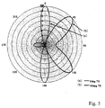
- Figure 5 shows an example of receive directivity patterns of an adaptive array antenna.
- the pattern designated (a) is an example in which the maximum directivity has been adjusted to 0 degrees for reception of an incoming wave from the 0-degree direction
- the pattern designated (b) is an example in which the maximum directivity has been adjusted to 45 degrees for reception of an incoming wave from the 45-degree direction.
- the drawing also shows the directivity component in the 180-direction that is the opposite direction from 0 degree, and the -45-degree direction that is the opposite direction from 45 degrees.
- the desired signal can be received while eliminating interference entering the antenna owing to waves arriving from directions different from the arrival direction of the desired signal.
- the adaptive array antenna has therefore drawn considerable attention as a technology for eliminating interference waves received by the antenna owing to waves arriving from directions different from the arrival direction of the desired signal.
- the adaptive array antenna has therefore drawn considerable attention as a technology for eliminating interference.
- Figure 6 shows an example configuration of a receiver including a path detection circuit used in a conventional base station equipped with an adaptive array antenna.
- the receiver comprises N number (a plural number) of receive paths composed of N number of antennas G1 - GN constituting an adaptive array antenna, N number of receiver units (RX) H1 - HN each associated with one of the antennas G1 - GN, and N number of user separators I1 - IN each associated with one of the antennas G1 - GN (and one of the receiver units H1 - HN).
- the illustrated receiver also includes a user-segregated AAA signal processor and discriminator 41 common to the N number of receive paths.
- the illustrated receiver is further equipped with a path detection circuit composed of an antenna 42, receiver unit 43, spreading code generator 44, correlator 45, delay profile analyzer 46 and path detector 47.
- Each of the N number of antennas G1 - GN receives wireless signals.
- Each of the N number of receiver units H1 - HN down-converts the input signals from the associated antenna G1 - GN from a carrier frequency band signal to a baseband signal and outputs the down-converted signal to the associated user separator I1 - IN.
- receiver units H1 - HN down-convert the input signals from the antennas G1 - GN to baseband signals and then output the baseband signals to the user separators I1 - IN, other configurations are also usable.
- the user separators I1 - IN include multiple correlators (commonly referred to as "fingers”) in a number equal to ( ⁇ number of users (mobile stations) ⁇ ⁇ ⁇ number of paths per user ⁇ ), which they use to separate the signals input from the associated receiver units H1 - HN into signals of the individual users and individual paths. They then output the separated signals (user-separated signals) to the user-segregated AAA signal processor and discriminator 41.
- FIG. 7 shows an example configuration of the correlators provided in the user separators I1 - IN.
- the correlator is equipped with a user-segregated spreading code generator 51, complex multiplier 52, synthesizer (adder) 53, delay element 54 and switch 55.
- the user-segregated spreading code generator 51 generates a user-specific spreading code defined for each user and outputs the generated spreading code to the complex multiplier 52.
- the complex multiplier 52 performs complex-multiplication on the spreading code from the user-segregated spreading code generator 51 and the signal from the associated receiver unit H1 - HN every chip and outputs the result of the multiplication to the synthesizer 53.
- the synthesizer 53 synthesizes (adds) the multiplication result for every chip input from the complex multiplier 52 and the output of the delay element 54 (explained later) and outputs the result of the synthesis.
- the switch 55 is controlled by, for instance, a controller to open for one spreading code period of the user and to close when the period has elapsed.
- the switch 55 is open, the synthesis result output by the synthesizer 53 is input to the delay element 54.
- the switch 55 is closed, the synthesis result output by the synthesizer 53 is output through the switch 55 to the user-segregated AAA signal processor and discriminator 41.
- the delay element 54 delays the synthesis result received from the synthesizer 53 by a prescribed time period and outputs it to the synthesizer 53.
- the multiplication results output by the complex multiplier 52 for a number of successive spreading code chips are cumulatively synthesized by the synthesizer 53 and the cumulative synthesis result is output through the switch 55 to the user-segregated AAA signal processor and discriminator 41.
- the cumulative synthesis results output through the switches 55 of the respective user separators I1 - IN correspond to the result of correlating the signals output by the user separators I1 - IN and the respective user spreading codes (despreading result) and thus correspond to signals separated by user and path.
- the user-segregated AAA signal processor and discriminator 41 includes a user-segregated AAA signal processor and a discriminator.
- the user-segregated AAA signal processor multiplies the user separated signals received from the user separators I1 - IN and individual user receive weights (complex coefficients for weighting) and acquires the synthesized (summed) result of the multiplication results (in this example, N number of multiplication results based on the outputs from the antenna paths) as the adaptive array antenna receive result.
- the discriminator discriminates the received data based on the synthesis result acquired by the user-segregated AAA signal processor and outputs the discriminated individual user data signals as demodulated signals (from the user-segregated AAA signal processor and discriminator 41).
- the user-segregated AAA signal processor and discriminator 41 thus outputs the user data of each of M number (M being one or greater) of users.
- the antenna 42 of the path detection circuit receives a wireless signal.
- the receiver unit 43 of the path detection circuit down-converts the input signal from the antenna 42 from a carrier frequency band signal to a baseband signal and outputs the down-converted signal to the correlator 45.
- the receiver unit 43 down-converts the input signal from the antenna 42 to a baseband signal and the baseband signal is thereafter subjected to correlation processing in the correlator 45, other configurations are also usable.
- the spreading code generator 44 generates user-specific spreading codes defined for the respective users and outputs the generated spreading codes to the correlator 45.
- the correlator 45 correlates the signal received from the receiver unit 43 with the spreading code received from the spreading code generator 44 and outputs the correlation result to the delay profile analyzer 46.
- a matched filter is generally used as the correlator 45.
- the matched filter is an infinite impulse response (FIR) filter.
- FIR infinite impulse response
- its multiplication coefficient is the user-specific spreading code supplied by the spreading code generator 44.
- FIG 8 shows an example configuration of the correlator (MF) 45 and a spreading code generator 61 that corresponds to the spreading code generator 44 shown in Figure 6.
- the correlator 45 comprises L number of series-connected shift registers J1 - JL, L number of complex multipliers K1 - KN each connected to the output of one of the shift registers J1 - JL, and a synthesizer 62.
- L is equal to the number of chips contained in one spreading code.
- the first shift register J1 receives the signal from the receiver unit 43 (e.g., an I signal or Q signal). It outputs the signal to the first complex multiplier K1 and, after a prescribed delay time, also outputs it to the second shift register J2.
- the receiver unit 43 e.g., an I signal or Q signal.
- the Lth shift register JL receives the signal output by the (L-1)th shift register JL - 1 and outputs it to the Lth complex multiplier KL.
- the spreading code generator 61 outputs L number of values (e.g., 1 and 0 values) corresponding to the L number of chips making up one spreading code to the complex multipliers K1 - KL, using a bus line, for example.
- the complex multipliers K1 - KL perform complex multiplication on the signal values input from the shift registers J1-JL and the values input from the spreading code generator 61 and output the multiplication results to the synthesizer 62.
- the synthesizer 62 synthesizes the L number of multiplication results received from the L number of complex multipliers K1 - KL and outputs the synthesis result to the delay profile analyzer 46.
- the correlator 45 successively correlates the received signals (their I or Q signals) from the antenna 42 with the spreading codes.
- the spread spectrum signal contained in the received signal (its spreading code) and the spreading code output by the spreading code generator 44 (61) match in phase, a sharp autocorrelation peak peculiar to the spreading code appears in the output of the correlator 45.
- an autocorrelation peak of the delayed-wave appears in the output of the correlator 45 at a point shifted timewise from the leading wave autocorrelation peak by the delay time of the delayed-wave path.
- Figure 9 shows an example of the correlation result output by the correlator 45.
- Relative delay time is represented on the horizontal axis of the graph and the output level (receive level) of the correlation result on the vertical axis.
- the correlation result shown by the graph indicates the delay profile of the propagation path. Specifically, in this example, one delayed-wave has occurred relative to the leading wave in the propagation path and, as a result, two autocorrelation peaks have appeared.
- a time-averaged delay profile acquired by causing the delay profile analyzer 46 to average the correlation result received from the correlator 45 over time is output to the path detector 47.
- Figure 10 shows an example of cumulatively summed and averaged output of the correlator 45 (averaged data) and an example of a threshold Q explained below.
- the horizontal axis of the graph represents relative delay time and the vertical axis averaged data P and threshold Q.
- the path detector 47 sets an appropriate threshold Q with respect to the averaged delay profile received from the delay profile analyzer 46. Paths and noise are distinguished by defining averaged data P portions exceeding the threshold Q as autocorrelation peaks and defining averaged data portions equal to or lower than the threshold Q as noise portions. This enables detection of the path arrival times (leading wave and delayed-wave arrival times).
- the so-detected path arrival times are, for example, imparted to the correlators (fingers) in the user separators I1 - IN.
- the correlators can therefore generate spreading codes synchronously with the path arrival times and use them to carry out the correlation processing.
- the generation of the spreading codes with such timing establishes synchronization that constantly enables maximum value autocorrelation peaks of the desired incoming waves to be acquired in the correlation processing.
- the detection circuit of a conventional CDMA receiver equipped with an adaptive array antenna has a drawback in that the path detection accuracy in the path detector 47 is low because no adaptive array antenna processing is applied in the path detection.
- transmission power control is conducted that makes it possible to reduce the transmission power required to communicate with a receiver using an adaptive array antenna and capable of interference level reduction (compared with the case of not using an adaptive array antenna).
- the receiver can enhance the received signal quality by using the adaptive array antenna to receive and process the signal.
- the path detector 47 is not equipped with an adaptive array antenna. This not only prevents improvement of the path detection accuracy but also leads to degraded path detection accuracy when the transmission power is reduced.
- the conventional receiver would be able utilize the adaptive array antenna to enable reduction of transmission power on the transmission side if the detection of path timing were as accurate as it might be.
- the accuracy of path detection decreases to the point that the timing of autocorrelation peaks cannot be accurately detected. This makes it impossible to lower the transmission power.
- the transmission power cannot be reduced is the same as saying that the transmission power per user increases.
- the maximum number of mobile stations (users) that a base station can accommodate decreases. This is a serious problem.
- the conventional CDMA system utilizing the adaptive array antenna thus requires high transmission power to prevent degradation of path detection accuracy, it therefore has the drawback of small system capacity. That is, the enhanced demodulation accuracy of a system utilizing the adaptive array antenna as a rule enables lowering of the transmission power on the transmission side, but reduction of the transmission power lowers the signal-to-noise ratio (SNR) of the conventional receiver described in the foregoing with respect to the received signal and makes it incapable of accurate path detection. Reduction of transmission power is therefore impossible.
- SNR signal-to-noise ratio
- the present invention was accomplished in light of the foregoing circumstances and has as an object to provide a receiver, CDMA receiver and CDMA base station that enhance received signal path detection accuracy when receiving a signal arriving via multiple paths using multiple antennas.
- Another object the present invention is to provide a path detector and a path detection method that enhance received signal path detection accuracy.
- the present invention achieves the foregoing objects by providing a receiver that, when receiving signals arriving via multiple paths using multiple antennas, detects the paths of the received signals in the following manner.
- receive weight generating means generates receive weights for every antenna based on signals received from the antennas
- summing means calculates the sums of the results obtained by multiplying the signals from the antennas and the receive weights of the individual antennas generated by the receive weight generating means
- path detection means detects the paths of the received signals based on the sums calculated by the summing means.
- the invention amounts to applying adaptive array antenna technology to path detection and, as such, enhances received signal path detection accuracy and improves reception quality.
- this invention does not generate a voltage profile for every antenna but instead calculates the sum of the results obtained by multiplying the signals from the antennas and the receive weights of the individual antennas and then detects the paths of the received signals based on the sum. Because of this, there is no need to calculate voltage profiles for the individual antennas and accordingly no need to provide a voltage profile calculating section for every antenna. This means that the physical configuration can be made small as compared with the path detection method proposed in Reference A, for example.
- any of various types of antennas can be used.
- various numbers of the antennas are usable and any of various antenna array configurations can be used.
- the receive weights calculated for receive-processing involving weighting and synthesis of the received signals from the respective antennas are preferably also used for path detection.
- the receive weight generating means generates receive weights for each of multiple paths
- the summing means calculates a sum for each of the multiple receive weights
- the path detection means detects the paths of the received signals based on the multiple sums calculated by the summing means.
- the receive weights generated by the receive weight generating means generally differ between different paths.
- the number of paths for which receive weights are generated by the receive weight generating means can be any of various numbers greater than one.
- any of various modes of detecting the received signal paths based on the multiple sums can be used. For example, there can be adopted a mode in which the paths of the received signals are detected based on one member selected from among the sum of the leading wave path, the sum of the highest level path, the sum of the lowest level path, and the sum calculated with the average of the receive weights of all paths (averaged receive weights).
- a mode in which the paths of the received signals are detected based on two or more of said members can also be adopted.
- the receiver of the present invention can be configured such that the summing means calculates two or more members among the sum of the leading wave path, the sum of the highest level path, the sum of the lowest level path, and the sum calculated with the average of the receive weights of all paths, and the path detection means detects the paths of the received signals for every sum produced by the summing means, selects one of the sums produced by the summing means based on a comparison of the detected number of paths and the detected path levels with prescribed conditions relating to these, and detects the received signal paths based on the selected sum.
- Any two or more members can be selected for use from among the sum of the leading wave path, the sum of the highest level path, the sum of the lowest level path, and the sum calculated with the average of the receive weights of all paths.
- the conditions relating to the number of detected paths and their path levels can be any of various conditions.
- a detected path number threshold and a detected path level threshold can be used as the conditions.
- Methods that can be adopted in the path detection means for selecting one of the sums produced by the summing means include that of conducting received signal path detection for all of the sums produced by the summing means and selecting one of the sums based on the result of the detection and that of establishing a priority sequence regarding the order in which the sums produced by the summing means are to be used for path detection and successively selecting one sum from among the sums based on the priority sequence. Further, an arrangement can be adopted in which the path detection processing is repeated when one or both of the number of detected paths and the detected path level does not satisfy the prescribed condition.
- the summing means comprises at least one multiplier that time-division multiplies the signals from the antennas and the receive weights of the individual antennas generated by the receive weight generating means and a synthesizer that sums the multiplication results for the individual antennas produced by the multiplier.
- the number of multipliers can be reduced and the size of the circuit decreased.
- the at least one multiplier used for the time-division multiplication may be any number of multipliers.
- the time-divided multiplication may be carried out in any of various modes.
- the receiver of the present invention described in the foregoing can be preferably applied in a CDMA receiver for receiving Wideband-CDMA or other such CDMA spread spectrum signals over the airwaves.
- the spread spectrum signals contained in the received signals can be detected (e.g., dispread) for every path based on the received signal path detection result.
- the receiver of the present invention described in the foregoing can be preferably applied in a CDMA base station for receiving Wideband-CDMA or other such CDMA spread spectrum signals over the airwaves.
- the receiver of the foregoing description receives spread spectrum signals from multiple mobile stations (users) that transmit CDMA spread spectrum signals over the airwaves, detects the received signal paths for every mobile station, and detects (e.g., despreads) the spread spectrum signals contained in the received signals for every mobile station and every path based on the detection result.
- a base station is generally defined as being capable of wireless communication with multiple mobile stations.
- the number of mobile stations with which the CDMA base station of this invention can communicate is not particularly limited.
- the present invention by enabling path detection utilizing the configuration and method described in the foregoing, provides a path detector and a path detection method capable of enhancing the received signal path detection accuracy.
- the path detector of the present invention is configured so that in detecting the paths of signals arriving via multiple paths received by multiple antennas, the paths of the received signals are detected based on sums of the results obtained by multiplying the signals from the antennas and receive weights of the individual antennas.
- the path detection method of the present invention is configured so that in detecting the paths of signals arriving via multiple paths received by multiple antennas, the paths of the received signals are detected based on sums of the results obtained by multiplying the signals from the antennas and receive weights of the individual antennas.
- the path detection circuit and the path detection method of the present invention are preferable for application to a CDMA receiver, a CDMA base station or the like that receives signals using multiple antennas.
- a CDMA base station equipped with a CDMA receiver that is a first embodiment of this invention will be explained first.
- Figure 1 shows the configuration of a receiver with path detection circuit (path detector) used in the CDMA base station with adaptive array antenna of the example that will be explained here.
- path detector path detection circuit
- the illustrated receiver comprises N number of receive paths composed of N number of antennas A1 - AN constituting an adaptive array antenna, N number of receiver units (RX) B1 - BN each associated with one of the antennas A1 - AN, and N number of user separators C1 - CN each associated with one of the antennas A1 - AN (and one of the receiver units B1 - BN).
- the illustrated receiver also includes a user-segregated AAA signal processor and discriminator 1 common to the N number of receive paths.
- the illustrated receiver is further equipped with a path detection circuit composed of N number of complex multipliers D1 - DN, a synthesizer 2, spreading code generator 3, correlator 4, delay profile analyzer 5, and path detector 6.
- the configuration and operation of the receiver installed in a CDMA base station of this embodiment are, except for the configuration and operation of the path detection circuit, the same as the configuration and operation of the receiver shown in Figure 6.
- the portions of the configuration and operation that are the same will therefore not be explained with respect to this embodiment and only the portions thereof that are different will be explained in detail.
- an adaptive array antenna is applied in the path detection circuit of the receiver of this embodiment, such application of an adaptive array antenna in the path detection circuit of this invention is valid only with respect to users that apply receive processing using an adaptive array antenna (AAA signal processing).
- AAA signal processing an adaptive array antenna
- This embodiment is characterized in that the AAA signal processing performed by the user-segregated AAA signal processor and discriminator 1 is applied to the path detection circuit.
- AAA signal processing as shown for example in Figure 7, the multiplication of the signals separated by user (despread signals) by the receive weights is generally carried out for every user, path and antenna, and the results of the multiplication are synthesized for each user and path.
- the weights are usually calculated using the normalized-least mean square (N-LMS) algorithm.
- N-LMS normalized-least mean square
- the user-segregated AAA signal processor and discriminator 1 uses an algorithm such as that just mentioned to calculate receive weights for the individual user signals and then outputs to the respective complex multipliers D1 - DN the receive weights of the individual antennas A1 - AN obtained with respect to the user signals whose delay profiles are to be next analyzed by the path detection circuit.
- FIG. 2 shows an example of the user-segregated AAA signal processor of the user-segregated AAA signal processor and discriminator 1.
- the user-segregated AAA signal processor comprises N number of complex multipliers E1 - EN, a synthesizer 11 for summing the multiplication results, a synthesizer 12 for control, and a weight computing unit 13.
- the input signal from each of the antennas A1 - AN for a prescribed path of a prescribed user is sent from the associated receiver unit B1 - BN to the associated user separator C1 - CN and the result of correlation processing by the correlator of the user separator C1 - CN is input to an associated one of the complex multipliers E1 - EN.
- the complex multipliers E1 - EN are also input with receive weights calculated for the respective antennas A1 - AN by the weight computing unit 13 (explained below).
- Each complex multiplier E1 - EN multiples the correlation result input from the associated antenna A1 - AN and the receive weight for the associated antenna A1 - AN, and sends the multiplication result to the synthesizer 11.
- the synthesizer 11 synthesizes the N number of multiplication results received from the N number of complex multipliers E1 - EN and outputs the synthesis result to the discriminator as a received signal subjected to signal processing by the adaptive array antenna.
- the synthesizer 11 also outputs the synthesis result to the synthesizer 12.
- a data signal of the aforesaid prescribed user acquired from the discriminator, for example, is also input to the synthesizer 12 as a reference signal.
- the synthesizer 12 inverts the output signal from the synthesizer 11 and synthesizes the inverted output signal with the reference signal, thereby outputting to the weight computing unit 13 an error signal that is the result obtained by subtracting the output signal of the synthesizer 11 from the reference signal.
- the weight computing unit 13 is constituted as a digital signal processor (DSP), for example. By successive updating or the like, it calculates for the respective antennas A1 - AN receive weights that reduce (preferably minimize) the error signal received from the synthesizer 12. The receive weights calculated for the individual antennas A1 - AN are output to the complex multipliers E1 - EN.
- DSP digital signal processor
- the complex multipliers D1 - DN are input with the signals sent from the receiver units B1 - BN to the user separators C1 - CN.
- the complex multipliers D1 - DN multiply the signals received from the associated receiver units B1 - BN and the receive weights of the associated antennas A1 - AN received from the user-segregated AAA signal processor and discriminator 1, and output the multiplication results to the synthesizer 2.
- the synthesizer 2 synthesizes the N number of multiplication results received from the N number of complex multipliers D1 - DN and outputs the synthesis result to the correlator 4.
- the spreading code generator 3, correlator 4, delay profile analyzer 5 and path detector 6 utilize the synthesis result received from synthesizer 2, for example in a manner similar to the path detection circuit shown in Figure 5, to carry out correlation between the synthesis result and the spreading code, analyze the delay profile obtained by time-averaging the correlation result, and detecting the path of the received signal based on the averaged delay profile.
- the combination of the multiplication by the complex multipliers D1 - DN and the synthesis by the synthesizer 2 amounts to signal processing equivalent to that by an adaptive array antenna.
- the optimum receive directivity obtained with an adaptive array antenna using an algorithm such as N-LMS e.g., receive directivity that maximizes receive gain in the direction of the desired incoming wave and directs a null in the direction of an undesired incoming wave
- N-LMS e.g., receive directivity that maximizes receive gain in the direction of the desired incoming wave and directs a null in the direction of an undesired incoming wave
- a conventional path detection circuit such as that shown in Figure 6 experiences a decrease in path detection accuracy because in the absence of signal processing by an adaptive array antenna the interference in the path detector 47 reaches a level that is not negligible.
- the path detection circuit of this embodiment achieves improved path detection accuracy because the adoption of a detection method that applies signal processing by an adaptive array antenna ensures removal of interference waves at the time of path detection.
- the "Different Configuration" As a path detection circuit differing in configuration from that of this embodiment (hereinafter the "Different Configuration"), it is conceivable, for example, to provide N number of correlators (like the correlator 4) equal to the number of antennas A1 - AN, as in a receive processing system using an adaptive array antenna, to send the output signals from the receiver units (like the receiver units B1 - BN) to the N number of correlators, and to provide as stages following the correlators complex multipliers (like the complex multipliers D1 - DN) and a synthesizer (like the synthesizer 2).
- the N number of correlators correlate the output signals from the receiver units with the spreading codes
- the N number of complex multipliers multiply the outputs from the correlators and the receive weights of the individual antennas
- the synthesizer synthesizes the N number of multiplication results
- a delay profile analyzer (like the delay profile analyzer 5) analyzes a time-averaged delay profile based on the synthesis result
- a path detector (like the path detector 6) detects the received signal based on the averaged delay profile.
- the receiver installed in a CDMA base station of this embodiment adopts a configuration including an adaptive array antenna composed of multiple antennas A1 - AN, wherein each of the antennas A1 - AN is imparted with a receive weight and weighting/synthesis processing is applied to path detection.
- the signals received using the multiple antennas A1 - AN are used to calculate a receive weight for each of the antennas A1 - AN
- the signals received by the antennas A1 - AN and the receive weights calculated for the individual antennas A1 - AN are multiplied, and path detection is conducted based on the result of summing the multiple multiplication results.
- the receive weights of the individual antennas A1 - AN are calculated for each user and the receive weights calculated for a given user are used for path detection of that user.
- the circuit configuration includes a circuit for signal receive processing that comprises N number of antennas A1 - AN that each transmits/receives carrier frequency band signals, N number of receiver units B1 - BN that down-convert the outputs (received signals) of the N number of antennas A1 - AN to baseband (or, for example, intermediate frequency (IF)) signals, N number of user separators C1 - CN that separate (e.g, despread) the outputs of the N number of receiver units B1 - BN into individual user signals taken in in accordance with the principle of the CDMA system, and a user-segregated AAA signal processor and discriminator 1 that discriminates data resulting from synthesis of the outputs of the N number of user separators C1 - CN by adaptive array antenna signal processing, thereby outputting receive data for each of M number of users.
- IF intermediate frequency
- the receiver of this embodiment further includes a circuit for path detection comprising N number of complex multipliers D1 - DN that complex-multiply the outputs of the aforesaid N number of receiver units B1 - BN and receive weights for the individual antennas A1 - AN calculated by the aforesaid user-segregated AAA signal processor and discriminator 1, a synthesizer 2 that synthesizes the outputs of the N number of complex multipliers D1 - DN, a correlator 4 that extracts (despreads) the signal of a desired user from the output of the synthesizer 2, a spreading code generator 3 that outputs the spreading code of the desired user to the correlator 4, a delay profile analyzer 5 that analyzes the output of the correlator 4 to obtain a delay profile, and a path detector 6 that detects a significant incoming wave from the output of the delay profile analyzer 5.
- a circuit for path detection comprising N number of complex multipliers D1 - DN that complex-
- the receiver installed in a CDMA base station of this embodiment calculates receive weights for every user, path and antenna from the signals received by the antennas A1 - AN and uses one of the calculated weight sets for path detection to detect the path of the received signal for each user.
- the receiver installed in a CDMA base station of this embodiment achieves improved path detection accuracy relative to the prior art and, by this, enables reduction of the transmission power of mobile stations and the like, which reduction in turn enables enhancement of system capacity.
- the path detection circuit of the configuration according to this embodiment conducts adaptive array antenna signal processing at a stage prior to the correlator 4, the number of correlators can, as explained earlier, be reduced compared with the case of conducting the signal processing at a stage following the correlator(s).
- the N number of antennas A1 - AN that receive one and the same user signal arriving via multiple paths in this embodiment correspond to the "multiple antennas" of the present invention.
- the capability of the user-segregated AAA signal processor and discriminator 1 to calculate (generate) receive weights of the antennas A1 - AN based on the signals it receives from the antennas A1 - AN via the receiver units B1 - BN and the user separators C1 - CN in this embodiment constitutes the "receive weight generating means" of the present invention.
- the capability of the N number of complex multipliers D1 - DN to multiply the input signals from the antennas A1 - AN and the receive weights of the individual antennas A1 - AN and of the synthesizer 2 to sum (synthesize) the multiplication results in this embodiment constitutes the "summing means" of the present invention.
- the capability of the spreading code generator 3, correlator 4, delay profile analyzer 5 and path detector 6 to detect received signal path based on the result of the summing in this embodiment constitutes the "path detection means" of the present invention.
- CDMA base station equipped with CDMA receiver that is a second embodiment of the present invention will now be explained.
- the receiver installed in the CDMA base station of this embodiment is characterized in how the receive weights are imparted from the user-segregated AAA signal processor and discriminator 1 to the complex multipliers D1 - DN of the path detection circuit.
- the receiver of this embodiment has the same configuration as that of the first embodiment shown in Figure 1, no detailed explanation of the configuration will be given.
- sets of receive weights can be calculated for the incoming waves arriving via multiple paths (e.g., four sets can be calculated when there are four antennas and three paths).
- the path detection circuit since the path detection circuit operates in the state prior to separation of the signal into the respective paths, only one type of receive weights can be applied to the path detection circuit at any given time point. For example, even when the number of incoming waves arriving via multiple paths (number of paths) is three and there are three sets of weights, only one set of receive weights can be applied to the path detection circuit.
- the methods (1) to (4) can be expected to produce different effects. For instance, in mobile communications, in which the delay profile of the propagation paths changes from moment to moment, the optimum receive weight can be considered to vary with time.
- the receiver of this embodiment deals with this situation by switching among the options (1) to (4) based on the result of path detection. For example, an appropriate receive weight is applied to the path detection circuit in response to change in the delay profile of the propagation paths.
- Figure 3 is a flow chart showing the sequence of processing steps for changing the receive weight applied to the path detection circuit.
- the receive weight of the leading path for example, is initially selected for application (step S1). This receive weight is applied to the path detection circuit (step S2) and path detection processing is performed by the path detection circuit (step S3).
- step S4 it is discriminated whether the number of paths detected by the path detection processing is equal to or greater than a prescribed threshold (step S4) and checked whether the path level detected by the path detection processing is equal to a predetermined threshold (step 5).
- a prescribed threshold e.g., a predetermined threshold
- the applied weight is changed to, for example, the receive weight of the path of highest level (step S6) and that receive weight is applied to the path detection circuit (step S2). Then, similarly to the foregoing, processing for path detection (step S3) and processing for discriminating the number of paths and the path levels are conducted (steps S4 and S5).
- the applied weight is again changed (step 6), to the average value of the receive weights of all paths, for example. Processing similar to the foregoing is then conducted (steps S2 to S5).
- the applied weight is again changed (step 6), to the receive weight for the path of lowest level, for example.
- step 7 that receive weight is applied, path detection is conducted, and the path detection processing is terminated.
- the receive weight applied to the path detection circuit is changed when the number of detected paths and/or the detected path levels obtained as a result of path detection processing fail to reach prescribed thresholds.
- the path number threshold and the detected path level threshold can be set to any of various values according to the state of system use and the like.
- the path detection processing is repeated when, for example, the number of detected paths and the detected path levels do not reach the thresholds.
- the applied weight option that is optimum for the circumstances is preferably selected.
- path detection processing is again conducted for users for which path detection processing was already done.
- the path detection processing can be conducted by first applying the receive weight of the leading path to the path detection circuit, as shown in Figure 3, more preferably the path detection processing is conducted by, for example, again applying to the path detection circuit the receive weight previously applied to the users concerned.
- identification numbers of the receive weights previously applied to each user can be stored in memory, the identification number associated with the user and stored in memory be retrieved at the time of the next path detection processing for the user, and the receive weight corresponding to the retrieved identification number be applied to the path detection circuit.
- the delay profile analysis and path detection processing for a single user is carried out continuously with the type of receive weight being changed until the number of detected paths and/or the detected path levels reach prescribed thresholds.
- the number of detected paths and/or the detected path levels obtained for a given user do not reach the prescribed thresholds, it possible instead to conduct delay for profile analysis and/or path detection processing with respect to another user, i.e., to alter the priority of users to be subjected to path detection processing.
- the present invention is not limited to the procedure shown in Figure 3 but can employ any of various other detection processing procedures, insofar as the procedure can ensure completion of the path detection processing by the path detection circuit within a prescribed time period defined in light of, for example, the system use state.
- the type of receive weight the user-segregated AAA signal processor and discriminator 1 imparts to the complex multipliers D1 - DN is changed to a different type when the result of path detection does not satisfy prescribed conditions, thereby ensuring that the type of receive weight applied to the path detection circuit provides a sufficient number of detected paths and/or sufficient detected path levels.
- the type of receive weight the user-segregated AAA signal processor and discriminator 1 imparts to the complex multipliers D1 - DN is changed and the path detection processing is repeated within a prescribed time period.
- the path detector 6 is made capable of comparing the detected number of paths and a prescribed number of paths and/or is made capable of comparing the levels of the detected paths and a prescribed path level
- the path detector 6 and/or the user-segregated AAA signal processor and discriminator 1 select, based on the comparison result, one type of receive weight among the receive weight of the leading path, the receive weight of the highest level path, the average value of all path receive weights and the receive weight of the lowest level path, and the path detection result when the selected weight is applied is supplied to the user separators C1 - CN.
- the type of receive weight applied for path detection can be successively changed to select the type of receive weight considered optimum for each user.
- this embodiment makes it possible to avoid situations in which the type of receive weight for one incoming wave among incoming waves arriving via multiple paths is fixed and used constantly and, by this, makes it possible to avoid situations in which an incoming wave is constantly lost in the case where, for instance, the incoming wave is lost when a certain type of weight is applied.
- the user-segregated AAA signal processor and discriminator 1 constituting the receive weight generating means of the present invention generates receive weights for every path of the multiple paths contained in the delay profile
- the complex multipliers D1 - DN and synthesizer 2 constituting the summing means of the present invention sum the receive weights for each of multiple receive weights
- the path detector 6 etc. constituting the path detection means of the present invention detects the paths of the received signals based on the multiple sums.
- the complex multipliers D1 - DN and synthesizer 2 constituting the summing means of the present invention calculate the sum of the leading wave path (sum using the leading wave receive weight), the sum of the highest level path (sum using the highest level path receive weight), the sum of the lowest level path (sum using the lowest level path receive weight) and the sum using the average of the receive weights of all paths), the path detector 6 constituting the path detection means of the present invention detects the received signal path for each summing result (each sum), compares the detected number of paths and/or the detected path levels with prescribed conditions and selects one of the sums based on the result of the comparison, and adopts the received signal path detection result based on the selected sum.
- a CDMA base station equipped with CDMA receiver that is a third embodiment of the present invention will now be explained.
- the receiver installed in the CDMA base station of this embodiment is characterized in the point that the contribution of the complex multipliers to overall physical size is reduced by time-divided use of the complex multipliers for adaptive array antenna signal processing in the path detection circuit.
- the configuration of the receiver of this embodiment is the same as that of the receiver of the first embodiment shown in Figure 1. Constituent portions which are identical with those of the first embodiment will not be explained again here.
- the configuration that achieves maximum reduction of physical size by making time-divided use of the complex multiplier is one that operates the real number multiplier at an operating speed that is four times the total number of antennas A1 - AN faster than the operating speed in the configuration shown in Figure 1 (4 ⁇ N times faster operating speed).
- (4 ⁇ N) multiplications can be done using a single real number multiplier.
- the physical size of a multiplier is generally large.
- a 12 bit ⁇ 12 bit real number multiplier for example, requires around 20 thousand gates.
- the number of gates can be reduced by around 300 thousand.
- Figure 4(a) shows a configuration of the receive weight multiplication and synthesis circuit section when the time-division processing of this embodiment is not applied in a system having a total of four antennas.
- the circuit section is equipped with four complex multipliers F1- F4 and a synthesizer 21.
- the signals A1[t], A2[t], A3[t], A4[t] each received by one of the four antennas #1 - #4 are sent to the complex multipliers F1- F4.
- Each of the complex multipliers F1- F4 is further input with one of receive weights W1[t], W2[t], W3[t], W4[t] corresponding to the antennas #1 - #4.
- the complex multipliers F1- F4 multiply the input signals A1[t] - A4[t] from the antennas #1 - #4 and the receive weights W1[t] - W4[t] and the synthesizer 21 synthesizes the four multiplication results.
- the synthesis result output by the synthesizer 21 is (A1[t] *W1[t] + A2[t] *W2[t] + A3[t] *W3[t] + A4[t] *W4[t]).
- Figure 4(b) shows a configuration of the receive weight multiplication and synthesis circuit section when the time-division processing of this embodiment is applied in a system having a total of four antennas.
- the circuit section is equipped with a multiplexer 31 that converts the parallel signals (four signals) A1[t] - A4[t] received from the four antennas #1 - #4 to four-fold faster serial signals (signals of one quarter time width) and outputs the serial signals to a complex multiplier 33, a multiplexer 32 that converts receive weights (parallel signals composed of four receive weight signals) W1[t] - W4[t] to four-fold faster serial signals (signals of one quarter time width) and outputs the serial signals to the complex multiplier 33, the single complex multiplier 33, a synthesizer 34, a delay element 35 and a switch 36.
- the complex multiplier 33 operates by time division, i.e., by operating at four times faster than in the case of Figure 4(a), the complex multiplier 33 successively outputs the multiplication results for the antennas #1 - #4 to the synthesizer 34 in the order of A1[t] *W1[t], A2[t] *W2[t], A3[t] *W3[t], A4[t] *W4[t].
- the synthesizer 34 synthesizes the multiplication results received from the complex multiplier 33 and the output of the delay element 35 and outputs the synthesis result.
- the switch 36 closes once for each period of the four antennas #1 - #4 (e.g., once every four clock pulses) and opens within the same period.
- the output of the synthesizer 34 is returned to the synthesizer 34 via the delay element 35 when the switch 36 is open and, therefore, the synthesizer 34 and the delay element 35 cumulatively synthesize four multiplication results from the complex multiplier 33 corresponding to the four antennas #1 - #4.
- the desired signal can be obtained from the adaptive array antenna, and when the switch 36 opens once every fourth clock pulse, the data of the cumulative synthesis can be made determinate and output via the switch 36.
- the determinate data are the same as those indicated with respect to Figure 4(a): (A1[t] *W1[t] + A2[t] *W2[t] + A3[t] *W3[t] + A4[t] *W4[t]).
- the data retained by the delay element 35 is reset once every four cycles (e.g., once every four clock pulses) to prevent the retained data from spilling over to an adjacent time region.
- the synthesizer 34 is equipped with the delay element 35 and included in the time-division operation in order to reduce the number input terminals of the synthesizer 34.
- a multiplexer is provided ahead of the synthesizer 34 for converting the multiplication results output by the complex multiplier 33 from a serial signal to parallel signals (four signals in this example)
- synthesis can be done using a configuration like that of the synthesizer 21 shown in Figure 4(a).
- the processing for complex-multiplying the signals from the antennas A1 - AN and the receive weights of the individual antennas A1 - AN is time divided so that the multipliers can be reduced to a small number, such as one or two, that are used for time-division processing.
- the physical size of the system can be reduced in comparison with the prior art.
- the complex multiplier 33 that multiplies the signals received from the antennas and the receive weights of the individual antennas by time-division operation constitutes the multiplier of the present invention
- the synthesizer 34 that synthesizes (sums) the multiplication results for the respective antennas produced by the complex multiplier 33 constitutes the synthesizer of the present invention.
- W-CDMA wideband code division multiple access
- W-CDMA has attracted attention as a next-generation mobile communication system.
- the W-CDMA world standard includes use of the adaptive array antenna as a specification option, making adaptive array antenna utilization possible at the discretion of the operator.
- Application of the present invention W-CDMA base station makes it possible to structure a cellular telephone network that can reduce the transmission power of the mobile stations and boost capacity.
- the receiver is, for example, configured as described regarding the earlier embodiments, and when the spread spectrum signal is received over the airwaves, the spread spectrum signal contained in the received signal is detected for every path based on the result of received signal path detection.
- the CDMA base station is equipped with, for example, a receiver like that described regarding the earlier embodiments, CDMA system spread spectrum signals transmitted from multiple mobile station (users) are received by the receiver, the received signal paths are detected for each mobile station, and the spread spectrum signals contained in the received signal are detected for every mobile station and every path based on the result of the detection result.
- detection of the paths of signals arriving via multiple paths and received by multiple antennas is conducted based on the sum of results obtained by multiplying the signals received from the antennas and receive weights of the individual antennas.
- the receiver, CDMA receiver, CDMA base station, path detector and path detection method of the present invention are not limited to the arrangements and configurations described in the foregoing but can be modified in various ways.
- the present invention is not limited to the field of application described in the foregoing but can also be applied in various other fields.
- the various types of processing carried out in the receiver, CDMA receiver, CDMA base station, path detector and path detection method of the present invention can, for example, be conducted by physical means equipped with a processor, memory and the like wherein the processor controls the processing by executing a control program stored in a ROM. Otherwise it can be conducted by independent physical circuits constituting functional means for executing the different processing operations.
- the present invention can be construed as being constituted of the aforesaid control program or of a floppy disk, CD-ROM or other computer-readable recording medium storing the control program, and the processing according to the present invention can be carried out by loading the control program from the recording medium into a computer and executing it by use of the processor.
- the receiver, CDMA receiver, CDMA base station, path detector and path detection method according to the present invention are configured so that when signals arriving via multiple paths are received by multiple antennas, receive weights are generated for each antenna based on the signals coming in from the antennas, the results obtained by multiplying the signals from the antennas and the receive weights of the individual antennas are summed, and the paths of the received signals are detected based on the obtained sum.
- received signal path detection accuracy can be enhanced by a simple configuration, thereby providing an improvement in reception quality.
- the receiver etc. generate receive weights for each path among multiple paths, calculate the sum of the receive weights of each type among the multiple types of receive weights, and detect the paths of the received signals based on the multiple sums calculated. This is accomplished, for example, by calculating two or more among the sum of the leading wave path, the sum of the highest level path, the sum of the lowest level path and the sum calculated with the average of the receive weights of all paths, detecting the received signal path for each of the summing results (sums), selecting one of the sums based on a comparison of the detected number of paths and/or the detected path levels with prescribed conditions, and detecting the received signal path based on the selected sum.
- received signal path detection accuracy can be further enhanced in mobile communications, for example.
- the receiver etc. according to the present invention are configured to multiply the signals received from the antennas and receive weights generated for the individual antennas by time-division operation of at least one multiplier and to sum the multiplication results for the individual antennas produced by the multiplier.
- the number of multipliers can therefore be reduced to reduce the physical size of the hardware.
Landscapes
- Engineering & Computer Science (AREA)
- Computer Networks & Wireless Communication (AREA)
- Signal Processing (AREA)
- Radio Transmission System (AREA)
- Mobile Radio Communication Systems (AREA)
- Variable-Direction Aerials And Aerial Arrays (AREA)
Applications Claiming Priority (2)
| Application Number | Priority Date | Filing Date | Title |
|---|---|---|---|
| JP2000372570 | 2000-12-07 | ||
| JP2000372570A JP2002176384A (ja) | 2000-12-07 | 2000-12-07 | 受信機 |
Publications (2)
| Publication Number | Publication Date |
|---|---|
| EP1220474A2 true EP1220474A2 (de) | 2002-07-03 |
| EP1220474A3 EP1220474A3 (de) | 2004-09-22 |
Family
ID=18842095
Family Applications (1)
| Application Number | Title | Priority Date | Filing Date |
|---|---|---|---|
| EP20010308093 Withdrawn EP1220474A3 (de) | 2000-12-07 | 2001-09-24 | Adaptive gruppenempfänger |
Country Status (4)
| Country | Link |
|---|---|
| US (1) | US6968169B2 (de) |
| EP (1) | EP1220474A3 (de) |
| JP (1) | JP2002176384A (de) |
| HK (1) | HK1043706A1 (de) |
Families Citing this family (20)
| Publication number | Priority date | Publication date | Assignee | Title |
|---|---|---|---|---|
| JP2003046418A (ja) * | 2001-08-03 | 2003-02-14 | Uniden Corp | ダイバーシチ受信装置 |
| US20030171834A1 (en) * | 2002-03-07 | 2003-09-11 | Silvester Kelan C. | Method and apparatus for connecting a portable media player wirelessly to an automobile entertainment system |
| JP3895228B2 (ja) * | 2002-05-07 | 2007-03-22 | 松下電器産業株式会社 | 無線通信装置および到来方向推定方法 |
| JP4217043B2 (ja) * | 2002-09-20 | 2009-01-28 | 京セラ株式会社 | アダプティブアレイ無線通信装置、受信レベル表示方法、受信レベル調整方法、受信レベル表示プログラム、および受信レベル調整プログラム |
| JP4309110B2 (ja) | 2002-09-27 | 2009-08-05 | パナソニック株式会社 | 適応アンテナ無線通信装置 |
| JP4090331B2 (ja) | 2002-11-20 | 2008-05-28 | 三洋電機株式会社 | 受信方法と装置 |
| JP2005094143A (ja) * | 2003-09-12 | 2005-04-07 | Uniden Corp | ダイバーシチ受信装置 |
| JP4489460B2 (ja) * | 2004-02-27 | 2010-06-23 | 京セラ株式会社 | 適応アレーアンテナシステム及び適応アレーアンテナ制御方法、無線装置 |
| KR100995542B1 (ko) * | 2005-12-23 | 2010-11-19 | 노키아 코포레이션 | 분산 스펙트럼 신호의 수신에서의 상관 수행 |
| JP4802163B2 (ja) * | 2007-09-03 | 2011-10-26 | 株式会社東芝 | マルチパス等化器を有する受信機及び方法 |
| JP4864926B2 (ja) * | 2008-03-28 | 2012-02-01 | 株式会社東芝 | アレイアンテナ |
| JP5505178B2 (ja) * | 2009-11-02 | 2014-05-28 | 日本電気株式会社 | 無線通信装置、無線通信装置の受信レベル判別方法及びプログラム |
| JP5599677B2 (ja) * | 2010-08-18 | 2014-10-01 | ラピスセミコンダクタ株式会社 | ダイバシティ受信装置及びダイバシティ受信方法 |
| JP5536614B2 (ja) * | 2010-10-27 | 2014-07-02 | 京セラ株式会社 | 通信装置及び通信方法 |
| JP5230766B2 (ja) * | 2011-03-17 | 2013-07-10 | パナソニック株式会社 | 到来方向推定装置及び到来方向推定方法 |
| FI125462B (en) * | 2013-01-29 | 2015-10-15 | Inverpolis Oy | A method and system for using a phased antenna field |
| US9813045B2 (en) * | 2014-09-17 | 2017-11-07 | Microseni Semiconductor ULC | Precision frequency monitor |
| CN107431525B (zh) * | 2015-02-17 | 2020-07-28 | 三菱电机株式会社 | 接收装置和接收方法 |
| US10270481B1 (en) * | 2015-12-22 | 2019-04-23 | Amazon Technologies, Inc. | Wireless communication receiver gain management system |
| US10425860B2 (en) * | 2017-11-03 | 2019-09-24 | Netsia, Inc. | System and method for value optimized mobile networks |
Citations (4)
| Publication number | Priority date | Publication date | Assignee | Title |
|---|---|---|---|---|
| EP0806844A1 (de) * | 1995-11-29 | 1997-11-12 | Ntt Mobile Communications Network Inc. | Diversity-empfänger und zugehöriges steuerverfahren |
| GB2343817A (en) * | 1998-09-30 | 2000-05-17 | Nec Corp | Allocating paths to fingers in a CDMA rake receiver |
| WO2000033481A1 (en) * | 1998-11-30 | 2000-06-08 | Fujitsu Limited | Receiving apparatus including adaptive beamformers |
| WO2000035123A1 (en) * | 1998-12-11 | 2000-06-15 | Nortel Networks Limited | Method and apparatus for high rate data communication utilizing an adaptive antenna array |
Family Cites Families (2)
| Publication number | Priority date | Publication date | Assignee | Title |
|---|---|---|---|---|
| JP2914445B2 (ja) * | 1997-08-05 | 1999-06-28 | 日本電気株式会社 | Cdma適応受信装置 |
| JP2991179B2 (ja) * | 1998-01-08 | 1999-12-20 | 日本電気株式会社 | Cdmaマルチユーザ受信装置 |
-
2000
- 2000-12-07 JP JP2000372570A patent/JP2002176384A/ja active Pending
-
2001
- 2001-09-20 US US09/955,982 patent/US6968169B2/en not_active Expired - Fee Related
- 2001-09-24 EP EP20010308093 patent/EP1220474A3/de not_active Withdrawn
-
2002
- 2002-07-16 HK HK02105230.7A patent/HK1043706A1/zh unknown
Patent Citations (4)
| Publication number | Priority date | Publication date | Assignee | Title |
|---|---|---|---|---|
| EP0806844A1 (de) * | 1995-11-29 | 1997-11-12 | Ntt Mobile Communications Network Inc. | Diversity-empfänger und zugehöriges steuerverfahren |
| GB2343817A (en) * | 1998-09-30 | 2000-05-17 | Nec Corp | Allocating paths to fingers in a CDMA rake receiver |
| WO2000033481A1 (en) * | 1998-11-30 | 2000-06-08 | Fujitsu Limited | Receiving apparatus including adaptive beamformers |
| WO2000035123A1 (en) * | 1998-12-11 | 2000-06-15 | Nortel Networks Limited | Method and apparatus for high rate data communication utilizing an adaptive antenna array |
Also Published As
| Publication number | Publication date |
|---|---|
| JP2002176384A (ja) | 2002-06-21 |
| US6968169B2 (en) | 2005-11-22 |
| HK1043706A1 (zh) | 2002-09-20 |
| EP1220474A3 (de) | 2004-09-22 |
| US20020072343A1 (en) | 2002-06-13 |
Similar Documents
| Publication | Publication Date | Title |
|---|---|---|
| US6968169B2 (en) | Receiver | |
| US6064338A (en) | Array antenna system of wireless base station | |
| EP1191709B1 (de) | Spread-spektrum-empfänger | |
| US7061967B2 (en) | Multipath channel tap delay estimation in a CDMA spread spectrum receiver | |
| EP1774670B1 (de) | Verwendung von adaptiven filtern in drahtlosen, pilotsignalverwendenden cdma-systemen | |
| KR100323600B1 (ko) | 적응형송신다이버시티장치및적응형송신다이버시티방법 | |
| CA2345699C (en) | A cdma receiver that shares a tracking device among multiple rake branches | |
| EP1107468A2 (de) | Kodeverteilvielfachzugriffssystem und Verfahren zum Betrieb | |
| JPH10190528A (ja) | スペクトル拡散受信機 | |
| US20040174300A1 (en) | Adaptive array antenna reception apparatus and method | |
| KR19990054864A (ko) | 배열 안테나를 갖는 대역 확산 코드분할 다중접속 시스템을 위한 이차원 복조기의 구조 | |
| EP1323242B1 (de) | Signalsuche in einem kommunikationssystem | |
| EP1605602A1 (de) | Interferenzverminderung-Vorrichtung und -Verfahren | |
| US7724808B2 (en) | Efficient delay profile computation with receive diversity | |
| KR100554922B1 (ko) | 다중 빔 기반의 다중경로 탐색장치 및 방법 | |
| JP2882480B1 (ja) | Rake受信機 | |
| JP3380435B2 (ja) | Rake受信装置 | |
| JP3153531B2 (ja) | 直接拡散受信装置 | |
| US20080151969A1 (en) | Efficient Delay Profile Computation with Receive Diversity | |
| JP4142259B2 (ja) | Rake受信装置およびその方法 | |
| US7756191B2 (en) | Deconvolution searcher for wireless communication system | |
| JP3487842B2 (ja) | モバイル無線チャネルのチャネルインパルス応答を推定する方法 | |
| JP3210914B2 (ja) | 直接拡散受信データの誤り推定装置および直接拡散受信装置 | |
| KR20020039424A (ko) | 페이딩 적응형 초고성능 공간-시간 배열 수신 시스템 및그 방법 | |
| JP2000353985A (ja) | 直接拡散受信装置および直接拡散送信装置 |
Legal Events
| Date | Code | Title | Description |
|---|---|---|---|
| PUAI | Public reference made under article 153(3) epc to a published international application that has entered the european phase |
Free format text: ORIGINAL CODE: 0009012 |
|
| AK | Designated contracting states |
Kind code of ref document: A2 Designated state(s): AT BE CH CY DE DK ES FI FR GB GR IE IT LI LU MC NL PT SE TR |
|
| AX | Request for extension of the european patent |
Free format text: AL;LT;LV;MK;RO;SI |
|
| PUAL | Search report despatched |
Free format text: ORIGINAL CODE: 0009013 |
|
| AK | Designated contracting states |
Kind code of ref document: A3 Designated state(s): AT BE CH CY DE DK ES FI FR GB GR IE IT LI LU MC NL PT SE TR |
|
| AX | Request for extension of the european patent |
Extension state: AL LT LV MK RO SI |
|
| AKX | Designation fees paid | ||
| REG | Reference to a national code |
Ref country code: DE Ref legal event code: 8566 |
|
| STAA | Information on the status of an ep patent application or granted ep patent |
Free format text: STATUS: THE APPLICATION IS DEEMED TO BE WITHDRAWN |
|
| 18D | Application deemed to be withdrawn |
Effective date: 20050323 |
|
| REG | Reference to a national code |
Ref country code: HK Ref legal event code: WD Ref document number: 1043706 Country of ref document: HK |