EP1220167A1 - Banknote store - Google Patents
Banknote store Download PDFInfo
- Publication number
- EP1220167A1 EP1220167A1 EP00311730A EP00311730A EP1220167A1 EP 1220167 A1 EP1220167 A1 EP 1220167A1 EP 00311730 A EP00311730 A EP 00311730A EP 00311730 A EP00311730 A EP 00311730A EP 1220167 A1 EP1220167 A1 EP 1220167A1
- Authority
- EP
- European Patent Office
- Prior art keywords
- banknote
- store
- banknotes
- stack
- storing
- Prior art date
- Legal status (The legal status is an assumption and is not a legal conclusion. Google has not performed a legal analysis and makes no representation as to the accuracy of the status listed.)
- Withdrawn
Links
Images


Classifications
-
- B—PERFORMING OPERATIONS; TRANSPORTING
- B65—CONVEYING; PACKING; STORING; HANDLING THIN OR FILAMENTARY MATERIAL
- B65H—HANDLING THIN OR FILAMENTARY MATERIAL, e.g. SHEETS, WEBS, CABLES
- B65H1/00—Supports or magazines for piles from which articles are to be separated
-
- B—PERFORMING OPERATIONS; TRANSPORTING
- B65—CONVEYING; PACKING; STORING; HANDLING THIN OR FILAMENTARY MATERIAL
- B65H—HANDLING THIN OR FILAMENTARY MATERIAL, e.g. SHEETS, WEBS, CABLES
- B65H3/00—Separating articles from piles
- B65H3/08—Separating articles from piles using pneumatic force
- B65H3/10—Suction rollers
-
- B—PERFORMING OPERATIONS; TRANSPORTING
- B65—CONVEYING; PACKING; STORING; HANDLING THIN OR FILAMENTARY MATERIAL
- B65H—HANDLING THIN OR FILAMENTARY MATERIAL, e.g. SHEETS, WEBS, CABLES
- B65H83/00—Combinations of piling and depiling operations, e.g. performed simultaneously, of interest apart from the single operation of piling or depiling as such
- B65H83/02—Combinations of piling and depiling operations, e.g. performed simultaneously, of interest apart from the single operation of piling or depiling as such performed on the same pile or stack
- B65H83/025—Combinations of piling and depiling operations, e.g. performed simultaneously, of interest apart from the single operation of piling or depiling as such performed on the same pile or stack onto and from the same side of the pile or stack
-
- G—PHYSICS
- G07—CHECKING-DEVICES
- G07D—HANDLING OF COINS OR VALUABLE PAPERS, e.g. TESTING, SORTING BY DENOMINATIONS, COUNTING, DISPENSING, CHANGING OR DEPOSITING
- G07D11/00—Devices accepting coins; Devices accepting, dispensing, sorting or counting valuable papers
- G07D11/0087—Banknote changing devices
-
- G—PHYSICS
- G07—CHECKING-DEVICES
- G07D—HANDLING OF COINS OR VALUABLE PAPERS, e.g. TESTING, SORTING BY DENOMINATIONS, COUNTING, DISPENSING, CHANGING OR DEPOSITING
- G07D11/00—Devices accepting coins; Devices accepting, dispensing, sorting or counting valuable papers
- G07D11/10—Mechanical details
- G07D11/12—Containers for valuable papers
-
- B—PERFORMING OPERATIONS; TRANSPORTING
- B65—CONVEYING; PACKING; STORING; HANDLING THIN OR FILAMENTARY MATERIAL
- B65H—HANDLING THIN OR FILAMENTARY MATERIAL, e.g. SHEETS, WEBS, CABLES
- B65H2405/00—Parts for holding the handled material
- B65H2405/30—Other features of supports for sheets
- B65H2405/31—Supports for sheets fully removable from the handling machine, e.g. cassette
-
- B—PERFORMING OPERATIONS; TRANSPORTING
- B65—CONVEYING; PACKING; STORING; HANDLING THIN OR FILAMENTARY MATERIAL
- B65H—HANDLING THIN OR FILAMENTARY MATERIAL, e.g. SHEETS, WEBS, CABLES
- B65H2405/00—Parts for holding the handled material
- B65H2405/30—Other features of supports for sheets
- B65H2405/33—Compartmented support
-
- B—PERFORMING OPERATIONS; TRANSPORTING
- B65—CONVEYING; PACKING; STORING; HANDLING THIN OR FILAMENTARY MATERIAL
- B65H—HANDLING THIN OR FILAMENTARY MATERIAL, e.g. SHEETS, WEBS, CABLES
- B65H2405/00—Parts for holding the handled material
- B65H2405/30—Other features of supports for sheets
- B65H2405/35—Means for moving support
- B65H2405/354—Means for moving support around an axis, e.g. horizontal
-
- B—PERFORMING OPERATIONS; TRANSPORTING
- B65—CONVEYING; PACKING; STORING; HANDLING THIN OR FILAMENTARY MATERIAL
- B65H—HANDLING THIN OR FILAMENTARY MATERIAL, e.g. SHEETS, WEBS, CABLES
- B65H2406/00—Means using fluid
- B65H2406/30—Suction means
- B65H2406/33—Rotary suction means, e.g. roller, cylinder or drum
- B65H2406/331—Rotary suction means, e.g. roller, cylinder or drum arranged for rotating while moving along material to be handled, e.g. rolling on material
- B65H2406/3312—Rotary suction means, e.g. roller, cylinder or drum arranged for rotating while moving along material to be handled, e.g. rolling on material arranged for planetary movement on rotary support means
-
- B—PERFORMING OPERATIONS; TRANSPORTING
- B65—CONVEYING; PACKING; STORING; HANDLING THIN OR FILAMENTARY MATERIAL
- B65H—HANDLING THIN OR FILAMENTARY MATERIAL, e.g. SHEETS, WEBS, CABLES
- B65H2701/00—Handled material; Storage means
- B65H2701/10—Handled articles or webs
- B65H2701/19—Specific article or web
- B65H2701/1912—Banknotes, bills and cheques or the like
-
- Y—GENERAL TAGGING OF NEW TECHNOLOGICAL DEVELOPMENTS; GENERAL TAGGING OF CROSS-SECTIONAL TECHNOLOGIES SPANNING OVER SEVERAL SECTIONS OF THE IPC; TECHNICAL SUBJECTS COVERED BY FORMER USPC CROSS-REFERENCE ART COLLECTIONS [XRACs] AND DIGESTS
- Y10—TECHNICAL SUBJECTS COVERED BY FORMER USPC
- Y10S—TECHNICAL SUBJECTS COVERED BY FORMER USPC CROSS-REFERENCE ART COLLECTIONS [XRACs] AND DIGESTS
- Y10S414/00—Material or article handling
- Y10S414/10—Associated with forming or dispersing groups of intersupporting articles, e.g. stacking patterns
- Y10S414/102—Associated with forming or dispersing groups of intersupporting articles, e.g. stacking patterns including support for group
- Y10S414/103—Vertically shiftable
- Y10S414/104—Shifted by change in weight thereon
-
- Y—GENERAL TAGGING OF NEW TECHNOLOGICAL DEVELOPMENTS; GENERAL TAGGING OF CROSS-SECTIONAL TECHNOLOGIES SPANNING OVER SEVERAL SECTIONS OF THE IPC; TECHNICAL SUBJECTS COVERED BY FORMER USPC CROSS-REFERENCE ART COLLECTIONS [XRACs] AND DIGESTS
- Y10—TECHNICAL SUBJECTS COVERED BY FORMER USPC
- Y10S—TECHNICAL SUBJECTS COVERED BY FORMER USPC CROSS-REFERENCE ART COLLECTIONS [XRACs] AND DIGESTS
- Y10S414/00—Material or article handling
- Y10S414/10—Associated with forming or dispersing groups of intersupporting articles, e.g. stacking patterns
- Y10S414/102—Associated with forming or dispersing groups of intersupporting articles, e.g. stacking patterns including support for group
- Y10S414/103—Vertically shiftable
- Y10S414/105—Shifted by article responsive means
Definitions
- This invention relates to stores for value sheets such as banknotes, cheques or the like (herein referred to collectively as "banknotes").
- banknote handling apparatus it is desirable to have a cashbox store, an escrow and in some circumstances a store for forgeries. It has also been proposed to provide a banknote apparatus in which banknotes of different denominations can be individually dispensed, in which case it is desirable to have respective stores for the different denominations.
- banknotes are stored in one, or preferably a plurality of, storage regions displaced around the axis of rotation of a common structure.
- the structure can be rotated to bring any selected access region into proximity to means for delivering and/or removing banknotes to/from the structure.
- multiple banknote storage regions can be provided in a compact manner, and can share a common delivery and/or removal means.
- Each stack extends inwardly, generally towards the axis of rotation (though not necessarily exactly radially), and is arranged so that the location of the top of the stack does not alter as the stack grows and/or shrinks; thus, the overall size of the structure does not change, and a large number of banknotes can be stored.
- banknotes are individually removable from each region so they can, for example, be dispensed as change.
- the removal means may incorporate a suction means which is arranged to draw the uppermost banknote from a stack thereof.
- a banknote store 2 comprises a storage drum 4 having, in this case, four storage regions or compartments 6, 8, 10 and 12.
- the storage compartments are displaced around the circumference of the drum and each extends radially inwardly from the drum periphery and can accommodate a stack of banknotes, the height of each stack being in this embodiment substantially parallel to a radius of the drum.
- Each compartment is preferably arranged to store a single, respective banknote denomination.
- the radially outer part of each storage region includes an access region at which banknotes are added to or removed from the storage region.
- the banknotes are preferably stored with their longer dimension parallel to the axis 14 of rotation of the drum.
- Biasing means (not shown in Figure 1) are provided for biasing the stacks of banknotes radially outwardly, the stacks being held in position by at least one belt (not shown in Figure 1), preferably an endless belt, extending around the periphery of the drum.
- the belt does not extend around the complete periphery; instead, there is an insertion/removal region, including the point A, which is left open to permit banknotes to be added to or removed from the store.
- the insertion and extraction of banknotes is achieved using a roller 16.
- the banknote In operation, if a banknote is to be added to a storage region of the drum, the banknote is fed in the direction of arrow I while the roller 16 is rotated in an anti-clockwise direction and the drum 4 in a clockwise direction.
- the feeding of the banknote is synchronised with the position of the drum 4, such that the leading edge of the banknote reaches the point A at the same time as the leading edge of a selected storage region (for example storage region 10 as shown in Figure 1), the selection being based on the denomination of the banknote.
- a selected storage region for example storage region 10 as shown in Figure 1
- Removal of a banknote is accomplished by reversing the directions of rotation of the drum 4 and the roller 16.
- the roller 16 is provided with suction means (not shown in Figure 1), to peel off the uppermost banknote in one of the storage regions, the suction means thereafter releasing the banknote so that it can travel away from the store 2 in the direction of arrow E.
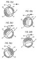
- FIG 2 illustrates the banknote insertion and extraction operations in more detail with reference to a drum 4 having two small and two large storage regions, the operations involving adding a banknote to and removing a banknote from the storage region 12.
- the suction means of the roller 16 is indicated by an arrow. This represents the point on the roller at which the suction means operates, and also indicates whether the suction means is providing suction (when the arrow is pointing radially inwardly) or whether the operation is reversed to provide pressure (when the arrow is pointing radially outwardly).
- Figures 2(a) to 2(e) represent the insertion operation
- Figure 3 shows a modified version of the store of Figures 1 and 2, like reference numbers representing like integers.
- a system of belts is provided for delivering banknotes in the direction of arrows I over the roller 16 to the drum 4 and for extracting the banknote in the direction of arrows E under the roller 16. Accordingly, the roller 16 rotates clockwise and the drum 4 anti-clockwise for both insertion and extraction of banknotes. Part of one of the belts around the drum periphery is shown at 18.
- FIG. 4 shows a further modification, and again like reference numbers represent like integers.
- Banknotes to be inserted on the drum are fed into an entry/exit 20 and are delivered in the direction of arrow I to the roller 16.
- the roller picks up the banknote from a belt 22 and feeds it to one of the storage regions 6, 8, 10 or 12.
- the roller 16 is moving anti-clockwise and the drum 4 clockwise.
- the drum 4 and roller 16 are rotated in the same directions to extract banknotes individually from the storage regions.
- Each banknote is picked up by the suction means in the roller 16 and fed to the belt 22, which carries the note to an intermediate store, or escrow, 24.
- This may be of a known type (see for example EP-A-0 791 211).
- Successive notes are fed from the drum 4 to a drum 26 of the escrow 24 while the drum 26 is rotated anti-clockwise.
- the movement of the drums 4 and 26 and intervening roller 16 and belts are controlled such that the leading edge of each note arrives always at the same point on the drum 26, so that a stack of banknotes is progressively built up on the drum 26.
- the stack is released from the escrow and the notes are fed as a bundle in the direction of arrow E to the entry/exit 20.
- the belt 28 feeding banknotes to the drum 26 may be formed separately from the belt 22 which receives banknotes from the drum 4, the belts 22 and 28 being selectively operated using, for example, clutches to engage rollers 30 in response to sensors, so that the banknotes reach the drum 26 at the correct position.
- inventions described above are particularly suited for storing respective denominations in the different storage compartments and for dispensing banknotes in selected combinations as change.
- one or more of the compartments may not always be required for such stored banknotes to be retrievable individually from the banknote store.
- the embodiments of Figures 3 and 4 are particularly suited for this.
- the leading edge of the banknote as it is stored on the drum 4 is always in a predetermined position, and this same edge is also the leading edge when the banknote is retrieved from the drum.
- the retrieval operation can commence at a known position with respect to the drum. It doesn't matter if the banknotes are of different sizes, and particularly different widths, because this will merely lead to their trailing edges being located at different positions as indicated at 29 in Figures 3 and 4.
- retrieval of banknotes from a multi-denominational stack can easily be accomplished, for example for the purpose of transferring the banknotes to a different store, refunding all the stacked banknotes, or refunding selected individual banknotes from the stack (the remainder possibly being sent back to the store or sent to a different store).
- the belt 18 of Figures 3 and 4. together with a similar belt used in the embodiment of Figure 1, may be used for both holding the stacks in position against the biasing means as well as imparting rotational movement to the drum 26.
- Figure 5 shows a banknote handling apparatus incorporating a banknote store which operates on a similar principle to that of Figure 4.
- the apparatus is intended for installation at a till, and is arranged to receive individual banknotes, test them for denomination and authenticity, store them in the banknote store 2 and refund selected denominations as a bundle.
- the apparatus comprises a main body 30 which is intended for installation in an aperture in a cashiers desktop 32.
- the banknote store 2 is mounted in a removable housing 34 containing the drum 4 and the surrounding belt 18.
- the housing 34 can be accessed by using a key 36 to unlock a lid 38.
- the housing 34 can then be removed using a handle 40, leaving behind the means for feeding banknotes to and removing banknotes from the banknote store 2, including the roller 16.
- the banknotes are still retained in the drum 4 by the belt 18.
- banknotes are inserted into an inlet/outlet 42 in the upper surface of the main body 30.
- the banknotes are individually fed by belts between sensors S1 and S2 to permit their validation.
- a display 43 provides information in dependence on the results of the validation. If the banknotes are found to be invalid, they are refunded by reversing the movement of the belts to present them at the inlet/outlet 42. Otherwise, they are fed to an appropriate one of the storage regions of the banknote store 2.
- Various amounts of money can be refunded by sending selected denominations from the store 2 to the escrow 24, from which they are refunded as a bundle to the inlet/outlet 42.
- the main body 30 has a subsidiary section 44, in which the banknote store 2 is housed. By unlocking another lock 45, the subsidiary section 44 can be pivoted upwardly about a hinge 46 for easy access to the banknote path from the inlet/outlet 42 to the roller 16, and from the roller 16 to the escrow 24.
- the housing 34 has an aperture for receiving the roller 16, this aperture being automatically closed by means of biased shutter elements 48 when the housing 34 is removed.
- Banknote stores according to the present invention can be designed for a variety of different applications.
- the banknote store of Figure 5 has three relatively small storage regions, 6, 8 and 10, each arranged to store banknotes of a respective single denomination, so that these banknotes can be used for providing change.
- these banknotes are of small denominations.
- the fourth storage region, 12, is substantially larger and is used for storing all other denominations, in addition to the same denominations stored in the other regions 6, 8 and 10 when those regions contain a sufficient number of banknotes.
- the banknote store 2 therefore functions as a main cashbox storing banknotes which are removed when the banknotes are to be collected, together with a store for banknotes payable as change.
- the drum may be provided with (a) a main storage region 8 serving as the cashbox, (b) a first small storage region 6 serving as an escrow, and (c) a second small storage region 10 for receiving banknotes deemed to be counterfeit, all the regions being arranged for storing multiple denominations.
- any banknotes for the current transaction are successively fed to the storage region 6.
- these banknotes can be removed and either refunded to a customer, if for example the transaction is cancelled, or transferred to the main storage region 8.
- Means may be provided for removing the notes from the region 6 as a single bundle, for example by stripping them from the drum 4.
- the region 6 can be arranged to receive individual banknotes of selected denominations from a separate store, and then refund them in a bundle as change.
- a banknote store may incorporate storage regions which collectively perform any one or more of the following functions:
- the relative sizes of the storage regions would be designed so that they are suited for their intended functions.
- the drum in a banknote store is preferably capable of rotating continuously in either a single direction or in opposite directions as appropriate for receiving and/or discharging banknotes, it would be possible alternatively to use a partial rotation, i.e. a reciprocating or pivoting movement.
- the illustrated embodiments each have a single region at which banknotes can be added to and extracted from the store. Alternatively there may be separate regions for addition and extraction, respectively, and/or multiple regions for one or both functions.
- the illustrated embodiments each have a plurality of storage regions, some of the advantages of the invention (for example the provision of a large-capacity store with a small-size deposition system) can be achieved in an embodiment arranged to have only a single stack.
- This could be the main cash store, preferably multi-denominational, so no means for removing banknotes from the stack would be required.
- the store could be pre-loaded with banknotes and used for dispensing only, in which case no depositing means is required.
Abstract
Description
- This invention relates to stores for value sheets such as banknotes, cheques or the like (herein referred to collectively as "banknotes").
- In many apparatuses it is desirable to provide multiple banknote stores for various reasons. For example, in a banknote handling apparatus it is desirable to have a cashbox store, an escrow and in some circumstances a store for forgeries. It has also been proposed to provide a banknote apparatus in which banknotes of different denominations can be individually dispensed, in which case it is desirable to have respective stores for the different denominations.
- However, providing multiple stores each with their own mechanisms for delivering and, possibly, removing banknotes results in a large, complicated and expensive apparatus, especially as many stores require pistons with a large stroke for insertion of banknotes.
- It is known (see for example EP-A-0 791 211, incorporated herein by reference) to provide an escrow store in the form of a drum having a belt around it, the arrangement being such that a stack can be gradually built up on the drum, the stack being held in place by the belt, by feeding banknotes in succession to the drum in synchronism with the rotation of the drum. However, this arrangement allows only a relatively small number of bills to be stacked, thereby limiting its usefulness.
- Aspects of the present invention are set out in the accompanying claims.
- According to a further, independent aspect of the invention, banknotes are stored in one, or preferably a plurality of, storage regions displaced around the axis of rotation of a common structure. The structure can be rotated to bring any selected access region into proximity to means for delivering and/or removing banknotes to/from the structure. Accordingly, multiple banknote storage regions can be provided in a compact manner, and can share a common delivery and/or removal means. Each stack extends inwardly, generally towards the axis of rotation (though not necessarily exactly radially), and is arranged so that the location of the top of the stack does not alter as the stack grows and/or shrinks; thus, the overall size of the structure does not change, and a large number of banknotes can be stored.
- In the preferred embodiment, banknotes are individually removable from each region so they can, for example, be dispensed as change. To facilitate individual removal, the removal means may incorporate a suction means which is arranged to draw the uppermost banknote from a stack thereof.
- Arrangements embodying the invention will now be described by way of example with reference to the accompanying drawings, in which:
- Figure 1 schematically shows a first banknote store in accordance with the invention;
- Figures 2a to 2j schematically demonstrate how banknotes can be delivered to and removed from a store in accordance with the invention;
- Figure 3 schematically illustrates a further banknote store in accordance with the invention;
- Figure 4 illustrates yet another banknote store in accordance with the invention;
- Figure 5 shows a banknote handling apparatus incorporating a banknote store which operates using the principles of the present invention; and
- Figure 6 illustrates a different configuration of storage regions in a drum of a banknote store.
-
- Referring to Figure 1, a
banknote store 2 comprises astorage drum 4 having, in this case, four storage regions orcompartments - In order to provide room for more storage regions around the circumference of the drum, the banknotes are preferably stored with their longer dimension parallel to the
axis 14 of rotation of the drum. - Biasing means (not shown in Figure 1) are provided for biasing the stacks of banknotes radially outwardly, the stacks being held in position by at least one belt (not shown in Figure 1), preferably an endless belt, extending around the periphery of the drum. The belt does not extend around the complete periphery; instead, there is an insertion/removal region, including the point A, which is left open to permit banknotes to be added to or removed from the store. The insertion and extraction of banknotes is achieved using a
roller 16. - In operation, if a banknote is to be added to a storage region of the drum, the banknote is fed in the direction of arrow I while the
roller 16 is rotated in an anti-clockwise direction and thedrum 4 in a clockwise direction. The feeding of the banknote is synchronised with the position of thedrum 4, such that the leading edge of the banknote reaches the point A at the same time as the leading edge of a selected storage region (forexample storage region 10 as shown in Figure 1), the selection being based on the denomination of the banknote. Continued rotation of thedrum 4 and theroller 16 will result in the banknote being progressively rolled on to the top of the stack of banknotes in the storage region, thus avoiding the need for a pusher plate to transfer the banknotes to the stack. - Removal of a banknote is accomplished by reversing the directions of rotation of the
drum 4 and theroller 16. Preferably, theroller 16 is provided with suction means (not shown in Figure 1), to peel off the uppermost banknote in one of the storage regions, the suction means thereafter releasing the banknote so that it can travel away from thestore 2 in the direction of arrow E. - Figure 2 illustrates the banknote insertion and extraction operations in more detail with reference to a
drum 4 having two small and two large storage regions, the operations involving adding a banknote to and removing a banknote from thestorage region 12. Although the drawing diagrammatically illustrates only a few banknotes in each storage region for purposes of clarity, in practice each storage region (or at least the two larger ones) can hold several hundred banknotes. The suction means of theroller 16 is indicated by an arrow. This represents the point on the roller at which the suction means operates, and also indicates whether the suction means is providing suction (when the arrow is pointing radially inwardly) or whether the operation is reversed to provide pressure (when the arrow is pointing radially outwardly). Figures 2(a) to 2(e) represent the insertion operation, and Figures 2(f) to 2(j) the extraction operation. - Figure 3 shows a modified version of the store of Figures 1 and 2, like reference numbers representing like integers. In this case, a system of belts is provided for delivering banknotes in the direction of arrows I over the
roller 16 to thedrum 4 and for extracting the banknote in the direction of arrows E under theroller 16. Accordingly, theroller 16 rotates clockwise and thedrum 4 anti-clockwise for both insertion and extraction of banknotes. Part of one of the belts around the drum periphery is shown at 18. - Figure 4 shows a further modification, and again like reference numbers represent like integers. Banknotes to be inserted on the drum are fed into an entry/
exit 20 and are delivered in the direction of arrow I to theroller 16. Using suction, the roller picks up the banknote from abelt 22 and feeds it to one of thestorage regions roller 16 is moving anti-clockwise and thedrum 4 clockwise. - The
drum 4 androller 16 are rotated in the same directions to extract banknotes individually from the storage regions. Each banknote is picked up by the suction means in theroller 16 and fed to thebelt 22, which carries the note to an intermediate store, or escrow, 24. This may be of a known type (see for example EP-A-0 791 211). Successive notes are fed from thedrum 4 to adrum 26 of theescrow 24 while thedrum 26 is rotated anti-clockwise. The movement of thedrums roller 16 and belts are controlled such that the leading edge of each note arrives always at the same point on thedrum 26, so that a stack of banknotes is progressively built up on thedrum 26. Then, by rotating thedrum 26 clockwise, the stack is released from the escrow and the notes are fed as a bundle in the direction of arrow E to the entry/exit 20. - The operation of the arrangement of Figure 4 is such that, if successive banknotes from the
store 10 are fed to theescrow 24, the leading edges of those banknotes, which will be at point L when the banknotes are stored in thedrum 4, will always arrive at the same position, for example L1 on thedrum 26 of the escrow. Preferably, this also applies to the banknotes stored in the other storage regions, 6, 8 and 12, so that a single bundle of banknotes formed on thedrum 26 can be derived from a plurality of the storage regions. - To facilitate this synchronisation, the
belt 28 feeding banknotes to thedrum 26 may be formed separately from thebelt 22 which receives banknotes from thedrum 4, thebelts rollers 30 in response to sensors, so that the banknotes reach thedrum 26 at the correct position. - The embodiments described above are particularly suited for storing respective denominations in the different storage compartments and for dispensing banknotes in selected combinations as change. However, it would be possible for one or more of the compartments to store banknotes of multiple denominations. It may not always be required for such stored banknotes to be retrievable individually from the banknote store. However, if it is desired to provide for individual retrieval of banknotes stored in a multi-denominational stack, then the embodiments of Figures 3 and 4 are particularly suited for this. In Figures 3 and 4, the leading edge of the banknote as it is stored on the
drum 4 is always in a predetermined position, and this same edge is also the leading edge when the banknote is retrieved from the drum. Accordingly, the retrieval operation can commence at a known position with respect to the drum. It doesn't matter if the banknotes are of different sizes, and particularly different widths, because this will merely lead to their trailing edges being located at different positions as indicated at 29 in Figures 3 and 4. - Accordingly, retrieval of banknotes from a multi-denominational stack can easily be accomplished, for example for the purpose of transferring the banknotes to a different store, refunding all the stacked banknotes, or refunding selected individual banknotes from the stack (the remainder possibly being sent back to the store or sent to a different store).
- The
belt 18 of Figures 3 and 4. together with a similar belt used in the embodiment of Figure 1, may be used for both holding the stacks in position against the biasing means as well as imparting rotational movement to thedrum 26. - Figure 5 shows a banknote handling apparatus incorporating a banknote store which operates on a similar principle to that of Figure 4. The apparatus is intended for installation at a till, and is arranged to receive individual banknotes, test them for denomination and authenticity, store them in the
banknote store 2 and refund selected denominations as a bundle. - The apparatus comprises a
main body 30 which is intended for installation in an aperture in acashiers desktop 32. Thebanknote store 2 is mounted in aremovable housing 34 containing thedrum 4 and the surroundingbelt 18. Thehousing 34 can be accessed by using a key 36 to unlock alid 38. Thehousing 34 can then be removed using ahandle 40, leaving behind the means for feeding banknotes to and removing banknotes from thebanknote store 2, including theroller 16. The banknotes are still retained in thedrum 4 by thebelt 18. - In operation, banknotes are inserted into an inlet/
outlet 42 in the upper surface of themain body 30. The banknotes are individually fed by belts between sensors S1 and S2 to permit their validation. Adisplay 43 provides information in dependence on the results of the validation. If the banknotes are found to be invalid, they are refunded by reversing the movement of the belts to present them at the inlet/outlet 42. Otherwise, they are fed to an appropriate one of the storage regions of thebanknote store 2. Various amounts of money can be refunded by sending selected denominations from thestore 2 to theescrow 24, from which they are refunded as a bundle to the inlet/outlet 42. - The
main body 30 has asubsidiary section 44, in which thebanknote store 2 is housed. By unlocking anotherlock 45, thesubsidiary section 44 can be pivoted upwardly about ahinge 46 for easy access to the banknote path from the inlet/outlet 42 to theroller 16, and from theroller 16 to theescrow 24. - The
housing 34 has an aperture for receiving theroller 16, this aperture being automatically closed by means ofbiased shutter elements 48 when thehousing 34 is removed. - Banknote stores according to the present invention can be designed for a variety of different applications. For example, the banknote store of Figure 5 has three relatively small storage regions, 6, 8 and 10, each arranged to store banknotes of a respective single denomination, so that these banknotes can be used for providing change. Preferably, these banknotes are of small denominations. The fourth storage region, 12, is substantially larger and is used for storing all other denominations, in addition to the same denominations stored in the
other regions banknote store 2 therefore functions as a main cashbox storing banknotes which are removed when the banknotes are to be collected, together with a store for banknotes payable as change. - In an alternative arrangement, for which a suitable drum structure is shown in Figure 6, the drum may be provided with (a) a
main storage region 8 serving as the cashbox, (b) a firstsmall storage region 6 serving as an escrow, and (c) a secondsmall storage region 10 for receiving banknotes deemed to be counterfeit, all the regions being arranged for storing multiple denominations. In operation, any banknotes for the current transaction are successively fed to thestorage region 6. At the end of the transaction. these banknotes can be removed and either refunded to a customer, if for example the transaction is cancelled, or transferred to themain storage region 8. Means (not shown) may be provided for removing the notes from theregion 6 as a single bundle, for example by stripping them from thedrum 4. Alternatively, or additionally, theregion 6 can be arranged to receive individual banknotes of selected denominations from a separate store, and then refund them in a bundle as change. - Any fraudulent banknotes are sent to the
storage region 10, and are collected with the banknotes in themain cashbox region 8 when the banknote apparatus is emptied. - Accordingly, a banknote store according to the present invention may incorporate storage regions which collectively perform any one or more of the following functions:
- (a) a main cashbox store for receiving banknotes which are preferably of a plurality of denominations, and probably non-refundable;
- (b) a single-denomination store from which banknotes can be individually refunded;
- (c) an intermediate store for temporarily storing notes received during a transaction, the notes being removable either collectively or individually;
- (d) an temporary store for accumulating notes which are retrieved from storage individually, so that the notes can be accumulated as a bundle before being dispensed;
- (e) a store for counterfeit banknotes.
-
- The relative sizes of the storage regions would be designed so that they are suited for their intended functions.
- Clearly, if none of the storage regions is intended for individual retrieval of banknotes, then the retrieval mechanism, for example the suction arrangements described above, can be omitted.
- Although the drum in a banknote store according to the present invention is preferably capable of rotating continuously in either a single direction or in opposite directions as appropriate for receiving and/or discharging banknotes, it would be possible alternatively to use a partial rotation, i.e. a reciprocating or pivoting movement.
- The illustrated embodiments each have a single region at which banknotes can be added to and extracted from the store. Alternatively there may be separate regions for addition and extraction, respectively, and/or multiple regions for one or both functions.
- Although the illustrated embodiments each have a plurality of storage regions, some of the advantages of the invention (for example the provision of a large-capacity store with a small-size deposition system) can be achieved in an embodiment arranged to have only a single stack. This could be the main cash store, preferably multi-denominational, so no means for removing banknotes from the stack would be required. Alternatively, the store could be pre-loaded with banknotes and used for dispensing only, in which case no depositing means is required.
Claims (18)
- A banknote store comprising a rotatable structure having at least one banknote-storing region capable of storing a stack of banknotes, the store having means for rotating the structure so as to bring the stack into proximity to a means for delivering a banknote to and/or removing a banknote from the stack, and the stack being arranged so that a greater number of banknotes in the stack results in the stack extending further inwardly towards the axis of rotation of the structure.
- A banknote store comprising a rotatable structure having a plurality of banknote-storing regions each capable of storing a stack of banknotes, the stacks being displaced around the axis of rotation and the store having means for rotating the structure so as to bring a selected stack into proximity to a means for delivering a banknote to and/or removing a banknote from the stack.
- A banknote store as claimed in claim 1 or claim 2, arranged such that banknotes are deposited on, or removed from, a stack progressively as the structure rotates.
- A banknote store as claimed in any preceding claim, including a belt means extending around the periphery of the structure and arranged to retain the stack in each banknote-storing region.
- A banknote store as claimed in claim 4, wherein the structure is arranged to be rotated by movement of the belt means.
- A banknote store as claimed in any preceding claim, wherein the delivering and/or removing means is a delivering means.
- A banknote store as claimed in any preceding claim, wherein the delivering and/or removing means is a removing means.
- A banknote store as claimed in any preceding claim, wherein the delivering and/or removing means comprises means for effecting both delivery of banknotes to the structure and removal of banknotes therefrom.
- A banknote store as claimed in claim 7 or claim 8, wherein the removing means is operable to remove banknotes individually from each banknote-storing region.
- A banknote store as claimed in claim 9, wherein the removing means comprises suction means.
- A banknote store as claimed in any preceding claim, having a plurality of banknote-storing regions arranged for storing respective denominations.
- A banknote store as claimed in any preceding claim, including a banknote-storing region arranged for storing multiple denominations.
- A banknote store as claimed in any preceding claim, including a banknote-storing region which is a temporary store for successively receiving banknotes deposited during a transaction.
- A banknote store as claimed in any preceding claim, including a banknote-storing region which is a temporary store for successively receiving stored banknotes for dispensing as a bundle.
- A banknote store as claimed in any preceding claim, including a banknote-storing region which is arranged for receiving banknotes deemed to be forgeries.
- A banknote store as claimed in any preceding claim, wherein each banknote-storing region is arranged to store banknotes with their longer dimension substantially parallel to the axis of rotation.
- A banknote handling apparatus comprising a banknote validator and a banknote store as claimed in any preceding claim, the store being operable to receive banknotes validated by the banknote validator.
- A banknote handling apparatus as claimed in claim 17, wherein the banknote store is removable from the apparatus in such a manner that any banknotes stored in the banknote-storing regions are retained by the store.
Priority Applications (2)
| Application Number | Priority Date | Filing Date | Title |
|---|---|---|---|
| EP00311730A EP1220167A1 (en) | 2000-12-28 | 2000-12-28 | Banknote store |
| US10/032,784 US6786479B2 (en) | 2000-12-28 | 2001-12-26 | Banknote store with a rotatable structure having banknote-storing regions |
Applications Claiming Priority (1)
| Application Number | Priority Date | Filing Date | Title |
|---|---|---|---|
| EP00311730A EP1220167A1 (en) | 2000-12-28 | 2000-12-28 | Banknote store |
Publications (1)
| Publication Number | Publication Date |
|---|---|
| EP1220167A1 true EP1220167A1 (en) | 2002-07-03 |
Family
ID=8173492
Family Applications (1)
| Application Number | Title | Priority Date | Filing Date |
|---|---|---|---|
| EP00311730A Withdrawn EP1220167A1 (en) | 2000-12-28 | 2000-12-28 | Banknote store |
Country Status (2)
| Country | Link |
|---|---|
| US (1) | US6786479B2 (en) |
| EP (1) | EP1220167A1 (en) |
Cited By (4)
| Publication number | Priority date | Publication date | Assignee | Title |
|---|---|---|---|---|
| WO2004077365A2 (en) * | 2003-02-28 | 2004-09-10 | Innovative Technology Ltd | Improvements relating to the handling and dispensing of flexible sheets |
| DE102005036304A1 (en) * | 2005-08-02 | 2007-02-08 | Giesecke & Devrient Gmbh | Sheet type article e.g. bank note, processing device, has temporary storage unit provided in conveyance channel, where unit has barrel with variable diameter for storing conveyed articles on ring-shaped circumference |
| WO2008074288A1 (en) * | 2006-12-21 | 2008-06-26 | Adp Gauselmann Gmbh | Device for accepting and issuing paper-type payment means |
| WO2008074255A1 (en) * | 2006-12-19 | 2008-06-26 | Shandong New Beiyang Information Technology Co., Ltd. | A recording medium accumulating device and method |
Families Citing this family (4)
| Publication number | Priority date | Publication date | Assignee | Title |
|---|---|---|---|---|
| US7066335B2 (en) * | 2001-12-19 | 2006-06-27 | Pretech As | Apparatus for receiving and distributing cash |
| EP1443344A1 (en) * | 2003-01-29 | 2004-08-04 | Heptagon Oy | Manufacturing micro-structured elements |
| CA2539866A1 (en) * | 2006-03-16 | 2007-09-16 | Crane Canada Co. | Flat banknote dispenser |
| DE102007020753A1 (en) * | 2007-05-03 | 2008-11-06 | Giesecke & Devrient Gmbh | Device for accepting and issuing value documents |
Citations (6)
| Publication number | Priority date | Publication date | Assignee | Title |
|---|---|---|---|---|
| US3899103A (en) * | 1971-10-20 | 1975-08-12 | Glory Kogyo Kk | Money container setting circuit in an automatic money dispenser |
| FR2356588A1 (en) * | 1976-06-30 | 1978-01-27 | Rech Tech Et Indles | Sheet extraction system from bundle - has rotary suction rollers travelling along circular path past bundle magazine |
| EP0151808A2 (en) * | 1984-01-03 | 1985-08-21 | Atalla Corporation | Improved currency-dispensing method and apparatus |
| DE4202664A1 (en) * | 1992-01-28 | 1993-07-29 | Bally Wulff Automaten Gmbh | Banknote handling and sorting system for e.g. for games machine, change machine - has notes passed through checking stages and transferred to one of number of magazines. |
| EP0791211A1 (en) | 1994-11-09 | 1997-08-27 | Mars Incorporated | Apparatus for handling sheets |
| EP0892372A1 (en) * | 1996-11-28 | 1999-01-20 | Jaime Sallen Rosello | Automatic banknote handling system |
Family Cites Families (18)
| Publication number | Priority date | Publication date | Assignee | Title |
|---|---|---|---|---|
| CH558575A (en) * | 1973-05-24 | 1975-01-31 | Sodeco Compteurs De Geneve | MEMORY DEVICE FOR SHORT-TERM STORAGE OF PAPER SHEETS, IN PARTICULAR BANKNOTES. |
| IT992087B (en) * | 1973-07-11 | 1975-09-10 | Gd Spa | DEVICE FOR ACCUMULATION AND ALI MENTATION OF TRAITS OF MATERIAL IN THE SHEET |
| GB1485041A (en) * | 1974-01-23 | 1977-09-08 | Crosfield Business Mach Ltd | Sheet feeding mechanisms |
| US4106667A (en) * | 1976-12-20 | 1978-08-15 | International Business Machines Corporation | Apparatus and method for conducting financial transactions |
| US4515288A (en) * | 1982-12-01 | 1985-05-07 | Atalla Corporation | Currency-dispensing method and apparatus |
| US4547113A (en) * | 1984-06-19 | 1985-10-15 | The Procter & Gamble Company | Continuous motion spiral stacker |
| US4710351A (en) * | 1984-10-04 | 1987-12-01 | Miles Laboratories, Inc. | Automated handling system |
| US5020787A (en) * | 1988-05-06 | 1991-06-04 | Laurel Bank Machines Co., Ltd. | Bill processing apparatus |
| JP2667739B2 (en) * | 1990-08-16 | 1997-10-27 | 沖電気工業株式会社 | Banknote automatic deposit and withdrawal device |
| CH688141A5 (en) * | 1994-05-20 | 1997-05-30 | Ferag Ag | Apparatus for processing printing products. |
| GB9426341D0 (en) * | 1994-12-29 | 1995-03-01 | At & T Global Inf Solution | A transaction terminal |
| DE19540964C1 (en) * | 1995-11-03 | 1996-10-24 | Licentia Gmbh | Letter stacker device |
| JP3284040B2 (en) * | 1996-02-29 | 2002-05-20 | ローレルバンクマシン株式会社 | Banknote handling machine |
| NL1007942C2 (en) * | 1997-12-31 | 1999-07-01 | Hadewe Bv | In-line processing of flat objects. |
| DE19811698C2 (en) * | 1998-03-18 | 2001-06-21 | Bdt Buero Datentech Gmbh | Device for collecting sheets of a recording medium in bundles |
| US6264102B1 (en) * | 1998-11-23 | 2001-07-24 | Diebold, Incorporated | Automated transaction machine with note storage reel |
| WO2000052649A1 (en) | 1999-03-03 | 2000-09-08 | Cashcode Company Inc. | Combination bill accepting and bill dispensing device |
| JP4051178B2 (en) * | 2000-09-18 | 2008-02-20 | 日立オムロンターミナルソリューションズ株式会社 | Paper sheet handling equipment |
-
2000
- 2000-12-28 EP EP00311730A patent/EP1220167A1/en not_active Withdrawn
-
2001
- 2001-12-26 US US10/032,784 patent/US6786479B2/en not_active Expired - Fee Related
Patent Citations (6)
| Publication number | Priority date | Publication date | Assignee | Title |
|---|---|---|---|---|
| US3899103A (en) * | 1971-10-20 | 1975-08-12 | Glory Kogyo Kk | Money container setting circuit in an automatic money dispenser |
| FR2356588A1 (en) * | 1976-06-30 | 1978-01-27 | Rech Tech Et Indles | Sheet extraction system from bundle - has rotary suction rollers travelling along circular path past bundle magazine |
| EP0151808A2 (en) * | 1984-01-03 | 1985-08-21 | Atalla Corporation | Improved currency-dispensing method and apparatus |
| DE4202664A1 (en) * | 1992-01-28 | 1993-07-29 | Bally Wulff Automaten Gmbh | Banknote handling and sorting system for e.g. for games machine, change machine - has notes passed through checking stages and transferred to one of number of magazines. |
| EP0791211A1 (en) | 1994-11-09 | 1997-08-27 | Mars Incorporated | Apparatus for handling sheets |
| EP0892372A1 (en) * | 1996-11-28 | 1999-01-20 | Jaime Sallen Rosello | Automatic banknote handling system |
Cited By (11)
| Publication number | Priority date | Publication date | Assignee | Title |
|---|---|---|---|---|
| WO2004077365A2 (en) * | 2003-02-28 | 2004-09-10 | Innovative Technology Ltd | Improvements relating to the handling and dispensing of flexible sheets |
| WO2004077365A3 (en) * | 2003-02-28 | 2005-02-10 | Innovative Technology Ltd | Improvements relating to the handling and dispensing of flexible sheets |
| DE102005036304A1 (en) * | 2005-08-02 | 2007-02-08 | Giesecke & Devrient Gmbh | Sheet type article e.g. bank note, processing device, has temporary storage unit provided in conveyance channel, where unit has barrel with variable diameter for storing conveyed articles on ring-shaped circumference |
| DE102005036304B4 (en) * | 2005-08-02 | 2014-01-23 | Giesecke & Devrient Gmbh | Device for processing sheet material |
| WO2008074255A1 (en) * | 2006-12-19 | 2008-06-26 | Shandong New Beiyang Information Technology Co., Ltd. | A recording medium accumulating device and method |
| US8177230B2 (en) | 2006-12-19 | 2012-05-15 | Shandong New Beiyang Information Technology Co., Ltd. | Recording medium accumulating device and method |
| CN101205030B (en) * | 2006-12-19 | 2012-10-17 | 山东新北洋信息技术股份有限公司 | Recording medium receiving device and method |
| WO2008074288A1 (en) * | 2006-12-21 | 2008-06-26 | Adp Gauselmann Gmbh | Device for accepting and issuing paper-type payment means |
| US7654442B2 (en) | 2006-12-21 | 2010-02-02 | Adp Gauselmann Gmbh | Device for the intake and output of paper currencies |
| RU2452031C2 (en) * | 2006-12-21 | 2012-05-27 | Адп Гаузельманн Гмбх | Device for receiving and issuing banknotes |
| US8256603B2 (en) | 2006-12-21 | 2012-09-04 | Adp Gauselmann Gmbh | Device for intake and output of paper currency and method therefore |
Also Published As
| Publication number | Publication date |
|---|---|
| US20020093133A1 (en) | 2002-07-18 |
| US6786479B2 (en) | 2004-09-07 |
Similar Documents
| Publication | Publication Date | Title |
|---|---|---|
| JP3977982B2 (en) | Banknote storage and release box and banknote deposit and withdrawal machine | |
| KR100351172B1 (en) | Automated teller machine | |
| JP4292012B2 (en) | Banknote deposit and withdrawal device | |
| KR880000894A (en) | Transaction processing unit | |
| US6786479B2 (en) | Banknote store with a rotatable structure having banknote-storing regions | |
| JP4047424B2 (en) | Automatic cash machine | |
| JP3202554B2 (en) | Bill receiving / dispensing device | |
| JP4845905B2 (en) | Banknote deposit and withdrawal machine | |
| JP6907708B2 (en) | Medium discharge device and medium processing device | |
| JP2004510274A (en) | Arrangement of banknote handling machines for inserting and removing banknotes | |
| JPH0554223A (en) | Circulation type paper currency receiving and paying device | |
| JP2001266211A (en) | Cash processing device | |
| JP2906796B2 (en) | Paper storage box | |
| JP4374724B2 (en) | Banknote handling equipment | |
| JPS6242296A (en) | Paper money handler | |
| JP2007087403A (en) | Bank bill storage/discharge cabinet | |
| JP2006190333A (en) | Paper currency dispenser | |
| JPH1116023A (en) | Automatic transaction device and temporary pool device | |
| JPH0511236Y2 (en) | ||
| JPS624143A (en) | Cash disposing device at cage | |
| JP2669709B2 (en) | Intermediate collection control processing device of deposit / withdrawal machine | |
| JP3575956B2 (en) | Coin processing device and automatic transaction device | |
| KR20010039833A (en) | Bill recycle machine | |
| JPH036556B2 (en) | ||
| JPH0452996A (en) | Automatic paper money handling device |
Legal Events
| Date | Code | Title | Description |
|---|---|---|---|
| PUAI | Public reference made under article 153(3) epc to a published international application that has entered the european phase |
Free format text: ORIGINAL CODE: 0009012 |
|
| AK | Designated contracting states |
Kind code of ref document: A1 Designated state(s): AT BE CH CY DE DK ES FI FR GB GR IE IT LI LU MC NL PT SE TR |
|
| AX | Request for extension of the european patent |
Free format text: AL;LT;LV;MK;RO;SI |
|
| 17P | Request for examination filed |
Effective date: 20030102 |
|
| AKX | Designation fees paid |
Designated state(s): DE ES FR GB IT |
|
| RAP1 | Party data changed (applicant data changed or rights of an application transferred) |
Owner name: MEI, INC. |
|
| 111Z | Information provided on other rights and legal means of execution |
Free format text: DEESFRGBIT Effective date: 20061103 |
|
| 111Z | Information provided on other rights and legal means of execution |
Free format text: DE ES FR GB IT Effective date: 20070802 |
|
| STAA | Information on the status of an ep patent application or granted ep patent |
Free format text: STATUS: THE APPLICATION IS DEEMED TO BE WITHDRAWN |
|
| 18D | Application deemed to be withdrawn |
Effective date: 20100701 |
|
| R11X | Information provided on other rights and legal means of execution (corrected) |
Free format text: DE ES FR GB IT Effective date: 20070802 |