EP1220003B1 - Optical architecture for observation telescope - Google Patents
Optical architecture for observation telescope Download PDFInfo
- Publication number
- EP1220003B1 EP1220003B1 EP01402992A EP01402992A EP1220003B1 EP 1220003 B1 EP1220003 B1 EP 1220003B1 EP 01402992 A EP01402992 A EP 01402992A EP 01402992 A EP01402992 A EP 01402992A EP 1220003 B1 EP1220003 B1 EP 1220003B1
- Authority
- EP
- European Patent Office
- Prior art keywords
- mirror
- correction plate
- path
- reflected
- convergent
- Prior art date
- Legal status (The legal status is an assumption and is not a legal conclusion. Google has not performed a legal analysis and makes no representation as to the accuracy of the status listed.)
- Expired - Lifetime
Links
Images
Classifications
-
- G—PHYSICS
- G02—OPTICS
- G02B—OPTICAL ELEMENTS, SYSTEMS OR APPARATUS
- G02B17/00—Systems with reflecting surfaces, with or without refracting elements
- G02B17/08—Catadioptric systems
- G02B17/0852—Catadioptric systems having a field corrector only
-
- G—PHYSICS
- G02—OPTICS
- G02B—OPTICAL ELEMENTS, SYSTEMS OR APPARATUS
- G02B17/00—Systems with reflecting surfaces, with or without refracting elements
- G02B17/08—Catadioptric systems
-
- G—PHYSICS
- G02—OPTICS
- G02B—OPTICAL ELEMENTS, SYSTEMS OR APPARATUS
- G02B23/00—Telescopes, e.g. binoculars; Periscopes; Instruments for viewing the inside of hollow bodies; Viewfinders; Optical aiming or sighting devices
- G02B23/02—Telescopes, e.g. binoculars; Periscopes; Instruments for viewing the inside of hollow bodies; Viewfinders; Optical aiming or sighting devices involving prisms or mirrors
- G02B23/06—Telescopes, e.g. binoculars; Periscopes; Instruments for viewing the inside of hollow bodies; Viewfinders; Optical aiming or sighting devices involving prisms or mirrors having a focussing action, e.g. parabolic mirror
Definitions
- the invention relates to an optical architecture of an observation telescope wide field and in particular a telescope intended to be installed aboard a vehicle.
- This vehicle is for example a space satellite exploiting the telescope to terrestrial observation purposes, as provided for example by the program SPOT observation.
- anastigmatic telescopes with three mirrors classically designated by the acronym TMA (for "three mirrors anastigmat”).
- TMA for "three mirrors anastigmat”
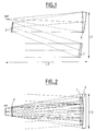
- known and appropriate optical architecture of anastigmate telescope with three mirrors is illustrated in Figures 1 and 2.
- This telescope has a first mirror 1, aspheric, concave and cut off-axis, that is to say without symmetry of revolution, which reflects the beam so that it converges slightly to a second mirror 2, as seen in Figures 1 and 2.
- This mirror 2 is aspherical, convex and cut off-axis, unless the pupil of the telescope is located at its level, it is then obtained at from a deformed form of sphere.
- the beam it receives is returned under the shape of a divergent beam, towards a third mirror 3 as shown also the two figures mentioned above.
- This mirror 3 is aspheric, concave and cut off axis. It receives the divergent beam reflected by the mirror 2 which it focuses on level of an off-axis PF focal plane.
- the set formed by the three mirrors 1, 2 and 3 constitutes an anastigmatic optical imaging system, in which the image field is misaligned.
- Such a system is bulky with, for example, dimensions L1, L2 and L3, as illustrated in FIGS. 1 and 2, which are 550 mm, 900 mm and 400 mm, respectively, for a pupil telescope of 160 mm and focal length of 610 mm.
- Such a TMA telescope has several disadvantages, it involves the realization at least two concave aspheric mirrors, cut off the axis, which are expensive, since they have an elongated shape and are long and delicate to make.
- the set obtained is heavy which is a certain disadvantage for a piece of equipment intended to be embedded in a space satellite.
- the optical architecture defined for the telescope is sensitive to eccentricity.
- the document US5907442 describes an optical architecture of an observation telescope with a concave and off-axis mirror and a dioptric and achromatic aperture corrector.
- GB1322333 discloses a telescope with a concave mirror and two dioptric correctors.
- the invention therefore proposes an optical observation telescope architecture and in particular a large-field telescope architecture.
- a architecture is advantageously designed to be embedded in a vehicle and in particular aboard a space satellite for terrestrial zonal observation purposes.
- the pupil is placed on the face of the opening corrector which receives the the convergent beam (s) reflected by the mirror.
- the opening corrector and the field corrector are correctors achromatic, without power or almost without power.
- the opening corrector and the field corrector are respectively each consisting of lenses of at least two different types of glass.
- the choice of the glasses indices of at least one of the correctors can be exploited to take into account the variations caused by the temperature.
- a refocusing mechanism acting on the lenses of the field corrector acting on the lenses of the field corrector.
- an auxiliary intervening at the beam level such as a spectral sparkler, with dichroic prisms and divolis, allowing to share it spectrally, an image derotator, or a splitter blade for dividing the beam to obtain images in different focal planes.
- FIGS. 1 and 2 respectively correspond to a view along a YZ plane and a view along an XZ plane of the TMA telescope, known, succinctly mentioned above.
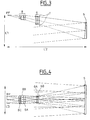
- FIGS. 3 and 4 respectively correspond to a view along a YZ plane and a view along an XZ plane of the telescope, according to the invention.
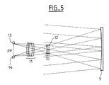
- FIG. 5 is a view relating to an alternative embodiment of the telescope according to the invention for stereo application.
- FIGS. 4 The optical telescope observation architecture illustrated in FIGS. 4 is intended to be substituted for that shown in Figures 1 and 2.
- the telescope according to the invention comprises a first mirror 5, aspheric or possibly spherical, concave and off-axis that reflects from convergent way the beam constituted by the radiation that it receives from a zone he observes.
- the second and third mirrors of a TMA telescope are here replaced by dioptric correctors that are corrected for aberrations chromatic.
- an opening corrector 6, dioptric and achromatic, which is without power or almost without power, is inserted on the path of the convergent beam reflected by the mirror 5.
- This corrector consists of at least two lenses 6A, 6B, made of different types of glass, to correct the chromaticism.
- Glasses such as those referenced FK52 and LaK8 of the company SCHOTT, can for example be used.
- the pupil 7 of the telescope is preferably placed on the front face of the opening corrector 6 which receives the convergent beam reflected by the mirror 5. The presence of a central obturation is avoided by a judicious choice of the aiming direction or in other words the view.
- a field corrector 8 dioptric and achromatic, without power or almost without power, is inserted in the path of the convergent beam reflected by the mirror 5, downstream of the opening corrector 7 with respect to this mirror 5.
- field corrector 8 is also made of lenses of at least two types of glass to correct the chromaticism, three lenses 8A, 8B, 8C, supposedly constituted different types of glass, being presented in both figures 3 and 4. The choice of respective indices of the glasses can be exploited to take into account the variations caused by the temperature.
- the realized optical architecture has the advantage of allowing a easy installation of a sighting mirror. It also has the advantage to facilitate the alignment of the constituent elements of the telescope that constitute the mirror and the correctors. It allows refocalisation in a simple way, by means of a mechanism for moving the lenses of the field corrector. alignment is facilitated by the fact that the telescope has a common axis
- auxiliaries to intervene at level of the beam, depending on the intended applications and for example to associate with telescope a spectral spark gap, a derotator, a splitter blade ...
- the spectral spark gap is for example a dichroic prisms sparkler and optical dividers, or divolis, which divides a beam received by spectral domains.
- the derotator allows an image rotation for example for that the images successively obtained during a displacement and therefore in particular of a displacement in orbit, be maintained in the same direction taking into account the speed of the vehicle carrying the telescope.
- the separating blade is exploitable to share the stream it receives for example to obtain images in two different focal planes.
- the dimensions L'1, L'2 and L'3, as illustrated in FIGS. 3 and 4, which are likely to be obtained for a pupil telescope of 160 mm and focal length 610 mm, can be of, respectively, 300 mm, 800 mm and 300 mm.
- a significant reduction in the size of the telescope is therefore obtained, particularly laterally, the mass of the telescope is of course more weak than previously, the lenses implemented with the first and only mirror being much lighter than the two mirrors of the TMA telescope to which they substitute.
- Dimensional reduction and simplification of the optical architecture is inherently less parasitic light generating than that of a TMA telescope, moreover, it facilitates the realization of protection baffles against signals parasites.
- the proposed optical architecture provides a telescope that is less eccentric sensitive than a TMA telescope.
- the telescope optical architecture described above can be exploited to obtain stereoscopic images.
- the telescope then comprises a mirror 9, aspheric or possibly spherical, concave and off-axis, the shape of which close to that of an elongated ellipse, allowing two images to be taken with a determined angular separation, for example of the order of ten degrees, which is adapted to the mission to achieve.
- An opening corrector 10 and a corrector of 11 are associated with the mirror 9.
- the two correctors are correctors dioptric and achromatic lenses, each composed of lenses of at least two types of glass. These correctors are without power, at least practically, and their arrangement compared to the mirror 9 corresponds to that of the correctors 6 and 8 with respect to the mirror 5 which has been described above.
- the pupil 12 of the telescope is preferably located on the front face of the opening corrector 10 which receives the beam convergent reflected by the mirror 9, it also has an oblong shape for let two directions of sight pass simultaneously, as shown in Figure 5. Two images are simultaneously obtained by the same telescope, with the same focal point and the same types of defect for each of them, and consequently to have the same scale factor.
- the opening corrector 10, the field corrector 11 and the pupil 12 are common to both viewing directions.
- Two bars or receiving dies 13 and 14 arranged perpendicularly to the plane of FIG. 5 allow to recover the two images simultaneously obtained in the focal plane PF.
Abstract
Description
L'invention concerne une architecture optique de télescope d'observation à grand champ et en particulier un télescope destiné à être installé à bord d'un véhicule. Ce véhicule est par exemple un satellite spatial exploitant le télescope à des fins d'observation zonale terrestre, comme prévu par exemple par le programme d'observation SPOT.The invention relates to an optical architecture of an observation telescope wide field and in particular a telescope intended to be installed aboard a vehicle. This vehicle is for example a space satellite exploiting the telescope to terrestrial observation purposes, as provided for example by the program SPOT observation.
Comme il est connu, les exigences, en matière d'observation depuis un satellite, qui sont actuellement demandées, impliquent par exemple une résolution spatiale d'observation sur une zone de quelques mètres, prise au niveau d'un champ de l'ordre de quarante à soixante kilomètres. Il est par ailleurs souhaité que le télescope n'ait pas d'obturation centrale, une telle obturation étant présente, comme il est connu avec certaines architectures de télescope.As it is known, the requirements, in terms of observation since a satellite, which are currently requested, involve, for example, a resolution spatial observation over an area of a few meters, taken at a field level on the order of forty to sixty kilometers. It is also hoped that the telescope has no central obturation, such a shutter being present, as it is known with some telescope architectures.
Ces exigences en matière d'observation et d'absence d'obturation sont
susceptibles d'être respectées par les télescopes anastigmates à trois miroirs,
classiquement désignés par l'acronyme TMA (pour "three mirrors anastigmat). Une
architecture optique connue et appropriée de télescope anastigmate à trois miroirs
est illustrée sur les figures 1 et 2. Ce télescope comporte un premier miroir 1,
asphérique, concave et taillé hors axe, c'est-à-dire sans symétrie de révolution, qui
réfléchit le faisceau de manière qu'il converge légèrement vers un second miroir 2,
comme on le voit sur les figures 1 et 2. Ce miroir 2 est asphérique, convexe et taillé
hors axe, sauf si la pupille du télescope est située à son niveau, il est alors obtenu à
partir d'une forme déformée de sphère. Le faisceau qu'il reçoit est renvoyé sous la
forme d'un faisceau divergent, vers un troisième miroir 3 comme le montre
également les deux figures évoquées ci-dessus. Ce miroir 3 est asphérique, concave
et taillé hors axe. Il reçoit le faisceau divergent réfléchi par le miroir 2 qu'il focalise au
niveau d'un plan focal PF désaxé. L'ensemble formé par les trois miroirs 1, 2 et 3
constitue un système optique anastigmatique de formation d'image, dans lequel le
champ d'image est désaxé. Un tel système est encombrant avec, par exemple, des
dimensions L1, L2 et L3, telles qu'illustrées sur les figures 1 et 2, qui sont
respectivement égales à 550 mm, 900 mm et 400 mm, pour un télescope à pupille
de 160 mm et focale de 610 mm.These requirements for observation and blanking are
likely to be respected by anastigmatic telescopes with three mirrors,
classically designated by the acronym TMA (for "three mirrors anastigmat").
known and appropriate optical architecture of anastigmate telescope with three mirrors
is illustrated in Figures 1 and 2. This telescope has a first mirror 1,
aspheric, concave and cut off-axis, that is to say without symmetry of revolution, which
reflects the beam so that it converges slightly to a
Un tel télescope TMA a plusieurs inconvénients, il implique la réalisation d'au moins deux miroirs asphériques concaves, taillés hors d'axe, qui sont coûteux, dans la mesure où ils ont une forme allongé et sont longs et délicats à réaliser. L'ensemble obtenu est lourd ce qui est inconvénient certain pour un équipement destiné à être embarqué dans un satellite spatial. De plus l'architecture optique définie pour le télescope est sensible aux excentrements.Such a TMA telescope has several disadvantages, it involves the realization at least two concave aspheric mirrors, cut off the axis, which are expensive, since they have an elongated shape and are long and delicate to make. The set obtained is heavy which is a certain disadvantage for a piece of equipment intended to be embedded in a space satellite. In addition the optical architecture defined for the telescope is sensitive to eccentricity.
Le document US5907442 décrit une architecture optique de télescope d'observation avec un miroir concave et hors axe et un correcteur d'ouverture dioptrique et achromatique.The document US5907442 describes an optical architecture of an observation telescope with a concave and off-axis mirror and a dioptric and achromatic aperture corrector.
Le document GB1322333 décrit un télescope avec un miroir concave et deux correcteurs dioptriques.GB1322333 discloses a telescope with a concave mirror and two dioptric correctors.
L'invention propose donc une architecture optique de télescope d'observation et en particulier une architecture pour télescope à grand champ. Une telle architecture est avantageusement prévue pour être embarquée à bord d'un véhicule et en particulier à bord d'un satellite spatial à des fins d'observation zonale terrestre.The invention therefore proposes an optical observation telescope architecture and in particular a large-field telescope architecture. Such a architecture is advantageously designed to be embedded in a vehicle and in particular aboard a space satellite for terrestrial zonal observation purposes.
Selon une caractéristique de l'invention, cette architecture optique de télescope comporte :
- un miroir, asphérique ou éventuellement sphérique, concave et hors axe, qui réfléchit de manière convergente le faisceau constitué par le rayonnement qu'il reçoit d'une zone terrestre qu'il observe ;
- un correcteur d'ouverture, dioptrique et achromatique, inséré sur le trajet du faisceau convergent réfléchi par le miroir ;
- un correcteur de champ, dioptrique et achromatique, inséré sur le trajet du faisceau convergent réfléchi par le miroir, en aval du correcteur d'ouverture par rapport à ce miroir.
- une pupille positionnée sur le trajet du faisceau convergent réfléchi, de manière à permettre d'obtenir un champ de vue hors axe optique évitant la présence d'une obturation centrale.
- a mirror, aspherical or possibly spherical, concave and off-axis, which convergently reflects the beam formed by the radiation it receives from a terrestrial area that it observes;
- an opening corrector, dioptric and achromatic, inserted in the path of the convergent beam reflected by the mirror;
- a field corrector, dioptric and achromatic, inserted in the path of the convergent beam reflected by the mirror, downstream of the opening corrector relative to this mirror.
- a pupil positioned in the path of the reflected convergent beam, so as to obtain an off-axis optical field of view avoiding the presence of a central obturation.
Selon une variante de l'invention, l'architecture optique de télescope comporte :
- un miroir, asphérique ou éventuellement sphérique, concave et hors axe qui permet de prendre deux images avec une séparation angulaire déterminée et qui réfléchit de manière convergente chacun des deux faisceaux constitués par les rayonnements qu'il reçoit d'une zone terrestre qu'il observe ;
- un correcteur d'ouverture, dioptrique et achromatique, inséré sur le trajet des faisceaux convergents réfléchis par le miroir ;
- un correcteur de champ dioptrique et achromatique, inséré sur le trajet des faisceaux convergents réfléchis par le miroir, en aval du correcteur d'ouverture par rapport à ce miroir.
- une pupille positionnée sur le trajet des faisceaux convergents réfléchis, de manière que deux champs de vue soient obtenus en évitant une obturation centrale, ladite pupille étant agencée pour laisser passer simultanément les deux directions de visée correspondant chacune à l'un des faisceaux réfléchis.
- a mirror, aspherical or possibly spherical, concave and off-axis which makes it possible to take two images with a determined angular separation and which convergently reflects each of the two beams formed by the radiation that it receives from a terrestrial area that it observes ;
- an opening corrector, dioptric and achromatic, inserted in the path of the convergent beams reflected by the mirror;
- a dioptric and achromatic field corrector, inserted in the path of the convergent beams reflected by the mirror, downstream of the opening corrector relative to this mirror.
- a pupil positioned in the path of the convergent beams reflected, so that two fields of view are obtained by avoiding a central obturation, said pupil being arranged to let the two directions of sight, each corresponding to one of the reflected beams, pass simultaneously.
Selon une forme de réalisation commune aux deux architectures selon l'invention, la pupille est placée sur la face du correcteur d'ouverture qui reçoit le ou les faisceau(x) convergent(s) réfléchi(s) par le miroir.According to an embodiment common to both architectures according to the invention, the pupil is placed on the face of the opening corrector which receives the the convergent beam (s) reflected by the mirror.
Le correcteur d'ouverture et le correcteur de champ sont des correcteurs achromatiques, sans puissance ou quasiment sans puissance.The opening corrector and the field corrector are correctors achromatic, without power or almost without power.
Le correcteur d'ouverture et le correcteur de champ sont respectivement constitués chacun de lentilles d'au moins deux types de verre différents.The opening corrector and the field corrector are respectively each consisting of lenses of at least two different types of glass.
Le choix des indices des verres d'au moins un des correcteurs peut être exploité pour prendre en compte les variations occasionnées par la température.The choice of the glasses indices of at least one of the correctors can be exploited to take into account the variations caused by the temperature.
Selon une forme de réalisation de l'invention, il est aussi prévu un mécanisme de refocalisation agissant sur les lentilles du correcteur de champ.According to one embodiment of the invention, there is also provided a refocusing mechanism acting on the lenses of the field corrector.
Selon une forme de réalisation de l'invention, il est prévu un auxiliaire intervenant au niveau du faisceau, tel qu'un éclateur spectral, à prismes dichroïques et divolis, permettant de le partager spectralement, un dérotateur d'image, ou une lame séparatrice permettant de diviser le faisceau pour obtenir des images dans des plans focaux différents.According to one embodiment of the invention, there is provided an auxiliary intervening at the beam level, such as a spectral sparkler, with dichroic prisms and divolis, allowing to share it spectrally, an image derotator, or a splitter blade for dividing the beam to obtain images in different focal planes.
L'invention, ses caractéristiques et ses avantages sont précisés dans la description qui suit en liaison avec les figures évoquées ci-dessous.The invention, its features and advantages are specified in the description which follows in connection with the figures mentioned below.
Les figures 1 et 2 correspondent respectivement à une vue selon un plan YZ et à une vue selon un plan XZ du télescope TMA, connu, succinctement évoqué ci-dessus.FIGS. 1 and 2 respectively correspond to a view along a YZ plane and a view along an XZ plane of the TMA telescope, known, succinctly mentioned above.
Les figures 3 et 4 correspondent respectivement à une vue selon un plan YZ et à une vue selon un plan XZ du télescope, selon l'invention.FIGS. 3 and 4 respectively correspond to a view along a YZ plane and a view along an XZ plane of the telescope, according to the invention.
La figure 5 est une vue relative à une variante de réalisation du télescope selon l'invention pour application stéréo.FIG. 5 is a view relating to an alternative embodiment of the telescope according to the invention for stereo application.
L'architecture optique de télescope d'observation illustrée sur les figures 3 et 4 est destinée à être substituée à celle présentée sur les figures 1 et 2.The optical telescope observation architecture illustrated in FIGS. 4 is intended to be substituted for that shown in Figures 1 and 2.
A cet effet, le télescope selon l'invention comporte un premier miroir 5,
asphérique ou éventuellement sphérique, concave et hors axe qui réfléchit de
manière convergente le faisceau constitué par le rayonnement qu'il reçoit d'une zone
terrestre qu'il observe. Le deuxième et le troisième miroir d'un télescope TMA sont ici
remplacés par des correcteurs dioptriques qui sont corrigés des aberrations
chromatiques. A cet effet, un correcteur d'ouverture 6, dioptrique et achromatique,
qui est sans puissance ou quasiment sans puissance, est inséré sur le trajet du
faisceau convergent réfléchi par le miroir 5. Ce correcteur est constitué d'au moins
deux lentilles 6A, 6B, constituées de types de verre différents, pour corriger le
chromatisme. Des verres, tels que ceux référencés FK52 et LaK8 de la société
SCHOTT, peuvent par exemple être utilisés. La pupille 7 du télescope est
préférablement placée sur la face avant du correcteur d'ouverture 6 qui reçoit le
faisceau convergent réfléchi par le miroir 5. La présence d'une obturation centrale est
évitée par un choix judicieux de la direction de visée ou autrement dit du champ de
vue.For this purpose, the telescope according to the invention comprises a
Un correcteur de champ 8, dioptrique et achromatique, sans puissance ou
quasiment sans puissance, est inséré sur le trajet du faisceau convergent réfléchi par
le miroir 5, en aval du correcteur d'ouverture 7 par rapport à ce miroir 5. Ce
correcteur de champ 8 est lui aussi constitué de lentilles d'au moins deux types de
verre pour corriger le chromatisme, trois lentilles 8A, 8B, 8C, supposées constituées
de types de verre différents, étant présentées sur les deux figures 3 et 4. Le choix des
indices respectifs des verres peut être exploité pour permettre de prendre en compte
les variations occasionnées par la température.A
L'architecture optique réalisée présente l'avantage de permettre une implantation aisée d'un miroir de changement de visée. Elle a aussi pour avantage de faciliter l'alignement des éléments constitutifs du télescope que constituent le miroir et les correcteurs. Elle permet la refocalisation de manière simple, au moyen d'un mécanisme permettant de déplacer les lentilles du correcteur de champ. L'alignement est facilité par le fait que le télescope dispose d'un axe communThe realized optical architecture has the advantage of allowing a easy installation of a sighting mirror. It also has the advantage to facilitate the alignment of the constituent elements of the telescope that constitute the mirror and the correctors. It allows refocalisation in a simple way, by means of a mechanism for moving the lenses of the field corrector. alignment is facilitated by the fact that the telescope has a common axis
Elle permet également l'utilisation d'auxiliaires permettant d'intervenir au niveau du faisceau, selon les applications visées et par exemple d'associer au télescope un éclateur spectral, un dérotateur, une lame séparatrice...It also allows the use of auxiliaries to intervene at level of the beam, depending on the intended applications and for example to associate with telescope a spectral spark gap, a derotator, a splitter blade ...
L'éclateur spectral est par exemple un éclateur à prismes dichroïques et diviseurs optiques en ligne, ou divolis, qui permet de diviser un faisceau reçu par domaines spectraux. Le dérotateur permet une rotation d'image par exemple pour que les images successivement obtenues au cours d'un déplacement et donc en particulier d'un déplacement en orbite, soient maintenues dans une même direction tenant compte de la vitesse du véhicule portant le télescope. La lame séparatrice est exploitable pour partager le flux qu'elle reçoit par exemple pour obtenir des images dans deux plans focaux différents.The spectral spark gap is for example a dichroic prisms sparkler and optical dividers, or divolis, which divides a beam received by spectral domains. The derotator allows an image rotation for example for that the images successively obtained during a displacement and therefore in particular of a displacement in orbit, be maintained in the same direction taking into account the speed of the vehicle carrying the telescope. The separating blade is exploitable to share the stream it receives for example to obtain images in two different focal planes.
Les dimensions L'1, L'2 et L'3, telles qu'illustrées sur les figures 3 et 4, qui sont susceptibles d'être obtenues pour un télescope à pupille de 160 mm et focale de 610 mm, peuvent être de, respectivement, 300 mm, 800 mm et 300 mm.The dimensions L'1, L'2 and L'3, as illustrated in FIGS. 3 and 4, which are likely to be obtained for a pupil telescope of 160 mm and focal length 610 mm, can be of, respectively, 300 mm, 800 mm and 300 mm.
Une réduction significative de l'encombrement du télescope est donc obtenue, en particulier latéralement, la masse du télescope est bien entendu plus faible que précédemment, les lentilles mises en oeuvre avec le premier et seul miroir étant bien plus légères que les deux miroirs du télescope TMA auxquelles elles se substituent. La réduction dimensionnelle et la simplification de l'architecture optique est par nature moins génératrice de lumière parasite que celle d'un télescope TMA, de plus, elle facilite la réalisation des baffles de protection contre les signaux parasites. L'architecture optique proposée permet d'obtenir un télescope qui est moins sensible aux excentrements qu'un télescope TMA.A significant reduction in the size of the telescope is therefore obtained, particularly laterally, the mass of the telescope is of course more weak than previously, the lenses implemented with the first and only mirror being much lighter than the two mirrors of the TMA telescope to which they substitute. Dimensional reduction and simplification of the optical architecture is inherently less parasitic light generating than that of a TMA telescope, moreover, it facilitates the realization of protection baffles against signals parasites. The proposed optical architecture provides a telescope that is less eccentric sensitive than a TMA telescope.
Selon une variante de l'invention, l'architecture optique de télescope décrite ci-dessus peut être exploitée pour permettre l'obtention d'images stéréoscopiques.According to a variant of the invention, the telescope optical architecture described above can be exploited to obtain stereoscopic images.
Le télescope, selon cette variante de l'invention, comporte alors un miroir 9,
asphérique ou éventuellement sphérique, concave et hors axe, dont la forme se
rapproche de celle d'un ellipse allongée, permettant de prendre deux images avec
une séparation angulaire déterminée, par exemple de l'ordre de dix degrés, qui est
adaptée à la mission à réaliser. Un correcteur d'ouverture 10 et un correcteur de
champ 11 sont associés au miroir 9. Les deux correcteurs sont des correcteurs
dioptriques et achromatiques, composés chacun de lentilles d'au moins deux types de
verre. Ces correcteurs sont sans puissance, au moins pratiquement, et leur disposition
par rapport au miroir 9 correspond à celle des correcteurs 6 et 8 par rapport au
miroir 5 qui a été décrite plus haut. La pupille 12 du télescope est préférablement
située placée sur la face avant du correcteur d'ouverture 10 qui reçoit le faisceau
convergent réfléchi par le miroir 9, elle présente elle aussi une forme oblongue pour
laisser passer simultanément deux directions de visée, comme illustré sur la figure 5.
Deux images sont simultanément obtenues par le même télescope, avec une même
focale et les mêmes types de défaut pour chacun d'elles, et en conséquence d'avoir
un même facteur d'échelle. Le correcteur d'ouverture 10, le correcteur de champ 11
et la pupille 12 sont communs aux deux directions de visée. Deux barrettes ou
matrices réceptrices 13 et 14 disposées perpendiculairement au plan de la figure 5
permettent de récupérer les deux images simultanément obtenues dans le plan focal
PF.The telescope, according to this variant of the invention, then comprises a
Claims (8)
- An optical architecture for observation telescopes, in particular for telescopes intended to be installed on board a vehicle, such as a space satellite, for observing terrestrial areas, the architecture including:a concave and off-axis mirror (5) which is aspherical or possibly spherical and reflects in the form of a convergent beam the beam consisting of radiation that it receives from a terrestrial area that it is observing,a dioptric and achromatic aperture correction plate (6) inserted on the path of the beam,a pupil (7) on the path of the beam to obtain an off-axis field of view preventing central obscuration, characterized in that:the aperture correction plate (6) is inserted on the path of the convergent beam reflected by the mirror,the pupil (7) is on the path of the reflected convergent beam, and in that the optical architecture also includes:a dioptric and achromatic field correction plate (8) inserted on the path of the convergent beam reflected by the mirror on the downstream side of the aperture correction plate relative to said mirror.
- An optical architecture for observation telescopes, in particular for telescopes intended to be installed on board a space satellite for observing terrestrial areas, the architecture including:a concave and off-axis mirror (9) which is aspherical or possibly spherical and produces two images with a particular angular separation and which reflects as a convergent beam each of the two beams consisting of the radiation that it receives from a terrestrial area that it is observing,a dioptric and achromatic aperture correction plate (10) inserted on the path of the beams,a pupil (12) on the path of the beams to obtain two fields of view preventing central obscuration, said pupil being adapted to accommodate simultaneously two sighting directions each corresponding to one of the reflected beams, characterized in thatthe aperture correction plate (10) is inserted on the path of the convergent beams reflected by the mirror,the pupil (12) is on the path of the reflected convergent beams, and in that the optical architecture also includes:a dioptric and achromatic field correction plate (11) inserted on the path of the convergent beams reflected by the mirror on the downstream side of the aperture correction plate relative to said mirror.
- A telescope optical architecture according to either claim 1 or claim 2 wherein the pupil (7) is on the front face of the aperture correction plate (6) which receives the convergent beam or beams reflected by the mirror.
- A telescope optical architecture according to one of claims 1 to 3 wherein the aperture correction plate (6) and the field correction plate (8) are athermic and without power or virtually without power.
- A telescope optical architecture according to any of claims 1 to 4 wherein the aperture correction plate (6) and/or the field correction plate (8) are each respectively made up of lenses of at least two different types of glass.
- A telescope optical architecture according to claim 5 wherein the indices of the glasses of at least one of the correction plates are chosen to take into account variations caused by temperature.
- A telescope optical architecture according to any of claims 1 to 6 including a focussing mechanism operating on the lenses of the field correction plate.
- A telescope optical architecture according to any of claims 1 to 7 including an auxiliary operating on the beam, such as a beam splitter, with dichroic prisms and divolis, enabling the beam to be split spectrally, an image derotator, or a splitter plate for dividing the beam to obtain images in different focal planes.
Applications Claiming Priority (2)
| Application Number | Priority Date | Filing Date | Title |
|---|---|---|---|
| FR0016938 | 2000-12-22 | ||
| FR0016938A FR2818757B1 (en) | 2000-12-22 | 2000-12-22 | OPTICAL ARCHITECTURE OF OBSERVATION TELESCOPE AND PARTICULARLY FOR EARTH OBSERVATION FROM A SATELLITE |
Publications (2)
| Publication Number | Publication Date |
|---|---|
| EP1220003A1 EP1220003A1 (en) | 2002-07-03 |
| EP1220003B1 true EP1220003B1 (en) | 2004-01-07 |
Family
ID=8858123
Family Applications (1)
| Application Number | Title | Priority Date | Filing Date |
|---|---|---|---|
| EP01402992A Expired - Lifetime EP1220003B1 (en) | 2000-12-22 | 2001-11-22 | Optical architecture for observation telescope |
Country Status (5)
| Country | Link |
|---|---|
| US (1) | US6674571B2 (en) |
| EP (1) | EP1220003B1 (en) |
| AT (1) | ATE257598T1 (en) |
| DE (1) | DE60101722T2 (en) |
| FR (1) | FR2818757B1 (en) |
Families Citing this family (5)
| Publication number | Priority date | Publication date | Assignee | Title |
|---|---|---|---|---|
| FR2851054B1 (en) * | 2003-02-07 | 2005-06-24 | Cit Alcatel | LARGE FIELD OPTICAL TELESCOPE AND ESPECIALLY FOR ASTRONOMICAL OBSERVATION FROM A SATELLITE |
| US7390101B2 (en) * | 2005-01-31 | 2008-06-24 | The Boeing Company | Off-axis two-mirror re-imaging infrared telescope |
| IL175596A0 (en) * | 2006-05-11 | 2007-07-04 | Rafael Advanced Defense Sys | Low orbit missile-shaped satellite for electro-optical earth surveillance and other missions |
| CN102062936B (en) * | 2010-12-24 | 2012-07-25 | 中国科学院长春光学精密机械与物理研究所 | Off-axis TMA optical system for reducing processing and resetting difficulty |
| US20210271102A1 (en) * | 2018-05-18 | 2021-09-02 | Arizona Board Of Regents On Behalf Of The University Of Arizona | Freeform surface having a diffractive pattern and a method and system for forming a defractive pattern on a freeform surface |
Family Cites Families (9)
| Publication number | Priority date | Publication date | Assignee | Title |
|---|---|---|---|---|
| GB1322333A (en) * | 1969-07-11 | 1973-07-04 | Parsons & Co Sir Howard G | Catadioptric optical systems |
| US3667827A (en) * | 1971-03-16 | 1972-06-06 | Lawrence Monari | Astronomical tele-objective |
| GB2283108B (en) * | 1991-12-20 | 1995-11-22 | Northrop Corp | Optical system having spherical aberration corrector plates in a holographic element |
| US5287218A (en) * | 1992-04-07 | 1994-02-15 | Hughes Aircraft Company | Re-imaging optical system including refractive and diffractive optical elements |
| US5323263A (en) * | 1993-02-01 | 1994-06-21 | Nikon Precision Inc. | Off-axis catadioptric projection system |
| JP3063485B2 (en) * | 1993-09-10 | 2000-07-12 | キヤノン株式会社 | Reflective optical system |
| US5379157A (en) * | 1993-12-02 | 1995-01-03 | Hughes Aircraft Company | Compact, folded wide-angle large reflective unobscured optical system |
| US5689376A (en) * | 1995-04-24 | 1997-11-18 | Eastman Kodak Company | Two element optical system, a camera using it and method of making the camera |
| US5748365A (en) * | 1996-03-26 | 1998-05-05 | Hughes Electronics | Catadioptric one-to-one telecentric image combining system |
-
2000
- 2000-12-22 FR FR0016938A patent/FR2818757B1/en not_active Expired - Fee Related
-
2001
- 2001-11-22 EP EP01402992A patent/EP1220003B1/en not_active Expired - Lifetime
- 2001-11-22 AT AT01402992T patent/ATE257598T1/en not_active IP Right Cessation
- 2001-11-22 DE DE60101722T patent/DE60101722T2/en not_active Expired - Lifetime
- 2001-12-17 US US10/015,883 patent/US6674571B2/en not_active Expired - Lifetime
Also Published As
| Publication number | Publication date |
|---|---|
| DE60101722T2 (en) | 2004-10-07 |
| US6674571B2 (en) | 2004-01-06 |
| FR2818757A1 (en) | 2002-06-28 |
| EP1220003A1 (en) | 2002-07-03 |
| US20020080476A1 (en) | 2002-06-27 |
| FR2818757B1 (en) | 2003-03-21 |
| DE60101722D1 (en) | 2004-02-12 |
| ATE257598T1 (en) | 2004-01-15 |
Similar Documents
| Publication | Publication Date | Title |
|---|---|---|
| EP0202987B1 (en) | Apparatus for the transport and combination of optical images, and its use in a helmet-mounted sighting instrument | |
| FR2625336A1 (en) | HIGH HEAD VISIT SYSTEM AND AIRCRAFT EQUIPPED WITH SUCH A SYSTEM | |
| EP0767925B1 (en) | Compact night vision binoculars | |
| EP1220003B1 (en) | Optical architecture for observation telescope | |
| EP0353138B1 (en) | Multispectral mirror device | |
| FR2518763A1 (en) | SET OF VISEE AND POINTAGE DAY-NIGHT | |
| FR2712993A1 (en) | Vision system. | |
| FR2532441A1 (en) | Periscope day and night sight | |
| EP1998208B1 (en) | Night vision binoculars | |
| WO1993025926A1 (en) | Omnidirectional surveillance device with optimal coverage of surrounding space by means of contiguous fields | |
| EP0546887B1 (en) | Device for determining the portion of a field of view observed by the eye of a spectator | |
| EP1261891A2 (en) | Aberration correcting optical relay for optical system, in particular mirror telescope | |
| EP0130869A1 (en) | Video imaging apparatus, particularly for self-steering devices | |
| EP1445636A1 (en) | Wide-field optical telescope, in particular for space-borne astronomy | |
| FR2665962A1 (en) | LARGE FIELD OPTICAL SYSTEM AND LARGE OPENING PARTICULARLY FOR A NIGHTWAY FOR EPISCOPE, AND EPISCOPE EQUIPPED WITH SUCH AN OPTICAL SYSTEM. | |
| FR2924822A1 (en) | COMPACT STEREOSCOPIC IMAGING DEVICE | |
| FR2472762A1 (en) | BINOCULAR DAY VISION DEVICE | |
| EP3899458B1 (en) | Instrument with a plurality of optical channels | |
| CA3073617C (en) | Imaging instrument for controlling a target designation | |
| EP0614103B1 (en) | Infrared telescope with oscillating mirrors | |
| EP0678276B1 (en) | Aiming device with view-following feature | |
| EP1079215B1 (en) | High resolution infrared spectroscopic instrument | |
| WO2018014954A1 (en) | Modular anamorphic zoom | |
| WO2023111285A1 (en) | Sight for shooting system | |
| WO2022129583A1 (en) | Night vision binoculars |
Legal Events
| Date | Code | Title | Description |
|---|---|---|---|
| PUAI | Public reference made under article 153(3) epc to a published international application that has entered the european phase |
Free format text: ORIGINAL CODE: 0009012 |
|
| AK | Designated contracting states |
Kind code of ref document: A1 Designated state(s): AT BE CH CY DE DK ES FI FR GB GR IE IT LI LU MC NL PT SE TR |
|
| AX | Request for extension of the european patent |
Free format text: AL;LT;LV;MK;RO;SI |
|
| 17P | Request for examination filed |
Effective date: 20030103 |
|
| AKX | Designation fees paid |
Designated state(s): AT BE CH CY DE DK ES FI FR GB GR IE IT LI LU MC NL PT SE TR |
|
| GRAH | Despatch of communication of intention to grant a patent |
Free format text: ORIGINAL CODE: EPIDOS IGRA |
|
| GRAS | Grant fee paid |
Free format text: ORIGINAL CODE: EPIDOSNIGR3 |
|
| GRAA | (expected) grant |
Free format text: ORIGINAL CODE: 0009210 |
|
| AK | Designated contracting states |
Kind code of ref document: B1 Designated state(s): AT BE CH CY DE DK ES FI FR GB GR IE IT LI LU MC NL PT SE TR |
|
| PG25 | Lapsed in a contracting state [announced via postgrant information from national office to epo] |
Ref country code: IT Free format text: LAPSE BECAUSE OF FAILURE TO SUBMIT A TRANSLATION OF THE DESCRIPTION OR TO PAY THE FEE WITHIN THE PRESCRIBED TIME-LIMIT;WARNING: LAPSES OF ITALIAN PATENTS WITH EFFECTIVE DATE BEFORE 2007 MAY HAVE OCCURRED AT ANY TIME BEFORE 2007. THE CORRECT EFFECTIVE DATE MAY BE DIFFERENT FROM THE ONE RECORDED. Effective date: 20040107 Ref country code: FI Free format text: LAPSE BECAUSE OF FAILURE TO SUBMIT A TRANSLATION OF THE DESCRIPTION OR TO PAY THE FEE WITHIN THE PRESCRIBED TIME-LIMIT Effective date: 20040107 Ref country code: AT Free format text: LAPSE BECAUSE OF FAILURE TO SUBMIT A TRANSLATION OF THE DESCRIPTION OR TO PAY THE FEE WITHIN THE PRESCRIBED TIME-LIMIT Effective date: 20040107 Ref country code: NL Free format text: LAPSE BECAUSE OF FAILURE TO SUBMIT A TRANSLATION OF THE DESCRIPTION OR TO PAY THE FEE WITHIN THE PRESCRIBED TIME-LIMIT Effective date: 20040107 Ref country code: TR Free format text: LAPSE BECAUSE OF FAILURE TO SUBMIT A TRANSLATION OF THE DESCRIPTION OR TO PAY THE FEE WITHIN THE PRESCRIBED TIME-LIMIT Effective date: 20040107 Ref country code: CY Free format text: LAPSE BECAUSE OF FAILURE TO SUBMIT A TRANSLATION OF THE DESCRIPTION OR TO PAY THE FEE WITHIN THE PRESCRIBED TIME-LIMIT Effective date: 20040107 Ref country code: IE Free format text: LAPSE BECAUSE OF FAILURE TO SUBMIT A TRANSLATION OF THE DESCRIPTION OR TO PAY THE FEE WITHIN THE PRESCRIBED TIME-LIMIT Effective date: 20040107 |
|
| REG | Reference to a national code |
Ref country code: GB Ref legal event code: FG4D Free format text: NOT ENGLISH |
|
| REG | Reference to a national code |
Ref country code: CH Ref legal event code: EP |
|
| GBT | Gb: translation of ep patent filed (gb section 77(6)(a)/1977) |
Effective date: 20040107 |
|
| REG | Reference to a national code |
Ref country code: IE Ref legal event code: FG4D Free format text: FRENCH |
|
| REF | Corresponds to: |
Ref document number: 60101722 Country of ref document: DE Date of ref document: 20040212 Kind code of ref document: P |
|
| PG25 | Lapsed in a contracting state [announced via postgrant information from national office to epo] |
Ref country code: DK Free format text: LAPSE BECAUSE OF FAILURE TO SUBMIT A TRANSLATION OF THE DESCRIPTION OR TO PAY THE FEE WITHIN THE PRESCRIBED TIME-LIMIT Effective date: 20040407 Ref country code: SE Free format text: LAPSE BECAUSE OF FAILURE TO SUBMIT A TRANSLATION OF THE DESCRIPTION OR TO PAY THE FEE WITHIN THE PRESCRIBED TIME-LIMIT Effective date: 20040407 Ref country code: GR Free format text: LAPSE BECAUSE OF FAILURE TO SUBMIT A TRANSLATION OF THE DESCRIPTION OR TO PAY THE FEE WITHIN THE PRESCRIBED TIME-LIMIT Effective date: 20040407 |
|
| PG25 | Lapsed in a contracting state [announced via postgrant information from national office to epo] |
Ref country code: ES Free format text: LAPSE BECAUSE OF FAILURE TO SUBMIT A TRANSLATION OF THE DESCRIPTION OR TO PAY THE FEE WITHIN THE PRESCRIBED TIME-LIMIT Effective date: 20040418 |
|
| NLV1 | Nl: lapsed or annulled due to failure to fulfill the requirements of art. 29p and 29m of the patents act | ||
| REG | Reference to a national code |
Ref country code: IE Ref legal event code: FD4D |
|
| PLBE | No opposition filed within time limit |
Free format text: ORIGINAL CODE: 0009261 |
|
| STAA | Information on the status of an ep patent application or granted ep patent |
Free format text: STATUS: NO OPPOSITION FILED WITHIN TIME LIMIT |
|
| PG25 | Lapsed in a contracting state [announced via postgrant information from national office to epo] |
Ref country code: LU Free format text: LAPSE BECAUSE OF NON-PAYMENT OF DUE FEES Effective date: 20041122 |
|
| PG25 | Lapsed in a contracting state [announced via postgrant information from national office to epo] |
Ref country code: MC Free format text: LAPSE BECAUSE OF NON-PAYMENT OF DUE FEES Effective date: 20041130 Ref country code: BE Free format text: LAPSE BECAUSE OF NON-PAYMENT OF DUE FEES Effective date: 20041130 |
|
| 26N | No opposition filed |
Effective date: 20041008 |
|
| BERE | Be: lapsed |
Owner name: *ALCATEL Effective date: 20041130 |
|
| PG25 | Lapsed in a contracting state [announced via postgrant information from national office to epo] |
Ref country code: CH Free format text: LAPSE BECAUSE OF NON-PAYMENT OF DUE FEES Effective date: 20051130 Ref country code: LI Free format text: LAPSE BECAUSE OF NON-PAYMENT OF DUE FEES Effective date: 20051130 |
|
| REG | Reference to a national code |
Ref country code: CH Ref legal event code: PL |
|
| REG | Reference to a national code |
Ref country code: FR Ref legal event code: CD |
|
| BERE | Be: lapsed |
Owner name: *ALCATEL Effective date: 20041130 |
|
| PG25 | Lapsed in a contracting state [announced via postgrant information from national office to epo] |
Ref country code: PT Free format text: LAPSE BECAUSE OF NON-PAYMENT OF DUE FEES Effective date: 20040607 |
|
| REG | Reference to a national code |
Ref country code: FR Ref legal event code: PLFP Year of fee payment: 15 |
|
| REG | Reference to a national code |
Ref country code: FR Ref legal event code: PLFP Year of fee payment: 16 |
|
| REG | Reference to a national code |
Ref country code: FR Ref legal event code: PLFP Year of fee payment: 17 |
|
| PGFP | Annual fee paid to national office [announced via postgrant information from national office to epo] |
Ref country code: DE Payment date: 20171114 Year of fee payment: 17 |
|
| REG | Reference to a national code |
Ref country code: FR Ref legal event code: PLFP Year of fee payment: 18 |
|
| PGFP | Annual fee paid to national office [announced via postgrant information from national office to epo] |
Ref country code: GB Payment date: 20181120 Year of fee payment: 18 Ref country code: FR Payment date: 20181026 Year of fee payment: 18 |
|
| REG | Reference to a national code |
Ref country code: DE Ref legal event code: R119 Ref document number: 60101722 Country of ref document: DE |
|
| PG25 | Lapsed in a contracting state [announced via postgrant information from national office to epo] |
Ref country code: DE Free format text: LAPSE BECAUSE OF NON-PAYMENT OF DUE FEES Effective date: 20190601 |
|
| GBPC | Gb: european patent ceased through non-payment of renewal fee |
Effective date: 20191122 |
|
| PG25 | Lapsed in a contracting state [announced via postgrant information from national office to epo] |
Ref country code: FR Free format text: LAPSE BECAUSE OF NON-PAYMENT OF DUE FEES Effective date: 20191130 Ref country code: GB Free format text: LAPSE BECAUSE OF NON-PAYMENT OF DUE FEES Effective date: 20191122 |