EP1219879A1 - Case structure of thermostat - Google Patents

Case structure of thermostat Download PDF

Info

Publication number
EP1219879A1
EP1219879A1 EP01947925A EP01947925A EP1219879A1 EP 1219879 A1 EP1219879 A1 EP 1219879A1 EP 01947925 A EP01947925 A EP 01947925A EP 01947925 A EP01947925 A EP 01947925A EP 1219879 A1 EP1219879 A1 EP 1219879A1
Authority
EP
European Patent Office
Prior art keywords
case
thermostat
flow path
jiggle
valve
Prior art date
Legal status (The legal status is an assumption and is not a legal conclusion. Google has not performed a legal analysis and makes no representation as to the accuracy of the status listed.)
Granted
Application number
EP01947925A
Other languages
German (de)
French (fr)
Other versions
EP1219879A4 (en
EP1219879B1 (en
Inventor
Takahiro Iwaki
Masahisa Hamano
Noriyasu Yajima
Masatoshi K.K. Honda Gijutsu Kenkyusho FUKAMACHI
Atsushi Katayama
Current Assignee (The listed assignees may be inaccurate. Google has not performed a legal analysis and makes no representation or warranty as to the accuracy of the list.)
Honda Motor Co Ltd
Nippon Thermostat Co Ltd
Original Assignee
Honda Motor Co Ltd
Nippon Thermostat Co Ltd
Priority date (The priority date is an assumption and is not a legal conclusion. Google has not performed a legal analysis and makes no representation as to the accuracy of the date listed.)
Filing date
Publication date
Priority claimed from JP2000223311A external-priority patent/JP4408539B2/en
Application filed by Honda Motor Co Ltd, Nippon Thermostat Co Ltd filed Critical Honda Motor Co Ltd
Publication of EP1219879A1 publication Critical patent/EP1219879A1/en
Publication of EP1219879A4 publication Critical patent/EP1219879A4/en
Application granted granted Critical
Publication of EP1219879B1 publication Critical patent/EP1219879B1/en
Anticipated expiration legal-status Critical
Expired - Lifetime legal-status Critical Current

Links

Images

Classifications

    • FMECHANICAL ENGINEERING; LIGHTING; HEATING; WEAPONS; BLASTING
    • F01MACHINES OR ENGINES IN GENERAL; ENGINE PLANTS IN GENERAL; STEAM ENGINES
    • F01PCOOLING OF MACHINES OR ENGINES IN GENERAL; COOLING OF INTERNAL-COMBUSTION ENGINES
    • F01P7/00Controlling of coolant flow
    • F01P7/14Controlling of coolant flow the coolant being liquid
    • F01P7/16Controlling of coolant flow the coolant being liquid by thermostatic control
    • FMECHANICAL ENGINEERING; LIGHTING; HEATING; WEAPONS; BLASTING
    • F01MACHINES OR ENGINES IN GENERAL; ENGINE PLANTS IN GENERAL; STEAM ENGINES
    • F01PCOOLING OF MACHINES OR ENGINES IN GENERAL; COOLING OF INTERNAL-COMBUSTION ENGINES
    • F01P2070/00Details

Definitions

  • the present invention relates to a thermostat case structure in which said thermostat case is mounted to an internal combustion engine for controlling the flow of a liquid coolant by blockage and communication of a liquid flow path, and particularly to a thermostat case structure for effective uses of a case which constitutes a thermostat.
  • the majority of the cooling system for an automotive internal combustion engine presently available on the market is designed to cool the engine by water used as a liquid coolant or a liquid cooling medium.
  • This type of cooling system is known as the water cooled type cooling system which is employed for engines of four-wheeled vehicles as well as engines of two-wheeled vehicles.
  • Said water cooled type cooling system for an automotive internal combustion engine mentioned above is provided with a radiator outside the engine body, making it necessary to circulate the liquid coolant by connecting the radiator and the engine body with a rubber hose or the like.
  • the system is comprised of a radiator acting as a heat exchanger, a water pump which sends the liquid coolant from the engine to the radiator forcibly under pressure, a thermostat which controls a flow of the liquid coolant on the basis of the temperature of the liquid coolant flowing out of or into the radiator to maintain a suitable temperature,-and a rubber hose or the like which defines a circular flow path of the liquid coolant.
  • FIG. 10 (a), Fig. 10 (b) and Fig. 11 are explanatory views in which the conventional thermostat is mounted to the liquid coolant flow path of an internal combustion engine and Fig. 11 is an enlarged view of the thermostat being mounted as shown in Figs. 10(a) and 10(b).
  • a thermostat 100 is arranged to be mounted at a predetermined position in a liquid coolant flow path 110 defined between a body of an engine E and a radiator R . Also, as shown in Fig. 11, said thermostat 100 is provided with a piston 102 which moves back and forth as a result of the action of an element 101. Said thermostat 100 is arranged in the liquid coolant flow path 110 such that the moving direction of the piston 102 is set parallel to a flow direction of the liquid coolant.
  • a valve element 103 and a valve seat 104 come into and out of contact with each other by the reciprocal action of the piston 102 to assure blockage and communication of the liquid coolant flow path.
  • the numeral 105 denotes a guide section to guide the piston 102 for reciprocal action thereof
  • the numeral 106 denotes a wax case charged with wax
  • the numeral 107 denotes a second valve element to close or to open a bypass line 110A.
  • the letter P denotes a water pump
  • the letter R denotes a radiator.
  • the thermostat 100 causes the liquid coolant flow path 110 to be closed from the time when the engine is started until the time when the engine has been warmed up to an optimum temperature.
  • the valve element 103 of the thermostat 100 opens as shown in Fig. 10 (b), such that the liquid coolant flow path 110 of the radiator side is brought into communication.
  • the liquid coolant circulates to the engine E by way of the radiator R (see the arrow marks in Fig.10 (b)) and therefore the inside of the engine E is cooled to maintain the temperature at an optimum level.
  • a pipe diameter of the liquid coolant flow path 110 where the thermostat 100 is located is required to be large enough to maintain the flow of the liquid coolant in a predetermined quantity within the liquid flow path.
  • Such large diameter of the liquid flow path is found detrimental to effective layout designing.
  • a buried type thermostat which is designed to be buried in an insertion hole 120c formed across the liquid coolant flow path 121 in an engine head 120 has already been proposed as shown in Fig. 12 (Japanese Patent Application No. 11-17923).
  • the present invention is made to solve the above mentioned subject and it is an object of the present invention to provide a structure of a thermostat case which enables an efficient layout of a liquid flow path by burying the thermostat to a mount member such as an engine head or the like, and also enables to mount the thermostat easily and furthermore enables to mount a liquid temperature sensor and a jiggle valve or the like by effective uses of the case of the thermostat.
  • a structure of a thermostat case in accordance with the present invention to solve the above mentioned problem is composed of a cylindrical case formed with an entrance opening and an exit opening in a peripheral surface thereof, a flow path area defined within said cylindrical case to bring said entrance opening and said exit opening into communication with each other, a valve element moving back and forth to move across said flow path area in response to a temperature change of a liquid coolant which flows through said flow path area to provide blockage and communication thereof and a thermostat which is buried in the insertion hole of a mount member provided with a liquid coolant flow path, and a bore formed in said case.
  • a liquid temperature sensor and a jiggle valve are able to be fitted to the thermostat such that the liquid temperature sensor and the jiggle valve are able to be bodily mounted to a cooling system. Because the thermostat is buried into the insertion hole of the mount member provided with the liquid coolant flow path, the thermostat can be mounted easily and efficient layout designing is possible.
  • said case may be provided with a cylindrical cap section projecting from the upper-end surface of the case and a connecting section connecting the upper-end surface of said case and the cap section and a bore may be formed in either one of a side wall of said cylindrical case, a cap section an a connecting section.
  • a connecting cord of the electric device fitted to the thermostat for example, the temperature sensor for the liquid coolant, a PTC which heats up a wax case forcibly, a thermo electric element such as dichromic heater or the like, is inserted through the bore, mounting of the electric devices and wiring therefore can be done while the thermostat is bodily mounted to the mount member into which the thermostat is buried.
  • a jiggle ball and the jiggle valve having a jiggle ball accommodation section to accommodate said jiggle ball therein are provided within the bore of said case and it is also desirable that the jiggle valve having the valve body and a jiggle pin formed on opposite ends thereof is fitted to the case by inserting said jiggle pin through the bore of said case.
  • the jiggle valve can be fitted at the time of the mounting of the thermostat.
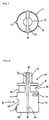
  • Fig.1 is a plan view of the buried type thermostat in accordance with a first embodiment of the present invention
  • Fig.2 is a front view of the buried type thermostat shown in Fig.1
  • Fig.3 is a side view of the buried type thermostat shown in Fig. 1
  • Fig.4 is a vertical cross-sectional view of the buried type thermostat shown in Fig.1.
  • Fig.5 and Fig.6 show the buried type thermostat being mounted inside the internal combustion engine and Fig.5 shows the thermostat closing the flow area and Fig.6 shows the thermostat opening the flow area.
  • Said buried type thermostat A comprises a case 1; a thermo valve 2 accommodated inside said case 1; a thermo electric element 10 which forcibly drives said thermo valve 2 by heating; a lid 3 screwed to an engine head B which is a mount member to block a bottom surface of the case 1; and a coil spring 4 loaded between the thermo valve 2 and the lid 3 to urge the thermo valve 2 upward.
  • Said case 1 is a hollow cylindrical shape and has an entrance opening 1a and an exit opening 1b formed therein in correspondence with a liquid coolant flow path 3 defined in the engine head B as shown in Fig. 5 and Fig. 6. Also, a bore 1d is formed beneath the entrance opening 1b in a peripheral surface (side wall) 1c of said case 1 such that a connection cord 10a connected to the thermo electric element 10 is introduced outside the peripheral surface 1c (side wall) of the case 1 therethrough.
  • an exit opening 1f for a bypass line is formed beneath the exit opening 1b in the peripheral surface (side wall) 1c of said case 1 and on the other hand, an entrance opening 1e for the bypass line is formed at the bottom of the case 1. Said entrance opening 1e and the exit opening if for the bypass line communicate with each other when an element (valve body) 2a to be described below closes the entrance opening 1a and the exit opening 1b. Also, a metallic ring 5 which supports a coil spring 4 is fitted into a recess 1g at the lower portion of the inner wall of the case 1.
  • a cap section 1i formed concentrically with the peripheral surface (side wall) 1c has a smaller diameter than the peripheral surface (side wall) 1c and is formed on the upper section 1h of said case 1 integrally with the case 1.
  • a connecting section 1j which connects the cap section 1i and the upper surface of the case 1 is formed on the upper section 1h of the case 1.
  • This connecting section 1j is formed intermediate between the entrance opening 1a and the exit opening 1b as shown in Fig.2. Thus, it is constructed to partition the entrance opening side 1a and the exit opening side 1b.
  • a continuous linear groove 1k is formed in the peripheral surface (side wall) 1c of said case 1, a ridgeline section 1j1 of the connecting section 1j and a top surface 1i1 of the cap section 1i such that a ring-shaped synthetic rubber member 6 is fitted into said groove 1k.
  • the groove 1k is also formed in the bottom periphery of the case 1 and the ring-shaped synthetic rubber member 6 is fitted thereinto but not projecting more than needed.
  • a positioning lug 11 is formed beneath the entrance opening 1a for the liquid coolant flow path 3 of said case 1. Also, a recess 7a is formed in the sidewall of an insertion hole 7 in correspondence with this positioning lug 11 such that said positioning lug 11 is secured in the recess 7a. Also,- a lid 3 in which a bypass line 3a is formed blocks the bottom surface of said case 1 by way of a sealing member 8.
  • thermo valve 2 is composed of a wax case 2c charged with an expansive wax 2b, a diaphragm 2e to transmit the expansion and the contraction of the wax 2b to a semi-fluid 2d on upper side, the semi-fluid 2d which transfers the reaction of the diaphragm 2e to a rubber piston 2f on the upper side, a back-up plate 2h which transmits the reaction of the semi-fluid 2d to a piston 2g on the upper side, and the piston 2g which pushes the cap section and an element (valve element) 2a, said component members being arranged in a laminated constitution.
  • said element (or valve element) 2a is adapted to slide along the inner wall surface 1m of the case 1 so as to open and close the entrance opening 1a and the exit opening 1b.
  • thermo electric element 10 which expands said wax 2b forcibly by heating wax case 2c is provided at the bottom surface of said thermo valve 2 (wax case 2c).
  • a connecting cord 10a to be connected with a power source is attached to the thermo electric element 10 and said connecting cord 10a is introduced outside the case 1 through the bore 1d as described above.
  • the thermo electric element described here includes a heating element such as PTC or dichromic heater.
  • the upper side opposing the bottom side of the wax case 2c is formed with a guide section 2c1 to guide the piston 2g.
  • the outer periphery of the guiding section 2c1 is formed in correspondence with the configuration of an inner wall In and formed to fit within said inner wall In to slide therealong.
  • the coil spring 4 is loaded in a space formed between the ring 5 and the thermo valve 2 and functions to always urge the thermo valve 2- upwardly-(refer to Fig.4 and Fig.5).
  • the coil spring 4 By the way, by changing the resiliency of the coil spring 4 or the overall height of the coil spring 4, it is able to adapt itself properly to changes in a set operation temperature, a set flow rate or the like of the buried type thermo element 1.
  • said lid 3 is formed with a thread, although not shown in the drawings, such that said lid 3 may be screwed onto the engine head B and secured thereon via a sealing member 8.
  • the thermostat A is assembled and the connecting cord 10a of the thermo electric element 10 is introduced outside through the bore 1a of the case 1. Also, an upper insertion hole 9 and the bottom insertion hole 7 are formed in the engine head B in advance.
  • the case 1 of the thermostat A is inserted into the upper insertion hole 9 and the lower insertion hole 7.
  • it is necessary to conduct positioning work such that entrance opening 1a and the exit opening 1b are in communication with the liquid coolant flow path 3 (refer to Fig.5 and Fig6).
  • the lid 3 is screwed onto the engine head B by way of a sealing member to close the bottom surface of the case 1.
  • connection cord 10a of said thermo electric element 10 is introduced outside the case 1 through the bore 1d of the case 1 and then introduced out from the insertion hole 7 through the space S formed between said insertion hole 7 and the case 1.
  • the connection cord 10a is then introduced out through the bore formed in the sealing member 8 and the bore of the lid 3 to be connected to the power source.
  • the thermo electric element 10 is also mounted at the time of -mounting of the thermostat. Also, there is no need to secure an extra space to mount the thermo electric element 10 thereto and able to avoid limitations arising due to the attachment of the thermo electric element 10.
  • said synthetic rubber member 6 closely fits in the upper insertion hole 9 and the insertion hole 7 so that the liquid coolant will not leak out through the space left between the peripheral surface4 1c of the case 1 and the upper insertion hole 9 or the lower insertion hole 7.
  • the liquid coolant inside the liquid coolant flow path 3 before the warming up is at a low temperature and this temperature is transmitted to the wax 2b inside the wax case 2c by way of the peripheral surface of the element (valve element) 2a and the wax case 2c (refer to Fig.5).
  • thermo valve 2 moves downward, the entrance opening 1a and the exit opening 1b of the case 1 closed by the outer peripheral surface of the element (valve element) 2a are opened to bring the flow path area FA into communication.
  • the liquid coolant flows from the radiator side to the engine side as shown in the bold arrows of Fig.6.
  • the power is supplied from the connecting cord 10a to heat the wax case 2c with the thermo electric element such that the wax 2b is expanded forcibly.
  • the entrance opening 1a and the exit opening 1b of the case 1 are opened to bring the flow path area FA into communication.
  • the outer peripheral surface of the element (valve element) 2a closes the entrance opening 1a and the exit opening 1b to finally block the flow path area FA (refer to Fig.5).
  • Fig.7 shows the buried type thermostat being located inside the internal combustion engine and also shows said thermostat closing the flow area.
  • This embodiment is structured by locating a liquid temperature sensor at the entrance opening 1a such that a connecting cord 11a of said liquid temperature sensor for the liquid temperature is introduced out through a bore 1p formed in the sidewall 1c of the case 1. Because other components are similar to those of the first embodiment, the description will be omitted.
  • Said bore 1p is formed to extend from the entrance opening 1a to the bottom surface of the case 1, and an opening of the bore 1p is formed in said bottom surface. Therefore, although not shown in the drawings, the connecting cord 10a is introduced out through the bore 1p by way of the sealing member 8 and the lid 3.
  • the liquid temperature sensor 11 and the thermostat A are able to be bodily mounted at the same time by way of mounting the thermostat A provided with the liquid temperature sensor 11 to the internal combustion engine. Also, there is no need to secure an extra space to locate the liquid temperature sensor 11 therein and is free from limitations arising from the attachment of the liquid temperature sensor 11.
  • Fig.8(a) is a side view of the thermostat in accordance with the third embodiment of the present invention and Fig.8(b) is a front view of the thermostat in accordance with the third embodiment of the present invention;
  • This embodiment is structured by forming a bore 1q in the connecting section 1j of the case 1 and said bore 1q is provided with a jiggle valve 12.
  • Said jiggle valve 12 is composed of valve bodies 12a and 12b, a jiggle pin 12c having said valve body 12a and 12b formed on the opposite ends thereof. And the jiggle valve 12 is mounted to the case 1 by inserting said jiggle pin 12c into said bore 1q.
  • the entrance opening 1a side and the exit opening 1b side of the liquid coolant are partitioned by the peripheral surface of the case 1c, the connecting section 1j and the upper surface of the cap section 1i (the synthetic rubber member 6 covering the peripheral surface of the case, the connecting section and the upper surface of the cap section), said entrance opening 1a side and said exit opening 1b side are brought into communication by said bore 1q such that the opening and the closing is performed with said valve body 12a and 12b (jiggle valve 12).
  • This valve bodies 12a and 12b (jiggle valve 12) defines a path to let the air out when supplying the liquid coolant and perform similar action as the conventional jiggle valve. Therefore, a detailed description thereof will be omitted here.
  • the jiggle valve 12 and the thermostat A are able to be bodily mounted by mounting the thermostat A composed of a jiggle valve 12 to the internal combustion engine. Also, there is no need to secure an extra space to attach jiggle valve 12 thereto and able to avoid limitations arising from the location of the jiggle valve 12.
  • Fig.9 is a vertical cross-sectional view showing the buried type thermostat being located inside the internal combustion engine and also shows the thermostat closing the flow area.
  • This embodiment is structured by forming a bore 1r in the sidewall (peripheral surface) 1c of the case and said bore 1r is provided with a jiggle valve 13. Because other components are similar to those of the first embodiment, the description will be omitted.
  • Said jiggle valve 13 composed of a jiggle ball 13a and a jiggle valve body 13b.
  • Said jiggle valve body 13b accommodates said jiggle ball 13a in an accommodating section 13e formed therein and provided with an outer opening 13c and an inner opening 13d to be blocked by said jiggle ball 13a.
  • said jiggle valve body is inserted into the bore 1r in the sidewall (peripheral surface) 1c of the case 1 to be secured to the case 1.
  • This jiggle ball 13a has a similar function as a valve bodies 12a and 12b (jiggle valve 12) of the third embodiment such that a path to let the air out when supplying the liquid coolant is defined. A detailed description will be omitted here.
  • the jiggle valve 13 and the thermostat A are able to be bodily mounted in a body by mounting the thermostat A principally composed of a jiggle valve 13 to the internal combustion engine. Also, there is no need to secure an extra space to fit jiggle valve 13 and is free from limitations arising from the attachment of the jiggle valve 13.
  • thermostat in the embodiments described above is a buried type thermostat applied to a liquid coolant flow path formed in an engine head
  • its layout position is not limited to the engine head but said thermostat may be mounted also to an engine block, in side a radiator, at a branch point of a bypass line or the like as long as it is within the liquid coolant flow path.
  • the thermostat in accordance with the present invention is able to layout the liquid flow path efficiently by burying the thermostat to a member into which the same is to be buried and also mount the thermostat easily.

Landscapes

  • Engineering & Computer Science (AREA)
  • Chemical & Material Sciences (AREA)
  • Combustion & Propulsion (AREA)
  • Mechanical Engineering (AREA)
  • General Engineering & Computer Science (AREA)
  • Temperature-Responsive Valves (AREA)

Abstract

The present invention provides a structure of a thermostat case which enables an efficient layout of a liquid flow path by burying the thermostat to a mount member such as an engine head or the like, and also enables to mount the thermostat easily and furthermore enables to place a liquid temperature sensor and a jiggle valve or the like by making the best use of the thermostat case. This structure of the thermostat case is composed of a cylindrical case formed with an entrance opening and an exit opening in a peripheral surface thereof, a flow path area defined within said cylindrical case (1) to bring said entrance opening (1a) and said exit opening (1b) into communication with each other, a valve element (2) moving back and forth across said flow path area in response to a temperature change of a liquid coolant which flows in said flow path area to provide blockage and communication thereof by opening and closing said entrance opening and said exit opening with its movement and a thermostat which is buried into the insertion hole of the member provided with a liquid coolant flow path, wherein a bore (1d) is formed in said case (1).

Description

Field of Art
The present invention relates to a thermostat case structure in which said thermostat case is mounted to an internal combustion engine for controlling the flow of a liquid coolant by blockage and communication of a liquid flow path, and particularly to a thermostat case structure for effective uses of a case which constitutes a thermostat.
Background of Art
The majority of the cooling system for an automotive internal combustion engine presently available on the market is designed to cool the engine by water used as a liquid coolant or a liquid cooling medium. This type of cooling system is known as the water cooled type cooling system which is employed for engines of four-wheeled vehicles as well as engines of two-wheeled vehicles.
Said water cooled type cooling system for an automotive internal combustion engine mentioned above is provided with a radiator outside the engine body, making it necessary to circulate the liquid coolant by connecting the radiator and the engine body with a rubber hose or the like. Thus, the system is comprised of a radiator acting as a heat exchanger, a water pump which sends the liquid coolant from the engine to the radiator forcibly under pressure, a thermostat which controls a flow of the liquid coolant on the basis of the temperature of the liquid coolant flowing out of or into the radiator to maintain a suitable temperature,-and a rubber hose or the like which defines a circular flow path of the liquid coolant.
Thus, such structure prevents an overheating caused by the heat from the engine and on the other hand it prevents an over cooling in a cold season, thus always maintaining the engine temperature at an optimum level.
A thermostat in general and a structure for mounting such thermostat to be employed for aforementioned water cooled type system will be described with reference to Fig. 10 (a), Fig. 10 (b) and Fig. 11. Fig. 10 (a) and Fig. 10 (b) are explanatory views in which the conventional thermostat is mounted to the liquid coolant flow path of an internal combustion engine and Fig. 11 is an enlarged view of the thermostat being mounted as shown in Figs. 10(a) and 10(b).
As shown in said figures, a thermostat 100 is arranged to be mounted at a predetermined position in a liquid coolant flow path 110 defined between a body of an engine E and a radiator R. Also, as shown in Fig. 11, said thermostat 100 is provided with a piston 102 which moves back and forth as a result of the action of an element 101. Said thermostat 100 is arranged in the liquid coolant flow path 110 such that the moving direction of the piston 102 is set parallel to a flow direction of the liquid coolant.
Further, in said thermostat 100, a valve element 103 and a valve seat 104 come into and out of contact with each other by the reciprocal action of the piston 102 to assure blockage and communication of the liquid coolant flow path.
Still, in Fig. 11, the numeral 105 denotes a guide section to guide the piston 102 for reciprocal action thereof, the numeral 106 denotes a wax case charged with wax, the numeral 107 denotes a second valve element to close or to open a bypass line 110A. Moreover, in Figs. 10, the letter P denotes a water pump and the letter R denotes a radiator.
Hereinafter, an operation of said thermostat 100 will be described hereinafter with reference to Fig. 10 (a). As shown in Fig. 10 (a), the thermostat 100 causes the liquid coolant flow path 110 to be closed from the time when the engine is started until the time when the engine has been warmed up to an optimum temperature.
Thus, the water coolant from the engine E will not flow into the radiator R but circulate back to the engine E by way of the bypass line 110A (see the arrow marks in Fig.10 (a)) such that the engine is warmed up to the optimum temperature quickly.
On the other hand, after the engine E has been warmed up to said optimum temperature, the valve element 103 of the thermostat 100 opens as shown in Fig. 10 (b), such that the liquid coolant flow path 110 of the radiator side is brought into communication. As a result, the liquid coolant circulates to the engine E by way of the radiator R (see the arrow marks in Fig.10 (b)) and therefore the inside of the engine E is cooled to maintain the temperature at an optimum level.
However, since said conventional thermostat is located inside the liquid coolant flow path, a pipe diameter of the liquid coolant flow path 110 where the thermostat 100 is located is required to be large enough to maintain the flow of the liquid coolant in a predetermined quantity within the liquid flow path. Such large diameter of the liquid flow path is found detrimental to effective layout designing. In addition, there are many limitations to the place where the thermostat can be located and further, it is difficult to conduct a mounting operation of the thermostat.
To solve the problems as described above, a buried type thermostat which is designed to be buried in an insertion hole 120c formed across the liquid coolant flow path 121 in an engine head 120 has already been proposed as shown in Fig. 12 (Japanese Patent Application No. 11-17923).
By the way, there is a conventional cooling system for the automotive internal combustion engine provided with a liquid temperature sensor to drive an electric cooling fan on the radiator move when the temperature of the liquid coolant exceeds the predetermined temperature. Said liquid temperature sensor is provided separately from the thermostat.
Therefore, a place wherein said liquid temperature sensor is located and also a process for locating said sensor is necessary.
Further, when the liquid coolant is to be supplied into the radiator or the water jacket, the air needs to be let out. In the automotive internal combustion engine, a so-called jiggle valve is comprised to let out air. However, this jiggle valve also needs a place where the same is to be located and an operation for mounting the jiggle valve like said liquid temperature sensor.
Summary of the Invention
The present invention is made to solve the above mentioned subject and it is an object of the present invention to provide a structure of a thermostat case which enables an efficient layout of a liquid flow path by burying the thermostat to a mount member such as an engine head or the like, and also enables to mount the thermostat easily and furthermore enables to mount a liquid temperature sensor and a jiggle valve or the like by effective uses of the case of the thermostat.
A structure of a thermostat case in accordance with the present invention to solve the above mentioned problem is composed of a cylindrical case formed with an entrance opening and an exit opening in a peripheral surface thereof, a flow path area defined within said cylindrical case to bring said entrance opening and said exit opening into communication with each other, a valve element moving back and forth to move across said flow path area in response to a temperature change of a liquid coolant which flows through said flow path area to provide blockage and communication thereof and a thermostat which is buried in the insertion hole of a mount member provided with a liquid coolant flow path, and a bore formed in said case.
Because the bore is formed in the thermostat case, a liquid temperature sensor and a jiggle valve are able to be fitted to the thermostat such that the liquid temperature sensor and the jiggle valve are able to be bodily mounted to a cooling system. Because the thermostat is buried into the insertion hole of the mount member provided with the liquid coolant flow path, the thermostat can be mounted easily and efficient layout designing is possible.
Here, said case may be provided with a cylindrical cap section projecting from the upper-end surface of the case and a connecting section connecting the upper-end surface of said case and the cap section and a bore may be formed in either one of a side wall of said cylindrical case, a cap section an a connecting section.
Further, it is desirable that a connecting cord of an electric device to be fitted to the thermostat is inserted through the bore formed in said case.
Because a connecting cord of the electric device fitted to the thermostat, for example, the temperature sensor for the liquid coolant, a PTC which heats up a wax case forcibly, a thermo electric element such as dichromic heater or the like, is inserted through the bore, mounting of the electric devices and wiring therefore can be done while the thermostat is bodily mounted to the mount member into which the thermostat is buried.
Moreover, it is desirable that a jiggle ball and the jiggle valve having a jiggle ball accommodation section to accommodate said jiggle ball therein are provided within the bore of said case and it is also desirable that the jiggle valve having the valve body and a jiggle pin formed on opposite ends thereof is fitted to the case by inserting said jiggle pin through the bore of said case.
Because the so-called jiggle valve is fitted in the insertion hole of the case, the jiggle valve can be fitted at the time of the mounting of the thermostat.
Brief description of Drawings
  • Fig.1 is a plan view of the buried type thermostat in accordance with a first embodiment of the present invention;
  • Fig.2 is a front view of the buried type thermostat shown in Fig.1;
  • Fig.3 is a side view of the buried type thermostat shown in Fig.1;
  • Fig.4 is a vertical cross-sectional view of the buried type thermostat shown in Fig.1;
  • Fig.5 shows the buried type thermostat being mounted inside the internal combustion engine and also shows the thermostat closing the flow area;
  • Fig.6 shows the buried type thermostat being mounted inside the internal combustion engine and also shows the thermostat opening the flow area;
  • Fig.7 is a vertical cross-sectional view of the thermostat in accordance with a second embodiment of the present invention;
  • Fig.8(a) and Fig.8(b) show the thermostat in accordance with the third embodiment of the present invention;
  • Fig.9 shows the thermostat in accordance with the fourth embodiment of the present invention;
  • Fig.10(a) and Fig.10(b) are explanatory views showing the conventional thermostat being mounted to the liquid coolant flow line of the general internal combustion engine in general; and
  • Fig.11 is an enlarged view of the mounting section of the thermostat shown in Figs.10.
  • Preferred Embodiments of the Present Invention
    The first embodiment of the present invention is described concretely with reference to Fig.1 through Fig.6.
    Here, Fig.1 is a plan view of the buried type thermostat in accordance with a first embodiment of the present invention, Fig.2 is a front view of the buried type thermostat shown in Fig.1, Fig.3 is a side view of the buried type thermostat shown in Fig. 1 and Fig.4 is a vertical cross-sectional view of the buried type thermostat shown in Fig.1. Also, Fig.5 and Fig.6 show the buried type thermostat being mounted inside the internal combustion engine and Fig.5 shows the thermostat closing the flow area and Fig.6 shows the thermostat opening the flow area.
    Said buried type thermostat A comprises a case 1; a thermo valve 2 accommodated inside said case 1; a thermo electric element 10 which forcibly drives said thermo valve 2 by heating; a lid 3 screwed to an engine head B which is a mount member to block a bottom surface of the case 1; and a coil spring 4 loaded between the thermo valve 2 and the lid 3 to urge the thermo valve 2 upward.
    Said case 1 is a hollow cylindrical shape and has an entrance opening 1a and an exit opening 1b formed therein in correspondence with a liquid coolant flow path 3 defined in the engine head B as shown in Fig. 5 and Fig. 6. Also, a bore 1d is formed beneath the entrance opening 1b in a peripheral surface (side wall) 1c of said case 1 such that a connection cord 10a connected to the thermo electric element 10 is introduced outside the peripheral surface 1c (side wall) of the case 1 therethrough.
    Moreover, an exit opening 1f for a bypass line is formed beneath the exit opening 1b in the peripheral surface (side wall) 1c of said case 1 and on the other hand, an entrance opening 1e for the bypass line is formed at the bottom of the case 1. Said entrance opening 1e and the exit opening if for the bypass line communicate with each other when an element (valve body) 2a to be described below closes the entrance opening 1a and the exit opening 1b. Also, a metallic ring 5 which supports a coil spring 4 is fitted into a recess 1g at the lower portion of the inner wall of the case 1.
    A cap section 1i formed concentrically with the peripheral surface (side wall) 1c has a smaller diameter than the peripheral surface (side wall) 1c and is formed on the upper section 1h of said case 1 integrally with the case 1. Also a connecting section 1j which connects the cap section 1i and the upper surface of the case 1 is formed on the upper section 1h of the case 1. This connecting section 1j is formed intermediate between the entrance opening 1a and the exit opening 1b as shown in Fig.2. Thus, it is constructed to partition the entrance opening side 1a and the exit opening side 1b.
    Moreover, a continuous linear groove 1k is formed in the peripheral surface (side wall) 1c of said case 1, a ridgeline section 1j1 of the connecting section 1j and a top surface 1i1 of the cap section 1i such that a ring-shaped synthetic rubber member 6 is fitted into said groove 1k. Here, the groove 1k is also formed in the bottom periphery of the case 1 and the ring-shaped synthetic rubber member 6 is fitted thereinto but not projecting more than needed.
    Furthermore, a positioning lug 11 is formed beneath the entrance opening 1a for the liquid coolant flow path 3 of said case 1. Also, a recess 7a is formed in the sidewall of an insertion hole 7 in correspondence with this positioning lug 11 such that said positioning lug 11 is secured in the recess 7a. Also,- a lid 3 in which a bypass line 3a is formed blocks the bottom surface of said case 1 by way of a sealing member 8.
    Hereinafter, said thermo valve 2 will be described in detail. The thermo valve 2 is composed of a wax case 2c charged with an expansive wax 2b, a diaphragm 2e to transmit the expansion and the contraction of the wax 2b to a semi-fluid 2d on upper side, the semi-fluid 2d which transfers the reaction of the diaphragm 2e to a rubber piston 2f on the upper side, a back-up plate 2h which transmits the reaction of the semi-fluid 2d to a piston 2g on the upper side, and the piston 2g which pushes the cap section and an element (valve element) 2a, said component members being arranged in a laminated constitution. Also, said element (or valve element) 2a is adapted to slide along the inner wall surface 1m of the case 1 so as to open and close the entrance opening 1a and the exit opening 1b.
    A thermo electric element 10 which expands said wax 2b forcibly by heating wax case 2c is provided at the bottom surface of said thermo valve 2 (wax case 2c). A connecting cord 10a to be connected with a power source is attached to the thermo electric element 10 and said connecting cord 10a is introduced outside the case 1 through the bore 1d as described above. The thermo electric element described here includes a heating element such as PTC or dichromic heater.
    By the way, the upper side opposing the bottom side of the wax case 2c is formed with a guide section 2c1 to guide the piston 2g. The outer periphery of the guiding section 2c1 is formed in correspondence with the configuration of an inner wall In and formed to fit within said inner wall In to slide therealong.
    Also, the coil spring 4 is loaded in a space formed between the ring 5 and the thermo valve 2 and functions to always urge the thermo valve 2- upwardly-(refer to Fig.4 and Fig.5). By the way, by changing the resiliency of the coil spring 4 or the overall height of the coil spring 4, it is able to adapt itself properly to changes in a set operation temperature, a set flow rate or the like of the buried type thermo element 1.
    Furthermore, said lid 3 is formed with a thread, although not shown in the drawings, such that said lid 3 may be screwed onto the engine head B and secured thereon via a sealing member 8.
    Next, a method of mounting the buried type thermostat A will be described hereinafter.
    At first, the thermostat A is assembled and the connecting cord 10a of the thermo electric element 10 is introduced outside through the bore 1a of the case 1. Also, an upper insertion hole 9 and the bottom insertion hole 7 are formed in the engine head B in advance.
    Then, the case 1 of the thermostat A is inserted into the upper insertion hole 9 and the lower insertion hole 7. For this insertion, it is necessary to conduct positioning work such that entrance opening 1a and the exit opening 1b are in communication with the liquid coolant flow path 3 (refer to Fig.5 and Fig6). Then, with the case 1 being inserted into the insertion hole 7 and 9, the lid 3 is screwed onto the engine head B by way of a sealing member to close the bottom surface of the case 1.
    At this time, the connection cord 10a of said thermo electric element 10 is introduced outside the case 1 through the bore 1d of the case 1 and then introduced out from the insertion hole 7 through the space S formed between said insertion hole 7 and the case 1. The connection cord 10a is then introduced out through the bore formed in the sealing member 8 and the bore of the lid 3 to be connected to the power source. Thus, the thermo electric element 10 is also mounted at the time of -mounting of the thermostat. Also, there is no need to secure an extra space to mount the thermo electric element 10 thereto and able to avoid limitations arising due to the attachment of the thermo electric element 10.
    By the way, when said case 1 is assembled onto the engine head B, said synthetic rubber member 6 closely fits in the upper insertion hole 9 and the insertion hole 7 so that the liquid coolant will not leak out through the space left between the peripheral surface4 1c of the case 1 and the upper insertion hole 9 or the lower insertion hole 7.
    Next, a function of the buried type thermostat A in accordance with the instant embodiment will be described hereinafter (refer to Fig.2 and Fig.3).
    At first, the transfer of the buried type thermostat A from the closed status to the opened status will be described. The liquid coolant inside the liquid coolant flow path 3 before the warming up is at a low temperature and this temperature is transmitted to the wax 2b inside the wax case 2c by way of the peripheral surface of the element (valve element) 2a and the wax case 2c (refer to Fig.5).
    Then, as the temperature of the liquid coolant inside the liquid coolant flow path 3 rises with the lapse of time, the wax 2b inside the wax case 2c expands to increase its volume. And in response to this volume increase, the diaphragm 2e bulges to the upper side, giving rise to a force to push the rubber piston 2g upward via semi-fluid 2d on the upper side. This force is transmitted to the piston 2g via backup plate 2h such that the piston 2g acts to project out from the guide section 2c1. However, because a tip of the piston 2g is always in contact with the rigidly secured cap section, the element (valve element) 2a itself is pushed down by a relative movement against the piston 15f by overcoming the urge of the coil spring 4.
    Then, as the thermo valve 2 moves downward, the entrance opening 1a and the exit opening 1b of the case 1 closed by the outer peripheral surface of the element (valve element) 2a are opened to bring the flow path area FA into communication. As a result, the liquid coolant flows from the radiator side to the engine side as shown in the bold arrows of Fig.6.
    Also, to transfer the thermostat forcibly from the closed status to the opened status without any effects from the temperature of the liquid coolant, the power is supplied from the connecting cord 10a to heat the wax case 2c with the thermo electric element such that the wax 2b is expanded forcibly. As a result, the entrance opening 1a and the exit opening 1b of the case 1 are opened to bring the flow path area FA into communication.
    Next, the transfer of the buried type thermostat A from the opened status to the closed status will be described. When the operation of the engine is stopped, the action of the water pump causes to stop the circulation of the liquid coolant inside the liquid coolant flow path 3. Then, as the temperature of the liquid coolant inside the liquid coolant flow path 3 decreases with the lapse of time, this change in the temperature is transmitted to the wax 2b inside the wax case 2c by way of the element (or valve element) 2a and the wax case 2c. And as the temperature decreases, the expanded wax 2b inside the wax case 2c contracts such that the thermo valve moves upward with the urge of the coil spring 4 which always gives a force to push the thermo valve 2 upward.
    As a result, the outer peripheral surface of the element (valve element) 2a closes the entrance opening 1a and the exit opening 1b to finally block the flow path area FA (refer to Fig.5).
    Next, the second embodiment of the present invention will be described concretely with reference to Fig.7.
    Here, Fig.7 shows the buried type thermostat being located inside the internal combustion engine and also shows said thermostat closing the flow area.
    This embodiment is structured by locating a liquid temperature sensor at the entrance opening 1a such that a connecting cord 11a of said liquid temperature sensor for the liquid temperature is introduced out through a bore 1p formed in the sidewall 1c of the case 1. Because other components are similar to those of the first embodiment, the description will be omitted.
    Said bore 1p is formed to extend from the entrance opening 1a to the bottom surface of the case 1, and an opening of the bore 1p is formed in said bottom surface. Therefore, although not shown in the drawings, the connecting cord 10a is introduced out through the bore 1p by way of the sealing member 8 and the lid 3.
    As described above, the liquid temperature sensor 11 and the thermostat A are able to be bodily mounted at the same time by way of mounting the thermostat A provided with the liquid temperature sensor 11 to the internal combustion engine. Also, there is no need to secure an extra space to locate the liquid temperature sensor 11 therein and is free from limitations arising from the attachment of the liquid temperature sensor 11.
    Next, the third embodiment of the present invention will be described concretely with reference to Figs.8(a) and 8(b).
    Fig.8(a) is a side view of the thermostat in accordance with the third embodiment of the present invention and Fig.8(b) is a front view of the thermostat in accordance with the third embodiment of the present invention;
    This embodiment is structured by forming a bore 1q in the connecting section 1j of the case 1 and said bore 1q is provided with a jiggle valve 12. Said jiggle valve 12 is composed of valve bodies 12a and 12b, a jiggle pin 12c having said valve body 12a and 12b formed on the opposite ends thereof. And the jiggle valve 12 is mounted to the case 1 by inserting said jiggle pin 12c into said bore 1q.
    By the way, because other components are similar to those of the first embodiment, the description thereof will be omitted.
    Therefore, while the case 1 is inserted onto the engine head B, the entrance opening 1a side and the exit opening 1b side of the liquid coolant are partitioned by the peripheral surface of the case 1c, the connecting section 1j and the upper surface of the cap section 1i (the synthetic rubber member 6 covering the peripheral surface of the case, the connecting section and the upper surface of the cap section), said entrance opening 1a side and said exit opening 1b side are brought into communication by said bore 1q such that the opening and the closing is performed with said valve body 12a and 12b (jiggle valve 12).
    This valve bodies 12a and 12b (jiggle valve 12) defines a path to let the air out when supplying the liquid coolant and perform similar action as the conventional jiggle valve. Therefore, a detailed description thereof will be omitted here.
    As described above, the jiggle valve 12 and the thermostat A are able to be bodily mounted by mounting the thermostat A composed of a jiggle valve 12 to the internal combustion engine. Also, there is no need to secure an extra space to attach jiggle valve 12 thereto and able to avoid limitations arising from the location of the jiggle valve 12.
    Next, the fourth embodiment of the present invention is described concretely with reference to Fig.9.
    Here, Fig.9 is a vertical cross-sectional view showing the buried type thermostat being located inside the internal combustion engine and also shows the thermostat closing the flow area.
    This embodiment is structured by forming a bore 1r in the sidewall (peripheral surface) 1c of the case and said bore 1r is provided with a jiggle valve 13. Because other components are similar to those of the first embodiment, the description will be omitted.
    Said jiggle valve 13 composed of a jiggle ball 13a and a jiggle valve body 13b. Said jiggle valve body 13b accommodates said jiggle ball 13a in an accommodating section 13e formed therein and provided with an outer opening 13c and an inner opening 13d to be blocked by said jiggle ball 13a. And, said jiggle valve body is inserted into the bore 1r in the sidewall (peripheral surface) 1c of the case 1 to be secured to the case 1.
    Therefore, when said jiggle ball 13a is not blocking the outer opening 13c and the inner opening 13d, said accommodating section 13e and the inside of the case 1 are brought into communication with each other. This jiggle ball 13a has a similar function as a valve bodies 12a and 12b (jiggle valve 12) of the third embodiment such that a path to let the air out when supplying the liquid coolant is defined. A detailed description will be omitted here.
    As described above, the jiggle valve 13 and the thermostat A are able to be bodily mounted in a body by mounting the thermostat A principally composed of a jiggle valve 13 to the internal combustion engine. Also, there is no need to secure an extra space to fit jiggle valve 13 and is free from limitations arising from the attachment of the jiggle valve 13.
    By the way, although the thermostat in the embodiments described above is a buried type thermostat applied to a liquid coolant flow path formed in an engine head, its layout position is not limited to the engine head but said thermostat may be mounted also to an engine block, in side a radiator, at a branch point of a bypass line or the like as long as it is within the liquid coolant flow path.
    As described above, with the structure of the case of the thermostat in accordance with the present invention, it is able to layout the liquid flow path efficiently by burying the thermostat to a member into which the same is to be buried and also mount the thermostat easily.
    Further, it is able to mount a liquid temperature sensor and a jiggle valve or the like easily and bodily together with thermostat by making the best use of the thermostat case.

    Claims (5)

    1. A structure of a thermostat case comprising a cylindrical case formed with an entrance opening and an exit opening in a peripheral surface thereof; a flow path area defined within said cylindrical case to bring said entrance opening and said exit opening into communication with each other; a valve element moving back and forth across said flow path area in response to a temperature change of a liquid coolant flowing in said flow path area to provide blockage and communication to said flow path area by opening and closing said entrance opening and said exit opening with its movement; and a thermostat buried into an insertion hole of a mount member provided with a liquid coolant flow path, said case being formed with a bore.
    2. A structure of a thermostat case as set forth in claim 1, wherein said case is provided with a cylindrical cap section projecting from the upper-end surface of the case and a connecting section connecting the upper-end surface of said case and the cap section, said bore being formed in either one of a side wall of the cylindrical case, a cap section and a connecting section.
    3. A structure of a thermostat case as set forth in claim 1 or claim 2, wherein a connecting cord of electric devices connected to the thermostat is inserted into the bore of said case.
    4. A structure of a thermostat case as set forth in claim 1, claim 2 or claim3, wherein a jiggle valve provided with a jiggle ball and a jiggle ball accommodation section accommodating said jiggle ball therein are formed in the bore of said case.
    5. A structure of a thermostat case as set forth in claim 1, claim 2 or claim3, wherein a jiggle valve provided with valve bodies and a jiggle pin, said valve bodies being formed on the opposite ends of said jiggle pin, said jiggle pin being inserted through the bore of said case to be fitted therein.
    EP01947925A 2000-07-25 2001-07-09 Case structure of thermostat Expired - Lifetime EP1219879B1 (en)

    Applications Claiming Priority (3)

    Application Number Priority Date Filing Date Title
    JP2000022331 2000-07-25
    JP2000223311A JP4408539B2 (en) 2000-07-25 2000-07-25 Thermostat case structure
    PCT/JP2001/005938 WO2002008648A1 (en) 2000-07-25 2001-07-09 Case structure of thermostat

    Publications (3)

    Publication Number Publication Date
    EP1219879A1 true EP1219879A1 (en) 2002-07-03
    EP1219879A4 EP1219879A4 (en) 2009-12-23
    EP1219879B1 EP1219879B1 (en) 2011-06-01

    Family

    ID=29217454

    Family Applications (1)

    Application Number Title Priority Date Filing Date
    EP01947925A Expired - Lifetime EP1219879B1 (en) 2000-07-25 2001-07-09 Case structure of thermostat

    Country Status (2)

    Country Link
    EP (1) EP1219879B1 (en)
    WO (1) WO2002008648A1 (en)

    Cited By (2)

    * Cited by examiner, † Cited by third party
    Publication number Priority date Publication date Assignee Title
    EP1602809A4 (en) * 2003-03-11 2008-07-16 Honda Motor Co Ltd THERMOSTAT FIXING STRUCTURE
    US9285049B2 (en) * 2010-02-18 2016-03-15 Nippon Thermostat Co., Ltd. Thermostat device

    Families Citing this family (1)

    * Cited by examiner, † Cited by third party
    Publication number Priority date Publication date Assignee Title
    TR2022013824A2 (en) * 2022-09-05 2023-11-21 Kirpart Otomotiv Parcalari Sanayi Ve Ticaret Anonim Sirketi A THERMOELEMENT THAT RESPONSES FASTER TO REFRIGERANT TEMPERATURE

    Family Cites Families (9)

    * Cited by examiner, † Cited by third party
    Publication number Priority date Publication date Assignee Title
    DE2657512C2 (en) * 1976-12-18 1986-02-27 Gustav Wahler Gmbh U. Co, 7300 Esslingen Thermostatic valve
    JPS5932767Y2 (en) * 1979-08-11 1984-09-13 株式会社デンソー Engine cooling water thermostat
    JPS5725114U (en) * 1980-07-18 1982-02-09
    JPS5727571U (en) * 1980-07-22 1982-02-13
    JPS6021593Y2 (en) * 1981-06-30 1985-06-27 トヨタ自動車株式会社 temperature sensitive control valve
    JP2932348B2 (en) * 1994-03-14 1999-08-09 日本サーモスタット株式会社 thermostat
    JPH08121134A (en) * 1994-10-26 1996-05-14 Nippon Thermostat Kk Oil valve
    JPH1117923A (en) 1997-06-27 1999-01-22 Sanyo Electric Co Ltd Facsimile equipment
    JP4262346B2 (en) * 1999-01-27 2009-05-13 本田技研工業株式会社 thermostat

    Cited By (2)

    * Cited by examiner, † Cited by third party
    Publication number Priority date Publication date Assignee Title
    EP1602809A4 (en) * 2003-03-11 2008-07-16 Honda Motor Co Ltd THERMOSTAT FIXING STRUCTURE
    US9285049B2 (en) * 2010-02-18 2016-03-15 Nippon Thermostat Co., Ltd. Thermostat device

    Also Published As

    Publication number Publication date
    WO2002008648A1 (en) 2002-01-31
    EP1219879A4 (en) 2009-12-23
    WO2002008648A8 (en) 2002-07-11
    EP1219879B1 (en) 2011-06-01

    Similar Documents

    Publication Publication Date Title
    JP4262346B2 (en) thermostat
    TW397896B (en) The flowing control method of cooling media and its device
    KR101519961B1 (en) Transmission oil bypass assembly
    US7370612B2 (en) Internal combustion engine cooling system
    CN105019996B (en) Engine-cooling system expands liquid storage device
    US6742716B1 (en) Thermostat
    CN102207023B (en) thermostat device
    JP2001317355A (en) Thermostat device
    CN110630729B (en) Temperature regulating valve
    JP4498636B2 (en) Thermostat device
    JP6257037B2 (en) Thermostat device
    CN101133235B (en) thermostat unit
    EP1304459A1 (en) Seal member, and construction for attaching thermostats using this seal member
    EP1219879B1 (en) Case structure of thermostat
    JP3582055B2 (en) Mounting structure of thermostat
    JP4408539B2 (en) Thermostat case structure
    EP1304517B1 (en) Thermostat and mounting structure of the thermostat
    JP2786172B2 (en) Thermal response valve for controlling the refrigerant circuit of an automobile engine
    JPS5939452Y2 (en) Oil filter with thermo valve
    JPH08210553A (en) Thermostat

    Legal Events

    Date Code Title Description
    PUAI Public reference made under article 153(3) epc to a published international application that has entered the european phase

    Free format text: ORIGINAL CODE: 0009012

    AK Designated contracting states

    Kind code of ref document: A1

    Designated state(s): AT BE CH CY DE DK ES FI FR GB GR IE IT LI LU MC NL PT SE TR

    AX Request for extension of the european patent

    Free format text: AL;LT;LV;MK;RO;SI

    17P Request for examination filed

    Effective date: 20020528

    RBV Designated contracting states (corrected)

    Designated state(s): AT IT

    REG Reference to a national code

    Ref country code: DE

    Ref legal event code: 8566

    A4 Supplementary search report drawn up and despatched

    Effective date: 20091123

    17Q First examination report despatched

    Effective date: 20100611

    RIC1 Information provided on ipc code assigned before grant

    Ipc: F16K 31/68 20060101AFI20101130BHEP

    GRAP Despatch of communication of intention to grant a patent

    Free format text: ORIGINAL CODE: EPIDOSNIGR1

    GRAS Grant fee paid

    Free format text: ORIGINAL CODE: EPIDOSNIGR3

    GRAA (expected) grant

    Free format text: ORIGINAL CODE: 0009210

    AK Designated contracting states

    Kind code of ref document: B1

    Designated state(s): IT

    PLBE No opposition filed within time limit

    Free format text: ORIGINAL CODE: 0009261

    STAA Information on the status of an ep patent application or granted ep patent

    Free format text: STATUS: NO OPPOSITION FILED WITHIN TIME LIMIT

    26N No opposition filed

    Effective date: 20120302

    PG25 Lapsed in a contracting state [announced via postgrant information from national office to epo]

    Ref country code: IT

    Free format text: LAPSE BECAUSE OF NON-PAYMENT OF DUE FEES

    Effective date: 20120709