EP1219801A2 - Gasturbine - Google Patents
Gasturbine Download PDFInfo
- Publication number
- EP1219801A2 EP1219801A2 EP01128786A EP01128786A EP1219801A2 EP 1219801 A2 EP1219801 A2 EP 1219801A2 EP 01128786 A EP01128786 A EP 01128786A EP 01128786 A EP01128786 A EP 01128786A EP 1219801 A2 EP1219801 A2 EP 1219801A2
- Authority
- EP
- European Patent Office
- Prior art keywords
- booster
- booster stage
- turbomachine
- duct
- stage
- Prior art date
- Legal status (The legal status is an assumption and is not a legal conclusion. Google has not performed a legal analysis and makes no representation as to the accuracy of the status listed.)
- Granted
Links
- 239000007789 gas Substances 0.000 claims description 90
- 238000000034 method Methods 0.000 claims description 16
- 239000012530 fluid Substances 0.000 claims description 13
- 239000002918 waste heat Substances 0.000 claims description 12
- 238000001816 cooling Methods 0.000 claims description 7
- 238000005516 engineering process Methods 0.000 claims description 4
- 238000010304 firing Methods 0.000 claims description 4
- 238000011010 flushing procedure Methods 0.000 claims description 3
- 230000009467 reduction Effects 0.000 claims description 3
- 238000011084 recovery Methods 0.000 claims description 2
- 230000006698 induction Effects 0.000 abstract 1
- 239000003570 air Substances 0.000 description 29
- 238000002485 combustion reaction Methods 0.000 description 7
- 239000000446 fuel Substances 0.000 description 7
- 230000005611 electricity Effects 0.000 description 5
- 230000008569 process Effects 0.000 description 5
- 239000012080 ambient air Substances 0.000 description 3
- 230000008859 change Effects 0.000 description 3
- 238000005457 optimization Methods 0.000 description 3
- 230000003247 decreasing effect Effects 0.000 description 2
- 230000000694 effects Effects 0.000 description 2
- 230000007613 environmental effect Effects 0.000 description 2
- 238000009434 installation Methods 0.000 description 2
- 238000010926 purge Methods 0.000 description 2
- 230000001932 seasonal effect Effects 0.000 description 2
- 239000000126 substance Substances 0.000 description 2
- 230000001133 acceleration Effects 0.000 description 1
- 230000033228 biological regulation Effects 0.000 description 1
- 230000008878 coupling Effects 0.000 description 1
- 238000010168 coupling process Methods 0.000 description 1
- 238000005859 coupling reaction Methods 0.000 description 1
- 230000002431 foraging effect Effects 0.000 description 1
- 230000006872 improvement Effects 0.000 description 1
- 239000000203 mixture Substances 0.000 description 1
- 238000011017 operating method Methods 0.000 description 1
- 238000007639 printing Methods 0.000 description 1
- 230000008646 thermal stress Effects 0.000 description 1
- XLYOFNOQVPJJNP-UHFFFAOYSA-N water Substances O XLYOFNOQVPJJNP-UHFFFAOYSA-N 0.000 description 1
Images

Classifications
-
- F—MECHANICAL ENGINEERING; LIGHTING; HEATING; WEAPONS; BLASTING
- F02—COMBUSTION ENGINES; HOT-GAS OR COMBUSTION-PRODUCT ENGINE PLANTS
- F02C—GAS-TURBINE PLANTS; AIR INTAKES FOR JET-PROPULSION PLANTS; CONTROLLING FUEL SUPPLY IN AIR-BREATHING JET-PROPULSION PLANTS
- F02C3/00—Gas-turbine plants characterised by the use of combustion products as the working fluid
- F02C3/04—Gas-turbine plants characterised by the use of combustion products as the working fluid having a turbine driving a compressor
- F02C3/107—Gas-turbine plants characterised by the use of combustion products as the working fluid having a turbine driving a compressor with two or more rotors connected by power transmission
-
- F—MECHANICAL ENGINEERING; LIGHTING; HEATING; WEAPONS; BLASTING
- F01—MACHINES OR ENGINES IN GENERAL; ENGINE PLANTS IN GENERAL; STEAM ENGINES
- F01K—STEAM ENGINE PLANTS; STEAM ACCUMULATORS; ENGINE PLANTS NOT OTHERWISE PROVIDED FOR; ENGINES USING SPECIAL WORKING FLUIDS OR CYCLES
- F01K23/00—Plants characterised by more than one engine delivering power external to the plant, the engines being driven by different fluids
- F01K23/02—Plants characterised by more than one engine delivering power external to the plant, the engines being driven by different fluids the engine cycles being thermally coupled
- F01K23/06—Plants characterised by more than one engine delivering power external to the plant, the engines being driven by different fluids the engine cycles being thermally coupled combustion heat from one cycle heating the fluid in another cycle
- F01K23/10—Plants characterised by more than one engine delivering power external to the plant, the engines being driven by different fluids the engine cycles being thermally coupled combustion heat from one cycle heating the fluid in another cycle with exhaust fluid of one cycle heating the fluid in another cycle
-
- F—MECHANICAL ENGINEERING; LIGHTING; HEATING; WEAPONS; BLASTING
- F02—COMBUSTION ENGINES; HOT-GAS OR COMBUSTION-PRODUCT ENGINE PLANTS
- F02C—GAS-TURBINE PLANTS; AIR INTAKES FOR JET-PROPULSION PLANTS; CONTROLLING FUEL SUPPLY IN AIR-BREATHING JET-PROPULSION PLANTS
- F02C3/00—Gas-turbine plants characterised by the use of combustion products as the working fluid
- F02C3/36—Open cycles
-
- F—MECHANICAL ENGINEERING; LIGHTING; HEATING; WEAPONS; BLASTING
- F02—COMBUSTION ENGINES; HOT-GAS OR COMBUSTION-PRODUCT ENGINE PLANTS
- F02C—GAS-TURBINE PLANTS; AIR INTAKES FOR JET-PROPULSION PLANTS; CONTROLLING FUEL SUPPLY IN AIR-BREATHING JET-PROPULSION PLANTS
- F02C6/00—Plural gas-turbine plants; Combinations of gas-turbine plants with other apparatus; Adaptations of gas-turbine plants for special use
- F02C6/006—Open cycle gas-turbine in which the working fluid is expanded to a pressure below the atmospheric pressure and then compressed to atmospheric pressure
-
- F—MECHANICAL ENGINEERING; LIGHTING; HEATING; WEAPONS; BLASTING
- F05—INDEXING SCHEMES RELATING TO ENGINES OR PUMPS IN VARIOUS SUBCLASSES OF CLASSES F01-F04
- F05D—INDEXING SCHEME FOR ASPECTS RELATING TO NON-POSITIVE-DISPLACEMENT MACHINES OR ENGINES, GAS-TURBINES OR JET-PROPULSION PLANTS
- F05D2270/00—Control
- F05D2270/01—Purpose of the control system
- F05D2270/05—Purpose of the control system to affect the output of the engine
-
- F—MECHANICAL ENGINEERING; LIGHTING; HEATING; WEAPONS; BLASTING
- F05—INDEXING SCHEMES RELATING TO ENGINES OR PUMPS IN VARIOUS SUBCLASSES OF CLASSES F01-F04
- F05D—INDEXING SCHEME FOR ASPECTS RELATING TO NON-POSITIVE-DISPLACEMENT MACHINES OR ENGINES, GAS-TURBINES OR JET-PROPULSION PLANTS
- F05D2270/00—Control
- F05D2270/30—Control parameters, e.g. input parameters
- F05D2270/304—Spool rotational speed
Definitions
- the present invention relates to a turbomachine a compressor and at least one turbine in the intake duct of the compressor a booster stage with one or more booster elements is arranged, as well as a method for an optimized Operation of such a turbomachine.
- the current turbomachine is suitable in the Design of a gas turbine, gas turbine system or combination system especially for energy generation under the condition of use different fuels, with changing environmental conditions as well as special network requirements.
- booster blowers it is also known to use one or more such booster blowers to be used in the intake duct of the compressor of gas turbine systems.
- These so-called air intake boosters lead to an increase in the Air mass flow to increase the performance of the gas turbine system. They are therefore used during peak load periods or when necessary Provision of an additional reserve service, etc. used.
- this booster blower seasonal, location and climatic influences on the Performance of the gas turbine system can be balanced.
- Booster fans in the turbine exhaust duct.
- These so called Exhaust gas boosters reduce the pressure in the Exhaust gas duct and thus an increase in the expansion gradient hot gases emerging from the turbine.
- the enlargement of the Expansion gap results in an increase in performance Gas turbine plant.
- the booster blowers in the exhaust duct can, like also the air intake booster, during peak load times and when necessary activated the provision of an additional reserve power become. You can also use seasonal, location and climatic influences on the performance of the gas turbine system be used.
- the object of the present invention is a Fluid machine and an operating method for the Flow machine to indicate a compared to the state of the Technology improved as well as one regarding climatic, location-related and design influences, changing fuels and different network requirements optimized and gentle on the system Enable driving style.
- the present turbomachine which in a known manner a compressor for compressing the intake of combustion air and is configured at least one turbine, has a first booster stage on, which is arranged in the intake duct of the compressor.
- the Turbomachine also has a second booster stage, which in an exhaust duct, which can be directly or via intermediate elements to the connects at least one turbine, is arranged.
- the first booster level and / or the second booster level can also in existing ones but also to be installed additionally Bypass channels to the respective intake or exhaust channel be arranged.
- the first booster level and the second booster level are used for Optimization of the entire intake area up to the entry of the Intake air into the compressor and the entire exhaust area from Exhaust gases exit the turbine both in terms of design Execution as well as the flow technology.
- the first booster level and / or the second booster level can each consisting of one (large) or more (small) booster elements be constructed.
- the individual booster elements of a respective booster level can with respect to the intake air or the exhaust gas in series or Be arranged in parallel.
- the arrangement of the booster elements is also independent of internals in the intake duct (e.g. air filter) and Exhaust gas duct (e.g. noise protection installations).
- the booster elements of one Booster stage can flow both before, after and before and be arranged after installation.
- the fans of the booster elements are preferably run through speed-controlled drives driven. With a suitable control can be the power requirements of the first and second Minimize the booster level. Around the booster elements even in the event of a power failure To be able to operate for special tasks is an interpretation of the Drives of the booster elements are advantageous as low-voltage drives.
- a turbomachine is realized both so-called air intake boosters and so-called exhaust gas boosters having.
- Booster levels either individually, i.e. H. in different order, or in combination, i.e. at the same time with possibly different Performance
- the driving style of the turbomachine enables each to optimally adapt to changing operating conditions. Yourself changing operating conditions result, for example, in Dependence on the environmental conditions, the load conditions of the Overall system, the fuel used and the Network requirements.
- the turbomachine comes for the purpose of Frequency control, i.e. to regulate the country-specific Mains frequency, used, this means a high degree oscillating driving style with a very high dynamic Strain especially of the thermally stressed components of the Hot gas path.
- This oscillating in a small power range Power output is now from the first and / or second booster level accepted.
- the preliminary series can closed on the compressor and after exhausting these potentials still lower the inlet temperature into the turbine.
- a single operation of a respective booster level is possible therefore preferably in the area of partial load operation or for fulfillment special requirements.
- An exhaust gas booster can reduce the height of the exhaust duct analog buoyancy conditions compared to a significantly higher one Ensure the exhaust duct.
- the operation of the Exhaust Gas Booster can but also contribute to the unfavorable or extreme weather conditions Improve emission conditions.
- the booster stages can also be operated during start-up, during performance increases or during normal operation contribute to driving the flow machines more gently or larger Realize performance gradients. So it is during start-up or in the case of performance increases including the first and / or second Booster level possible to realize a larger performance gradient or with the same performance gradient and thus reduced Firing performance to operate the system more gently. Also at it is stationary operation depending on the specific conditions possible when realizing a comparable system performance, the To reduce the firing power of the turbomachine so that the lower the upper process temperatures, in particular to reduce the reduce thermal stress on the components.
- boosters can also be used with existing ones Plants to compensate for aging effects, for example be retrofitted. But you can also for performance and Efficiency increase, to adapt the performance to the Requirements structure u. Like. Find use.
- the present fluid machine is preferably as Gas turbine plant or as a combined plant for energy generation designed.
- Figure 1 shows the basic structure of the Turbomachine using the example of a gas turbine system, without Details such as the exact structure of the compressor, the turbine, the Combustion chamber or other elements of such a system, to enter into, which are well known to the expert. Will continue in this example not on the exact structure of the air intake booster or the Exhaust Gas Booster received, their design and Variety of designs in analogy to fans also in the specialist literature can be removed.
- a turbomachine is to be understood as a system consisting of a compressor and at least one turbine.
- a gas turbine as a specific form of a turbomachine is understood to mean a system consisting of a compressor, at least one combustion chamber and at least one turbine.
- a gas turbine plant also includes a generator for generating electricity.
- a combined system is initially understood to be the coupling of a gas and a steam process in the form of a gas turbine system and a steam turbine system. The heat of the exhaust gases from the turbine of the gas turbine system is used to generate steam in a waste heat boiler. The steam generated is used to generate electricity by means of the steam turbine system.
- first booster stage 3 air intake booster
- This first booster stage 3 in intake duct 1 can be in the direction of flow both before or after the gas turbine air filter system be arranged in the intake duct 1.
- the first booster level 3 reduces the pressure losses over the whole Intake channel 1 of the gas turbine system or increases the intake pressure for the compressor 2 and thus increases the supply air mass flow.
- the first Booster level 3 on the other hand, can also be used to optimize the entire intake duct 1 with regard to flow technology (e.g. smaller cross-sections) and the structural design (e.g. more efficient Air filter). Through a cost and space saving design, a sub-routing of the intake duct, more efficient air filter etc. can cause increased pressure losses be compensated for by booster level 3.
- the combustion air sucked in via the compressor 2 is in a combustion chamber 4 after admixing the fuel as a fuel-air mixture burns and expels as compressed hot gas Expansion of the turbine 5.
- the from the gas turbine plant in present case consisting of compressor 2, combustion chamber 4 and Turbine 5, output power in turn is used to drive a Generator 6.
- the turbine 5 is a waste heat boiler 7 downstream, in which heat is extracted from the hot exhaust gases and used for Generation of steam for a not shown here Steam turbine plant is used.
- the second booster stage (Exhaust Gas Booster) 9 arranged which in the present example as a the cross section of the exhaust duct 8 filling large booster element 12 is formed.
- the waste heat boiler 7 can between the turbine 5 and waste heat boiler 7 Bypass (chimney) 10 may be arranged. Via a flap system 11 can the hot exhaust gases from the turbine 5 optionally directly via the exhaust-side bypass (bypass chimney) 10 or via the waste heat boiler 7 and the exhaust duct 8 are derived into the environment. Also in Exhaust gas booster 9 can be arranged on the exhaust-side bypass 10 his. The same facts naturally apply in the event of one Bypasses 10 on the side of the intake duct 1.
- this second booster stage 9 By means of this second booster stage 9 on the outlet side of the waste heat boiler 7, the pressure loss across the exhaust system, including waste heat boiler 7, is first reduced or the expansion end pressure of the turbine 5 is lowered, thus increasing the performance of the gas turbine system. Furthermore, this second booster stage 9 can be used, for example, to increase the buoyancy of the exhaust gas by increasing the velocity of the exhaust gases at the outlet of the exhaust gas duct 8. In this way, the emission conditions can be improved in times of unfavorable or extreme weather conditions. On the other hand, with the same emission conditions, the second booster stage 9 thus offers the possibility of reducing the height of the exhaust gas duct 8, should this be necessary for architectural reasons, for example.
- the exhaust gas booster 9 can also be used for a constructive and fluidic optimization of the entire exhaust system, ie the waste heat boiler and the exhaust gas duct. Furthermore, through targeted control of the booster levels, for example, location and climate influences, different fuel qualities, differentiated network requirements and the like. Like. Be taken into account.
- a respective booster level 3.9 i.e. H. the first booster level 3 - also referred to as air intake booster 3 - and the second booster stage 9 - Also referred to as Exhaust Gas Booster 9 - can be made from one or several in parallel or in series with the intake air or exhaust gas flow switched booster elements 12 exist.
- Each booster element 12 has a drive 13 and a fan 14.
- the fans 14 of the booster elements 12 are preferably driven by speed-controlled drives 13, as is shown schematically in FIG. 1.
- This speed-controlled drive 13 allows the operation of the gas turbine system to be optimally adapted to changing operating conditions at any time in order to enable the system to be operated as economically as possible.
- the present system preferably contains a corresponding controller 15 for the speed-controlled drives 13 of the booster elements 12 of both booster stages 3, 9.
- the fans 14 of the booster elements 12 with adjustable fan blades 16 equip (see Fig. 1a).
- the operation of the booster stages 3.9 or during a start-up of the gas turbine system, the purging of the Gas turbine system, the waste heat boiler 7 and the exhaust duct 8 causes or this process is supported.
- Booster levels 3.9 can also be used during shutdown of the plant. For a quick one The booster stages cool down after the gas turbine system has been switched off 3 and / or 9 operated in the sense of "forced cooling". A “Forced Cooling" is therefore without the use of a starting converter and generator possible.
- the drives (13) of the booster elements (12) are preferred designed as low voltage drives and consequently by the Low voltage level supplied from.
- the booster drives In contrast to the starting converter, which is fed from the medium-voltage level is provided by the low-voltage supply the booster drives also the possibility of one Operation under the conditions of the power failure. Also under "Black Grid” Situations is therefore a flushing out of safety requirements or "forced cooling" possible.
- the two booster levels 3 and 9 can either individually or operated in combination. Both booster levels 3.9 serve primarily to increase performance and improve the efficiency of the Overall system. When starting up or shutting down the system, however, Load changes can be made using the 3.9 booster stages Performance gradients can be realized.
- the booster levels 3.9 can but also by enabling a gentle driving style Increase the life of the system by - at the same Power gradients or the same output power as without operating the Booster stages - by their operation a temperature decrease in the Gas turbine plant corresponding to that through the booster stages gained additional performance is made possible.
- Such an EOH (equivalent Operating Hour) reducing stationary driving style Gas turbine plant can, for example, at night or on the Weekends, d. H. advantageous in times of very low fuel prices his.
- Gas turbine systems are suitable for tasks of Frequency control on. However, this brings considerable dynamic Loads in particular for the components of the hot gas path.
- the power changes required by the frequency control can now via a corresponding regulation of the first and / or second Booster level 3.9 can be achieved.
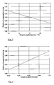
- Figure 3 shows the influence of Ambient temperature to the relative output power of the Gas turbine plant under full load conditions.
- the Decrease in the relative output power of the gas turbine plant visible when the ambient temperature rises.
- Figure 4 finally shows the dependence of the relative Output power of the gas turbine system under full load conditions Change in the pressure of the ambient air caused by Weather conditions or the elevation. From this illustration is can be seen that the relative output power of the gas turbine plant at Decrease in air pressure also drops. This one too Power change depending on the pressure of the ambient air can can be counteracted by switching on the booster levels.
Landscapes
- Engineering & Computer Science (AREA)
- Chemical & Material Sciences (AREA)
- Combustion & Propulsion (AREA)
- Mechanical Engineering (AREA)
- General Engineering & Computer Science (AREA)
- Engine Equipment That Uses Special Cycles (AREA)
- Structures Of Non-Positive Displacement Pumps (AREA)
- Supercharger (AREA)
- Separation By Low-Temperature Treatments (AREA)
Abstract
Description
- Fig. 1
- eine schematische Darstellung einer Gasturbinenanlage gemäß der vorliegenden Erfindung;
- Fig. 2
- eine schematische Darstellung der Verhältnisse zwischen Air-Intake-Booster und Exhaust-Gas-Booster bzgl. der Abhängigkeit von Leistung und Wirkungsgrad der Strömungsmaschine von Druckänderungen;
- Fig. 3
- ein Beispiel für die Abhängigkeit der relativen Ausgangsleistung einer Gasturbinenanlage von der Umgebungstemperatur; und
- Fig. 4
- ein Beispiel für die Abhängigkeit der relativen Ausgangsleistung einer Gasturbinenanlage vom Umgebungsdruck.
Unter einer Gasturbine als konkrete Form einer Strömungsmaschine wird eine Anlage bestehend aus Verdichter, mindestens einer Brennkammer und mindestens einer Turbine verstanden. Eine Gasturbinenanlage schliesst zudem einen Generator zur Stromerzeugung ein.
Unter einer Kombianlage versteht man zunächst die Kopplung eines Gas- und eines Dampfprozesses in Form einer Gasturbinenanlage und einer Dampfturbinenanlage. Die Wärme der Abgase der Turbine der Gasturbinenanlage dient dabei zur Dampferzeugung in einem Abhitzekessel. Der erzeugte Dampf wird mittels der Dampfturbinenanlage zur Stromerzeugung genutzt.
In Analogie zum Air-Intake-Booster 3 kann auch der Exhaust-Gas-Booster 9 zu einer konstruktiven und strömungstechnischen Optimierung des gesamten Abgassystems, d. h. des Abhitzekessels und des Abgaskanals, dienen.
Weiterhin kann durch gezielte Steuerung der Booster-Stufen beispielsweise Standort- und Klimaeinflüssen, unterschiedlichen Brennstoffqualitäten, differenzierten Netzanforderungen u. dgl. Rechnung getragen werden.
Vorzugsweise enthält das vorliegende System eine entsprechende Steuerung 15 für die drehzahlgeregelten Antriebe 13 der Booster-Elemente 12 beider Booster-Stufen 3,9.
| 1 | Ansaugkanal |
| 2 | Verdichter |
| 3 | Erste Booster-Stufe (Air-Intake-Booster) |
| 4 | Brennkammer |
| 5 | Turbine |
| 6 | Generator |
| 7 | Zwischenelement, Abhitzekessel |
| 8 | Abgaskanal |
| 9 | Zweite Booster-Stufe (Exhaust-Gas-Booster) |
| 10 | Bypass (-kamin, -kanal; ansaugluftseitig, abgasseitig) |
| 11 | Klappensystem |
| 12 | Booster-Element |
| 13 | Antrieb (drehzahlgeregelt) |
| 14 | Lüfter |
| 15 | Steuerung von 13 |
| 16 | Lüfterblatt (verstellbar) |
Claims (18)
- Strömungsmaschine mit einem Verdichter (2) und mindestens einer Turbine (5), bei der in einem Ansaugkanal (1) des Verdichters (2) eine erste Booster-Stufe (3) angeordnet ist,
dadurch gekennzeichnet, dass in einem Abgaskanal (8), der sich direkt oder über Zwischenelemente (7) an die Turbine (5) anschließt, oder in einem Bypass(kanal) (10) zu dem Abgaskanal (8) eine zweite Booster-Stufe (9) angeordnet ist. - Strömungsmaschine mit einem Verdichter (2) mit einem Ansaugkanal (1) und mindestens einer Turbine (5), bei der in einem Bypass(kanal) (10) zu dem Ansaugkanal (1) eine erste Booster-Stufe (3) und
in einem Abgaskanal (8), der sich direkt oder über Zwischenelemente (7) an die Turbine (5) anschließt, oder in einem Bypass(kanal) (10) zu dem Abgaskanal (8) eine zweite Booster-Stufe (9) angeordnet ist. - Strömungsmaschine nach Anspruch 1 oder 2,
dadurch gekennzeichnet, dass die erste Booster-Stufe (3) und/oder die zweite Booster-Stufe (9) aus einem oder mehreren parallel oder in Reihe angeordneten Booster-Elementen (12) mit Lüftern (14) besteht. - Strömungsmaschine nach Anspruch 3,
dadurch gekennzeichnet, dass die Booster-Elemente (12) Antriebe (13) aufweisen, die als Niederspannungsantriebe ausgelegt sind. - Strömungsmaschine nach Anspruch 3 oder 4,
dadurch gekennzeichnet, dass die Lüfter (14) der Booster-Elemente (12) durch einen drehzahlgeregelten Antrieb (13) angetrieben werden. - Strömungsmaschine nach einem der Ansprüche 3 bis 5,
dadurch gekennzeichnet, dass die Lüfter (14) der Booster-Elemente (12) mit verstellbaren Lüfterblättern (16) ausgerüstet sind. - Strömungsmaschine nach Anspruch 1 bis 6,
dadurch gekennzeichnet, dass zwischen dem Abgaskanal (8) und der Turbine (5) ein Wärmerückgewinnungssystem, insbesondere ein Abhitzekessel (7), als Zwischenelement vorgesehen ist. - Strömungsmaschine nach einem der Ansprüche 1 bis 7,
dadurch gekennzeichnet, dass die erste Booster-Stufe (3) und die zweite Booster-Stufe (9) zur Optimierung des gesamten Ansaugbereiches bis zum Eintritt der Ansaugluft in den Verdichter bzw. des gesamten Abgasbereiches ab dem Austritt der Abgase aus der Turbine sowohl hinsichtlich der konstruktiven Ausführung als auch der Strömungstechnik ausgelegt sind. - Strömungsmaschine nach einem der Ansprüche 1 bis 8,
dadurch gekennzeichnet, dass die Höhe des Abgaskanals (8) gegenüber einer Strömungsmaschine ohne zweite Booster-Stufe (9) verringert ist, wobei die zweite Booster-Stufe (9) zur Kompensation der aus der Verringerung der Höhe des Abgaskanals (8) veränderten Auftriebsbedingungen ausgelegt ist. - Verfahren zum Betrieb einer Strömungsmaschine nach einem oder mehreren der vorhergehenden Ansprüche, bei dem die erste Booster-Stufe (3) und die zweite Booster-Stufe (9) in Abhängigkeit von den konkreten Betriebsbedingungen einzeln oder in Kombination betrieben werden.
- Verfahren nach Anspruch 10,
dadurch gekennzeichnet, dass bei einem hohen Leistungsbedarf bzw. bei der Notwendigkeit zur Bereitstellung von Reserveleistung die erste Booster-Stufe (3) und/oder die zweite Booster-Stufe (9) betrieben wird. - Verfahren nach Anspruch 10,
dadurch gekennzeichnet, dass bei Notwendigkeit des Betriebes der Strömungsmaschine zum Zwecke der Frequenzregelung die erste Booster-Stufe (3) und/oder die zweite Booster-Stufe (9) betrieben wird. - Verfahren nach Anspruch 10,
dadurch gekennzeichnet, dass vor dem Anfahren und/oder während des Anfahrens der Strömungsmaschine die erste Booster-Stufe (3) und/oder die zweite Booster-Stufe (9) zum Zwecke des Spülens der Anlage betrieben wird. - Verfahren nach Anspruch 10,
dadurch gekennzeichnet, dass während des Abfahrens und/oder nach dem Abfahren der Strömungsmaschine die erste Booster-Stufe (3) und/oder die zweite Booster-Stufe (9) zum Zwecke des Kühlens der Anlage betrieben wird. - Verfahren nach Anspruch 10,
dadurch gekennzeichnet, dass während des Anfahrens bzw. während einer Leistungssteigerung der Strömungsmaschine die erste Booster-Stufe (3) und/oder die zweite Booster-Stufe (9) zum Zwecke der Realisierung eines erhöhten Leistungsgradienten der Anlage betrieben wird. - Verfahren nach Anspruch 10,
dadurch gekennzeichnet, dass während des Anfahrens bzw. während einer Leistungssteigerung der Strömungsmaschine die erste Booster-Stufe (3) und/oder die zweite Booster-Stufe (9) zum Zwecke eines schonenderen Betriebes der Anlage bei gleichem Leistungsgradienten wie ohne Betrieb der Booster-Stufen (3,9) betrieben werden. - Verfahren nach Anspruch 10,
dadurch gekennzeichnet, dass bei Betrieb der ersten Booster-Stufe (3) und/oder der zweiten Booster-Stufe (9) die Feuerungsleistung zurückgenommen wird, um die gleiche Ausgangsleistung der Strömungsmaschine bereitzustellen wie ohne Betrieb der ersten Booster-Stufe (3) und/oder der zweiten Booster-Stufe (9). - Verfahren nach Anspruch 10,
dadurch gekennzeichnet, dass bei Notwendigkeit der Verbesserung der Emissionsbedingungen die zweite Booster-Stufe (9) zur Erhöhung der Austrittsgeschwindigkeit und damit des Auftriebs der aus dem Abgaskanal (8) ausströmenden Abgase betrieben wird.
Applications Claiming Priority (2)
| Application Number | Priority Date | Filing Date | Title |
|---|---|---|---|
| DE10064263A DE10064263A1 (de) | 2000-12-22 | 2000-12-22 | Strömungsmaschine und Verfahren zum Betrieb |
| DE10064263 | 2000-12-22 |
Publications (3)
| Publication Number | Publication Date |
|---|---|
| EP1219801A2 true EP1219801A2 (de) | 2002-07-03 |
| EP1219801A3 EP1219801A3 (de) | 2005-09-07 |
| EP1219801B1 EP1219801B1 (de) | 2009-10-21 |
Family
ID=7668436
Family Applications (1)
| Application Number | Title | Priority Date | Filing Date |
|---|---|---|---|
| EP01128786A Expired - Lifetime EP1219801B1 (de) | 2000-12-22 | 2001-12-04 | Gasturbinenanlage |
Country Status (4)
| Country | Link |
|---|---|
| US (1) | US6786034B2 (de) |
| EP (1) | EP1219801B1 (de) |
| AT (1) | ATE446443T1 (de) |
| DE (2) | DE10064263A1 (de) |
Cited By (3)
| Publication number | Priority date | Publication date | Assignee | Title |
|---|---|---|---|---|
| EP2067940A2 (de) * | 2007-09-07 | 2009-06-10 | ALSTOM Technology Ltd | Verfahren zum Betrieb eines Kombikraftwerks sowie Kombikfartwerk zur Durchführung des Verfahrens |
| EP2631022A1 (de) | 2012-02-21 | 2013-08-28 | Newfrey LLC | Matrize für eine Vorrichtung zum Setzen von Stanznieten |
| WO2021115671A1 (de) * | 2019-12-13 | 2021-06-17 | Siemens Energy Global GmbH & Co. KG | Kesselspülen |
Families Citing this family (14)
| Publication number | Priority date | Publication date | Assignee | Title |
|---|---|---|---|---|
| EP1451458B1 (de) * | 2001-10-01 | 2006-07-19 | Camfil Ab | Anorndung bei gasturbine |
| DE102004028531A1 (de) | 2004-06-11 | 2006-01-05 | Alstom Technology Ltd | Verfahren zum Betrieb einer Kraftwerksanlage, und Kraftwerksanlage |
| GB2524582B (en) * | 2014-03-28 | 2016-07-20 | Mitsubishi Hitachi Power Sys | Combined cycle gas turbine plant |
| US10030558B2 (en) | 2015-06-29 | 2018-07-24 | General Electric Company | Power generation system exhaust cooling |
| US9840953B2 (en) | 2015-06-29 | 2017-12-12 | General Electric Company | Power generation system exhaust cooling |
| US10087801B2 (en) * | 2015-06-29 | 2018-10-02 | General Electric Company | Power generation system exhaust cooling |
| US9850818B2 (en) | 2015-06-29 | 2017-12-26 | General Electric Company | Power generation system exhaust cooling |
| US9850794B2 (en) * | 2015-06-29 | 2017-12-26 | General Electric Company | Power generation system exhaust cooling |
| US9938874B2 (en) | 2015-06-29 | 2018-04-10 | General Electric Company | Power generation system exhaust cooling |
| US9856768B2 (en) | 2015-06-29 | 2018-01-02 | General Electric Company | Power generation system exhaust cooling |
| US10077694B2 (en) | 2015-06-29 | 2018-09-18 | General Electric Company | Power generation system exhaust cooling |
| US10060316B2 (en) | 2015-06-29 | 2018-08-28 | General Electric Company | Power generation system exhaust cooling |
| US10215070B2 (en) | 2015-06-29 | 2019-02-26 | General Electric Company | Power generation system exhaust cooling |
| US10316759B2 (en) | 2016-05-31 | 2019-06-11 | General Electric Company | Power generation system exhaust cooling |
Citations (1)
| Publication number | Priority date | Publication date | Assignee | Title |
|---|---|---|---|---|
| US3979903A (en) | 1974-08-01 | 1976-09-14 | General Electric Company | Gas turbine engine with booster stage |
Family Cites Families (6)
| Publication number | Priority date | Publication date | Assignee | Title |
|---|---|---|---|---|
| FR2228949B1 (de) * | 1973-05-08 | 1977-02-11 | Snecma | |
| US4222234A (en) * | 1977-07-25 | 1980-09-16 | General Electric Company | Dual fan engine for VTOL pitch control |
| GB1557817A (en) * | 1977-08-25 | 1979-12-12 | Penny Turbines Ltd Noel | Gas turbine ducted fan engines having expansion to sub atmospheric pressure |
| CH630702A5 (de) * | 1978-04-26 | 1982-06-30 | Sulzer Ag | Anlage zum erzeugen von druckgas. |
| GB9225949D0 (en) * | 1992-12-11 | 1993-02-03 | British Gas Plc | Combined heat and power apparatus |
| US5775092A (en) * | 1995-11-22 | 1998-07-07 | General Electric Company | Variable size gas turbine engine |
-
2000
- 2000-12-22 DE DE10064263A patent/DE10064263A1/de not_active Withdrawn
-
2001
- 2001-12-04 AT AT01128786T patent/ATE446443T1/de not_active IP Right Cessation
- 2001-12-04 DE DE50115188T patent/DE50115188D1/de not_active Expired - Lifetime
- 2001-12-04 EP EP01128786A patent/EP1219801B1/de not_active Expired - Lifetime
- 2001-12-05 US US10/002,149 patent/US6786034B2/en not_active Expired - Lifetime
Patent Citations (1)
| Publication number | Priority date | Publication date | Assignee | Title |
|---|---|---|---|---|
| US3979903A (en) | 1974-08-01 | 1976-09-14 | General Electric Company | Gas turbine engine with booster stage |
Cited By (7)
| Publication number | Priority date | Publication date | Assignee | Title |
|---|---|---|---|---|
| EP2067940A2 (de) * | 2007-09-07 | 2009-06-10 | ALSTOM Technology Ltd | Verfahren zum Betrieb eines Kombikraftwerks sowie Kombikfartwerk zur Durchführung des Verfahrens |
| US8146366B2 (en) | 2007-09-07 | 2012-04-03 | Alstom Technology Ltd. | Method for operating a combined-cycle power plant, and combined-cycle power plant useful for carrying out the method |
| EP2067940A3 (de) * | 2007-09-07 | 2013-06-19 | Alstom Technology Ltd | Verfahren zum Betrieb eines Kombikraftwerks sowie Kombikfartwerk zur Durchführung des Verfahrens |
| US8516787B2 (en) | 2007-09-07 | 2013-08-27 | Alstom Technology Ltd. | Combined-cycle power plant having a once-through cooler |
| EP2067940B1 (de) | 2007-09-07 | 2019-10-02 | General Electric Technology GmbH | Verfahren zum Betrieb eines Kombikraftwerks sowie Kombikraftwerk zur Durchführung des Verfahrens |
| EP2631022A1 (de) | 2012-02-21 | 2013-08-28 | Newfrey LLC | Matrize für eine Vorrichtung zum Setzen von Stanznieten |
| WO2021115671A1 (de) * | 2019-12-13 | 2021-06-17 | Siemens Energy Global GmbH & Co. KG | Kesselspülen |
Also Published As
| Publication number | Publication date |
|---|---|
| DE10064263A1 (de) | 2002-07-04 |
| DE50115188D1 (de) | 2009-12-03 |
| EP1219801A3 (de) | 2005-09-07 |
| EP1219801B1 (de) | 2009-10-21 |
| US20020092304A1 (en) | 2002-07-18 |
| US6786034B2 (en) | 2004-09-07 |
| ATE446443T1 (de) | 2009-11-15 |
Similar Documents
| Publication | Publication Date | Title |
|---|---|---|
| EP1219801B1 (de) | Gasturbinenanlage | |
| EP2071157B1 (de) | Verfahren zur Regelung einer Gasturbine in einem Kraftwerk | |
| DE60133629T2 (de) | Verfahren zum betrieb einer gasturbine mit verstellbaren leitschaufeln | |
| EP1711690B1 (de) | Gasturbine, insbesondere flugtriebwerk | |
| DE69635324T2 (de) | Gasturbinensystem und Herstellungsverfahren | |
| EP0718470A2 (de) | Verfahren zum Betrieb einer Gasturbogruppe | |
| DE19824766C2 (de) | Gasturbine sowie Verfahren zur Kühlung einer Turbinenstufe | |
| WO2001065095A1 (de) | Kühlluftsystem | |
| EP2011963B1 (de) | Verfahren zum Betrieb einer Gasturbine mit Axialschubausgleich | |
| EP1914407B1 (de) | Verfahren zum Betrieb einer Gasturbinenanlage | |
| EP2340397B1 (de) | Brennereinsatz für eine gasturbinenbrennkammer und gasturbine | |
| DE2831802A1 (de) | Gasturbinentriebwerk und verfahren zu dessen betrieb | |
| DE102007025006A1 (de) | Doppelwellen-Gasturbine | |
| DE19501471A1 (de) | Turbine, insbesondere Gasturbine | |
| EP0646705A1 (de) | Verfahren zur Erstellung eines Teillastbetriebes bei einer Gasturbogruppe | |
| DE3720578C2 (de) | Gasturbinen-Mantelstrom-Triebwerk mit veränderbarem Nebenstromverhältnis | |
| EP1006644A2 (de) | Gasgekühlte elektrische Maschine mit einem Axialventilator | |
| EP2407652A1 (de) | Gasturbine mit einem Sekundärluftsystem und Verfahren zum Betreiben einer solchen Gasturbine | |
| WO2014033220A1 (de) | Kühlverfahren zum betreiben einer gasturbine | |
| CH709266B1 (de) | Turbinenschaufel und Verfahren zum Auswuchten eines Spitzendeckbandes einer Turbinenschaufel und Gasturbine. | |
| EP0718483A2 (de) | Dampfeinspritzgasturbine | |
| DE2132334A1 (de) | Regelvorrichtung fuer ein Verwandlungstriebwerk | |
| EP1262637A1 (de) | Verfahren zum Betrieben eines Gasturbinenkraftwerks sowie Gasturbinenkraftwerk | |
| EP0296440B1 (de) | Dampfturbine für Teillastbetrieb | |
| DE4442936A1 (de) | Gasturbine |
Legal Events
| Date | Code | Title | Description |
|---|---|---|---|
| PUAI | Public reference made under article 153(3) epc to a published international application that has entered the european phase |
Free format text: ORIGINAL CODE: 0009012 |
|
| AK | Designated contracting states |
Kind code of ref document: A2 Designated state(s): AT BE CH CY DE DK ES FI FR GB GR IE IT LI LU MC NL PT SE TR |
|
| AX | Request for extension of the european patent |
Free format text: AL;LT;LV;MK;RO;SI |
|
| RAP1 | Party data changed (applicant data changed or rights of an application transferred) |
Owner name: ALSTOM (SWITZERLAND) LTD |
|
| RAP1 | Party data changed (applicant data changed or rights of an application transferred) |
Owner name: ALSTOM TECHNOLOGY LTD |
|
| PUAL | Search report despatched |
Free format text: ORIGINAL CODE: 0009013 |
|
| AK | Designated contracting states |
Kind code of ref document: A3 Designated state(s): AT BE CH CY DE DK ES FI FR GB GR IE IT LI LU MC NL PT SE TR |
|
| AX | Request for extension of the european patent |
Extension state: AL LT LV MK RO SI |
|
| RIC1 | Information provided on ipc code assigned before grant |
Ipc: 7F 02C 6/00 B Ipc: 7F 02C 3/36 A Ipc: 7F 02K 3/065 B |
|
| 17P | Request for examination filed |
Effective date: 20060217 |
|
| AKX | Designation fees paid |
Designated state(s): AT BE CH CY DE DK ES FI FR GB GR IE IT LI LU MC NL PT SE TR |
|
| RTI1 | Title (correction) |
Free format text: GAS TURBINE POWER PLANT |
|
| GRAP | Despatch of communication of intention to grant a patent |
Free format text: ORIGINAL CODE: EPIDOSNIGR1 |
|
| GRAS | Grant fee paid |
Free format text: ORIGINAL CODE: EPIDOSNIGR3 |
|
| GRAA | (expected) grant |
Free format text: ORIGINAL CODE: 0009210 |
|
| AK | Designated contracting states |
Kind code of ref document: B1 Designated state(s): AT BE CH CY DE DK ES FI FR GB GR IE IT LI LU MC NL PT SE TR |
|
| REG | Reference to a national code |
Ref country code: GB Ref legal event code: FG4D Free format text: NOT ENGLISH |
|
| REG | Reference to a national code |
Ref country code: CH Ref legal event code: EP |
|
| REG | Reference to a national code |
Ref country code: IE Ref legal event code: FG4D |
|
| REF | Corresponds to: |
Ref document number: 50115188 Country of ref document: DE Date of ref document: 20091203 Kind code of ref document: P |
|
| NLV1 | Nl: lapsed or annulled due to failure to fulfill the requirements of art. 29p and 29m of the patents act | ||
| PG25 | Lapsed in a contracting state [announced via postgrant information from national office to epo] |
Ref country code: ES Free format text: LAPSE BECAUSE OF FAILURE TO SUBMIT A TRANSLATION OF THE DESCRIPTION OR TO PAY THE FEE WITHIN THE PRESCRIBED TIME-LIMIT Effective date: 20100201 Ref country code: FI Free format text: LAPSE BECAUSE OF FAILURE TO SUBMIT A TRANSLATION OF THE DESCRIPTION OR TO PAY THE FEE WITHIN THE PRESCRIBED TIME-LIMIT Effective date: 20091021 Ref country code: SE Free format text: LAPSE BECAUSE OF FAILURE TO SUBMIT A TRANSLATION OF THE DESCRIPTION OR TO PAY THE FEE WITHIN THE PRESCRIBED TIME-LIMIT Effective date: 20091021 Ref country code: PT Free format text: LAPSE BECAUSE OF FAILURE TO SUBMIT A TRANSLATION OF THE DESCRIPTION OR TO PAY THE FEE WITHIN THE PRESCRIBED TIME-LIMIT Effective date: 20100222 |
|
| REG | Reference to a national code |
Ref country code: IE Ref legal event code: FD4D |
|
| BERE | Be: lapsed |
Owner name: ALSTOM TECHNOLOGY LTD Effective date: 20091231 |
|
| PG25 | Lapsed in a contracting state [announced via postgrant information from national office to epo] |
Ref country code: DK Free format text: LAPSE BECAUSE OF FAILURE TO SUBMIT A TRANSLATION OF THE DESCRIPTION OR TO PAY THE FEE WITHIN THE PRESCRIBED TIME-LIMIT Effective date: 20091021 Ref country code: MC Free format text: LAPSE BECAUSE OF NON-PAYMENT OF DUE FEES Effective date: 20100701 Ref country code: IE Free format text: LAPSE BECAUSE OF FAILURE TO SUBMIT A TRANSLATION OF THE DESCRIPTION OR TO PAY THE FEE WITHIN THE PRESCRIBED TIME-LIMIT Effective date: 20091021 |
|
| REG | Reference to a national code |
Ref country code: CH Ref legal event code: PL |
|
| PLBE | No opposition filed within time limit |
Free format text: ORIGINAL CODE: 0009261 |
|
| STAA | Information on the status of an ep patent application or granted ep patent |
Free format text: STATUS: NO OPPOSITION FILED WITHIN TIME LIMIT |
|
| REG | Reference to a national code |
Ref country code: FR Ref legal event code: ST Effective date: 20100831 |
|
| 26N | No opposition filed |
Effective date: 20100722 |
|
| PG25 | Lapsed in a contracting state [announced via postgrant information from national office to epo] |
Ref country code: FR Free format text: LAPSE BECAUSE OF NON-PAYMENT OF DUE FEES Effective date: 20091231 Ref country code: GR Free format text: LAPSE BECAUSE OF FAILURE TO SUBMIT A TRANSLATION OF THE DESCRIPTION OR TO PAY THE FEE WITHIN THE PRESCRIBED TIME-LIMIT Effective date: 20100122 Ref country code: LI Free format text: LAPSE BECAUSE OF NON-PAYMENT OF DUE FEES Effective date: 20091231 Ref country code: BE Free format text: LAPSE BECAUSE OF NON-PAYMENT OF DUE FEES Effective date: 20091231 Ref country code: CH Free format text: LAPSE BECAUSE OF NON-PAYMENT OF DUE FEES Effective date: 20091231 |
|
| PG25 | Lapsed in a contracting state [announced via postgrant information from national office to epo] |
Ref country code: IT Free format text: LAPSE BECAUSE OF FAILURE TO SUBMIT A TRANSLATION OF THE DESCRIPTION OR TO PAY THE FEE WITHIN THE PRESCRIBED TIME-LIMIT Effective date: 20091021 |
|
| PG25 | Lapsed in a contracting state [announced via postgrant information from national office to epo] |
Ref country code: LU Free format text: LAPSE BECAUSE OF NON-PAYMENT OF DUE FEES Effective date: 20091204 |
|
| PG25 | Lapsed in a contracting state [announced via postgrant information from national office to epo] |
Ref country code: AT Free format text: LAPSE BECAUSE OF NON-PAYMENT OF DUE FEES Effective date: 20091204 |
|
| PG25 | Lapsed in a contracting state [announced via postgrant information from national office to epo] |
Ref country code: TR Free format text: LAPSE BECAUSE OF FAILURE TO SUBMIT A TRANSLATION OF THE DESCRIPTION OR TO PAY THE FEE WITHIN THE PRESCRIBED TIME-LIMIT Effective date: 20091021 |
|
| PG25 | Lapsed in a contracting state [announced via postgrant information from national office to epo] |
Ref country code: CY Free format text: LAPSE BECAUSE OF FAILURE TO SUBMIT A TRANSLATION OF THE DESCRIPTION OR TO PAY THE FEE WITHIN THE PRESCRIBED TIME-LIMIT Effective date: 20091021 |
|
| PG25 | Lapsed in a contracting state [announced via postgrant information from national office to epo] |
Ref country code: NL Free format text: LAPSE BECAUSE OF FAILURE TO SUBMIT A TRANSLATION OF THE DESCRIPTION OR TO PAY THE FEE WITHIN THE PRESCRIBED TIME-LIMIT Effective date: 20091021 |
|
| REG | Reference to a national code |
Ref country code: DE Ref legal event code: R082 Ref document number: 50115188 Country of ref document: DE Representative=s name: ROESLER, UWE, DIPL.-PHYS.UNIV., DE Ref country code: DE Ref legal event code: R081 Ref document number: 50115188 Country of ref document: DE Owner name: GENERAL ELECTRIC TECHNOLOGY GMBH, CH Free format text: FORMER OWNER: ALSTOM TECHNOLOGY LTD., BADEN, CH Ref country code: DE Ref legal event code: R081 Ref document number: 50115188 Country of ref document: DE Owner name: ANSALDO ENERGIA IP UK LIMITED, GB Free format text: FORMER OWNER: ALSTOM TECHNOLOGY LTD., BADEN, CH |
|
| PGFP | Annual fee paid to national office [announced via postgrant information from national office to epo] |
Ref country code: GB Payment date: 20161222 Year of fee payment: 16 Ref country code: DE Payment date: 20161213 Year of fee payment: 16 |
|
| REG | Reference to a national code |
Ref country code: DE Ref legal event code: R082 Ref document number: 50115188 Country of ref document: DE Representative=s name: ROESLER, UWE, DIPL.-PHYS.UNIV., DE Ref country code: DE Ref legal event code: R081 Ref document number: 50115188 Country of ref document: DE Owner name: ANSALDO ENERGIA IP UK LIMITED, GB Free format text: FORMER OWNER: GENERAL ELECTRIC TECHNOLOGY GMBH, BADEN, CH |
|
| REG | Reference to a national code |
Ref country code: GB Ref legal event code: 732E Free format text: REGISTERED BETWEEN 20170824 AND 20170830 |
|
| REG | Reference to a national code |
Ref country code: DE Ref legal event code: R119 Ref document number: 50115188 Country of ref document: DE |
|
| GBPC | Gb: european patent ceased through non-payment of renewal fee |
Effective date: 20171204 |
|
| PG25 | Lapsed in a contracting state [announced via postgrant information from national office to epo] |
Ref country code: DE Free format text: LAPSE BECAUSE OF NON-PAYMENT OF DUE FEES Effective date: 20180703 |
|
| PG25 | Lapsed in a contracting state [announced via postgrant information from national office to epo] |
Ref country code: GB Free format text: LAPSE BECAUSE OF NON-PAYMENT OF DUE FEES Effective date: 20171204 |