EP1219763A2 - Design analysis method of earthquake-proof reinforcement structure, and storage medium - Google Patents
Design analysis method of earthquake-proof reinforcement structure, and storage medium Download PDFInfo
- Publication number
- EP1219763A2 EP1219763A2 EP01128474A EP01128474A EP1219763A2 EP 1219763 A2 EP1219763 A2 EP 1219763A2 EP 01128474 A EP01128474 A EP 01128474A EP 01128474 A EP01128474 A EP 01128474A EP 1219763 A2 EP1219763 A2 EP 1219763A2
- Authority
- EP
- European Patent Office
- Prior art keywords
- earthquake
- load
- proof reinforcement
- reinforcement structure
- ultimate
- Prior art date
- Legal status (The legal status is an assumption and is not a legal conclusion. Google has not performed a legal analysis and makes no representation as to the accuracy of the status listed.)
- Withdrawn
Links
Images






Classifications
-
- E—FIXED CONSTRUCTIONS
- E04—BUILDING
- E04H—BUILDINGS OR LIKE STRUCTURES FOR PARTICULAR PURPOSES; SWIMMING OR SPLASH BATHS OR POOLS; MASTS; FENCING; TENTS OR CANOPIES, IN GENERAL
- E04H9/00—Buildings, groups of buildings or shelters adapted to withstand or provide protection against abnormal external influences, e.g. war-like action, earthquake or extreme climate
-
- E—FIXED CONSTRUCTIONS
- E04—BUILDING
- E04G—SCAFFOLDING; FORMS; SHUTTERING; BUILDING IMPLEMENTS OR AIDS, OR THEIR USE; HANDLING BUILDING MATERIALS ON THE SITE; REPAIRING, BREAKING-UP OR OTHER WORK ON EXISTING BUILDINGS
- E04G23/00—Working measures on existing buildings
- E04G23/02—Repairing, e.g. filling cracks; Restoring; Altering; Enlarging
- E04G23/0218—Increasing or restoring the load-bearing capacity of building construction elements
-
- G—PHYSICS
- G06—COMPUTING OR CALCULATING; COUNTING
- G06F—ELECTRIC DIGITAL DATA PROCESSING
- G06F30/00—Computer-aided design [CAD]
-
- E—FIXED CONSTRUCTIONS
- E04—BUILDING
- E04B—GENERAL BUILDING CONSTRUCTIONS; WALLS, e.g. PARTITIONS; ROOFS; FLOORS; CEILINGS; INSULATION OR OTHER PROTECTION OF BUILDINGS
- E04B1/00—Constructions in general; Structures which are not restricted either to walls, e.g. partitions, or floors or ceilings or roofs
- E04B1/18—Structures comprising elongated load-supporting parts, e.g. columns, girders, skeletons
- E04B1/24—Structures comprising elongated load-supporting parts, e.g. columns, girders, skeletons the supporting parts consisting of metal
- E04B1/2403—Connection details of the elongated load-supporting parts
- E04B2001/2463—Connections to foundations
-
- G—PHYSICS
- G06—COMPUTING OR CALCULATING; COUNTING
- G06F—ELECTRIC DIGITAL DATA PROCESSING
- G06F2113/00—Details relating to the application field
- G06F2113/14—Pipes
Definitions
- the present invention relates to a design analysis method of an earthquake-proof reinforcement structure for a pipe rack which supports an energy transport pipe used in a plant such as a natural gas (LNG) stock facility, and a storage medium which stores a program module for causing a computer to execute the analysis.
- a plant such as a natural gas (LNG) stock facility
- LNG natural gas
- members such as beams, columns, or braces are selected without taking an ultimate load (true strength) until the pipe rack finally breaks into consideration. That is, for the relationship between a structure and an external force that the structure should withstand, a member with or without a sufficient strength may be selected, and no quantitative evaluation is reflected at the stage of design.
- Conventional strength design for a foundation ensures a sufficient safety factor against an axial force (a load that acts in the axial direction of a member), though the safety factor against a bending moment has no sufficient margin as compared to that for an axial force.
- the earthquake-proof reinforcement method of applying a cover plate to a column or beam can be preferably used.
- the allowable stress of a foundation is designed with little margin, the method of simply reinforcing a column or beam using a cover plate is not preferable.
- members such as beams, columns, or braces are selected without taking an ultimate load (true strength) until the pipe rack finally breaks into consideration. That is, for the relationship between a rack structure and a load that the structure should withstand, members having a sufficient strength and members without any sufficient strength may be consequently selected and mixed, and quantitative evaluation for load condition and member selection in consideration of situations until the entire pipe rack collapses is not reflected at the stage of design.
- an earthquake-proof reinforcement method in reinforcing the base of a column member standing on the foundation of a pipe rack by a concrete member with pedestal foundation, an earthquake-proof reinforcement structure using concrete with pedestal foundation for a column member is applied to the pipe rack, in which a damper portion is provided between the column base and the concrete member with pedestal foundation, and a bending moment generated in the base by an external force is reduced by the damper portion such that it is hardly transmitted to the foundation, thereby reducing the bending moment that the foundation member takes a share.
- a load factor semiconductor intensity
- ⁇ /f allowable stress intensity ratio
- a design analysis method of an earthquake-proof reinforcement structure and storage medium according to the present invention are mainly characterized by the following arrangements.
- a design analysis method of an earthquake-proof reinforcement structure characterized by comprising:
- the maximum value of the allowable stress intensity ratio is preferably 1.0.
- the ductility factor ratio in earthquake-proof reinforcement having a damper portion arranged between a base of a column member and a reinforcing member using concrete with pedestal foundation in the earthquake-proof reinforcement structure is preferably not less than 3.0.
- a load of an object supported by the earthquake-proof reinforcement structure is used as a condition for member selection.
- the specifying step for an earthquake-proof reinforcement structure formed from a plurality of types of members, ultimate loads specified for the respective members are compared, and a minimum ultimate load of the ultimate loads is specified as the ultimate load of the earthquake-proof reinforcement structure.
- the specifying step for an earthquake-proof reinforcement structure formed from a main member and a reinforcing member for reinforcing the main member, ultimate loads specified for the respective members are compared, and when the ultimate load of the main member is larger than that of the reinforcing member, the ultimate load of the main member is specified as the ultimate load of the earthquake-proof reinforcement structure.
- the main member comprises a beam or column member
- the reinforcing member comprises a brace member
- a storage medium which stores a program module for causing a computer to execute a design analysis method of an earthquake-proof reinforcement structure comprising:
- the maximum value of the allowable stress intensity ratio is preferably 1.0.
- the ductility factor ratio in earthquake-proof reinforcement having a damper portion arranged between a base of a column member and a reinforcing member using concrete with pedestal foundation in the earthquake-proof reinforcement structure is preferably not less than 3.
- selection processing of the member is executed using a load of an object supported by the earthquake-proof reinforcement structure as a condition for member selection.
- the specifying module for an earthquake-proof reinforcement structure formed from a plurality of types of members, ultimate loads specified for the respective members are compared, and a minimum ultimate load of the ultimate loads is specified as the ultimate load of the earthquake-proof reinforcement structure.
- the specifying module for an earthquake-proof reinforcement structure formed from a main member and a reinforcing member for reinforcing the main member, ultimate loads specified for the respective members are compared, and when the ultimate load of the main member is larger than that of the reinforcing member, the ultimate load of the main member is specified as the ultimate load of the earthquake-proof reinforcement structure.
- a design analysis method of an earthquake-proof reinforcement structure comprising the steps of:
- Figs. 1A to 1C are views showing the entire structure of a pipe rack 1 before reinforcement.
- Fig. 1A is a plan view of the pipe rack 1 formed from steel columns 2a (e.g., H steel)
- Fig. 1B is a front view of the pipe rack 1
- Fig. 1C is a side view of the pipe rack 1.
- Each steel column 2a stands on a foundation 3, as shown in Figs. 1B and 1C.
- a beam 2b is fixed between two columns 2a, which are reinforced by brace members 2c.
- Fig. 2 is an enlarged view showing a lower-end side surface of an unreinforced column base of the pipe rack 1.
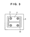
- Fig. 3 is a view showing the attachment portion of the lower end of the column base shown in Fig. 2 when viewed from the direction of the arrow in Fig. 2.
- Figs. 2 and 3 show a state wherein the unreinforced steel column 2a is welded to a base plate 4 and connected to the foundation 3 by anchor bolts 5.
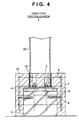
- Fig. 4 is an enlarged view of the column base of the pipe rack 1, which is reinforced by a reinforcement structure using concrete with pedestal foundation.
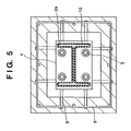
- Fig. 5 is a sectional view of the column base of the pipe rack 1, which is reinforced by the reinforcement structure using concrete with pedestal foundation, when viewed from the direction of the arrow in Fig. 4.
- a procedure of forming the earthquake-proof reinforcement structure (concrete portion 12 with pedestal foundation) on the foundation of the pipe rack will be described below with reference to Fig. 4.
- the concrete portion 12 with pedestal foundation is formed by placing anchor bolts 9 for fixing the concrete portion 12 with pedestal foundation to the foundation 3, and tops 8 of reinforcement and hoop iron rod 6 arranged around the foundation 3, then arranging a form for forming a predetermined gap 10 around the steel column 2a, and finally pouring concrete.
- the form buried around the steel column 2a is removed to form the gap 10 around the steel column 2a.
- the thus obtained gap 10 is filled with a predetermined selected filler (e.g., vibration isolating rubber), thereby forming a reinforcement structure using concrete with pedestal foundation.
- a predetermined selected filler e.g., vibration isolating rubber
- a static loading test was conducted by applying a static load to a rack having no earthquake-proof reinforcement structure (to be referred to as "model A” hereinafter) and a rack having an earthquake-proof reinforcement structure (to be referred to as “model B” hereinafter) to grasp the strength (ultimate strength) beyond the yield point of members such as a beam, brace, and column.
- Fig. 6 is a view showing the set positions of wire strain gauges 13a to 18a set at the column base of the pipe rack 1 used for the earthquake-proof test before reinforcement.
- Fig. 7 is a view showing the set positions of wire strain gauges 13b to 18b set at the column base of the pipe rack 1 used for an earthquake-proof test after reinforcement.
- a static load P is horizontally applied to the beams of model A, as shown in Fig. 1B, and a displacement generated when the load P is gradually increased is measured by the strain gauges.
- the load P is also applied to the same position of model B.
- Figs. 8A and 8B show load-displacement curves of the models A and B obtained by the static loading test.
- stress on each member was gradually increased by the load, and the anchor bolts exceeded the yield point at a load of 25 (kN) (point A 1 in Fig. 8A) and entered a plastic region at a load of 58 (kN) (point B 1 in Fig. 8A).
- the anchor bolts caused ductile fracture at a load of 67 (kN).
- This point is regarded as the collapse point of model A (point C 1 in Fig. 8A). It was confirmed that the ultimate strength of the pipe rack having no earthquake-proof reinforcement structure was determined by the strength of the anchor bolts.
- model B having an earthquake-proof reinforcement structure it was confirmed that the members exceeded the yield point due to loading in the order of the compression-side braces and the beams and columns in the loading direction.
- the compression braces exceeded the plastic region at a load of 160 (kN) (point A 2 in Fig. 8B). After that, as loading was continued, only displacement increased, and the braces completely buckled at a load of 170 (kN). Since the strength of the anchor bolts was increased by concrete with pedestal foundation on the pedestal foundation (Fig. 4), and the columns and beams were reinforced by plates, the compression-side braces buckled first. The braces ruptured at a displacement of 142 (mm) (point C 2 in Fig. 8B). This is the collapse point of model B.
- the yield point is not conspicuous for model A (Fig. 8A) having no earthquake-proof reinforcement structure, though the yield point is conspicuous for the rack having the earthquake-proof reinforcement structure (Fig. 8B), i.e., the characteristic until the final rupture is obviously different from Fig. 8A.
- the ratio of ductility factors will be referred to as a "ductility factor ratio".
- the ductility factor ratio of a structure having an earthquake-proof reinforcement structure means a deformation magnification, for a structure having no reinforcement structure, at which the structure can deform (including both the elastic region and plastic deformation region). That the ductility factor ratio increases to three times physically means that a three-times energy (the area of a portion surrounded by the load-displacement curve) is required until the structure is deformed by a load and collapses, i.e., the difficulty in collapse of the structure increases to three times.
- Figs. 8A and 8B show the displacements obtained by a static load.
- a displacement by a dynamically applied vibration is smaller than the displacement by the static loading test. This is because an eccentric moment acts on each member due to the dynamically applied vibration to generate a stress loss.
- a static load is primarily taken into consideration.
- a damper portion 10 that forms a gap of about 10 to 15 mm is formed around the column member 2a, and the damper portion 10 is filled with a filler which has a high compression strength, expands/shrinks little, and can absorb stress due to bending deformation and, more specifically, an asphalt mastic molded strip plate (cushioning material) serving as a strip material for a concrete structure.
- a filler which has a high compression strength, expands/shrinks little, and can absorb stress due to bending deformation and, more specifically, an asphalt mastic molded strip plate (cushioning material) serving as a strip material for a concrete structure.
- the filler is not limited to the above-described material, and any other material which elastically or plastically deforms can be used, such as various rubber materials including vibration isolating rubber, polymeric materials such as epoxy resin, metal materials such as an aluminum plate, aluminum alloy, and zinc plate, metal alloy materials, or materials such as asphalt containing petroleum or coal.
- any material capable of absorbing the bending moment of the steel column base when an external force acts can be used.
- a member having any structure or any shape can be used as long as it can greatly reduce the bending moment transmitted from the column base to the foundation by forming a gap between the concrete portion with pedestal foundation and the lower-side side surface of the column base instead of directly connecting them, filling the gap with a filler to reduce the interface bonding force between the concrete portion with pedestal foundation and the lower-side side surface of the column base, and allowing a bending deformation of the steel column base due to the action of an external force while absorbing most part of a bending moment in the steel column base by the filler and the concrete portion with pedestal foundation.
- the concrete portion 12 with pedestal foundation (Fig. 4) having the damper portion 10 also functions to prevent the foundation 3 from being destroyed by stress transmitted from the column member 2a when the structure is not reinforced by the concrete with pedestal foundation. With this function, the stress transmitted from the column member 2a to the foundation 3 through the damper portion 10 and concrete portion 12 with pedestal foundation is eliminated. When the concrete portion 12 with pedestal foundation has this function, the stress transmitted to the foundation 3 decreases. Hence, the stress burdened by the foundation 3 decreases, and any destruction of the foundation 3 can be prevented.
- the load-displacement characteristic of a rack obviously changes depending on the presence/absence of an earthquake-proof reinforcement structure (Figs. 8A and 8B).
- the yield displacements and maximum displacements will be compared from the experimental data shown in Fig. 9.
- the yield displacement is 1.38 (mm).
- the maximum displacements after yield will be compared.
- the maximum displacement is 6.12 (mm).
- the maximum displacement is 142 (mm).
- the elastic region and plastic deformation region widen.
- an ultimate load that a rack whose earthquake-proof performance until rupture is improved by reinforcement can withstand is estimated, and a design load (use load) is calculated from the ultimate load.
- the load is roughly calculated to obtain an allowable stress intensity ratio between a beam, column, brace, and the like, thereby determining whether the selected members are appropriate.
- plastic deformation is approximated as a completely elasto-plastic model and regarded as equivalent to elastic deformation in which the energy stored in this deformation mode (the work done by the load and displacement) exhibits a linear behavior, and a load condition and displacement condition under which the energy becomes constant (the energy is stored) are used as constraint conditions for design.
- a method of obtaining, in a design region widened to ultimate plasticity, the correlation between the allowable stress intensity ratio ( ⁇ /f) and the load factor (seismic intensity) for defining the load increase ratio to a yield load (load that gives the yield displacement), and selecting members (beams, columns, and braces) of a rack such that required design conditions are satisfied will be described below.
- Fig. 11A is a flow chart for explaining the processing step of the earthquake-proof reinforcement method according to this embodiment.
- step S1101 it is determined whether structural calculation for a pipe rack has already been done.
- Fig. 10 is a block diagram showing the schematic arrangement of an information processing apparatus connected to a network.
- Rack specification information related to the structural calculation for the pipe rack is input by an input device 1007 such as a keyboard or mouse and stored in a RAM 1004b and secondary storage device 1004c of the information processing apparatus.
- Mechanical arithmetic processing is executed by a CPU 1010 under the control of an OS 1002.
- step S1103 the allowable stress intensity ratio of the rack components (beams, columns, and braces) is checked from the analysis result based on the structural calculation.
- a member characteristic database stored in the secondary storage device 1004c of the information processing apparatus (Fig. 10) stores all pieces of unique information of the individual members, including the sectional shape, size, bending moment (M), shearing force (Q), buckling length (lb), allowable bending stress (f ⁇ ), allowable shearing stress (fs), and allowable stress intensity ratio ( ⁇ /f), as shown in Fig. 15.
- the allowable stress intensity ratio is set to a predetermined range as the reference for member selection, and the database is looked up, members that fall within the set range of the allowable stress intensity ratio, e.g., 0.9 ⁇ ⁇ /f ⁇ 1.0 are picked up.
- This result is displayed on a display device 1006 such as the display panel of the information processing apparatus.
- the designer can select or change the members on the basis of the displayed member information.
- step S1104 the support point of a large-diameter pipe to be supported by the pipe rack is input.
- the load condition of the rack is taken into consideration for a beam member serving as the input support point, and the allowable stress intensity ratio decreases from the first set range to, e.g., 0.8 ⁇ ⁇ /f ⁇ 1.0, the member is selected as a member to be reinforced by an earthquake-proof reinforcement structure.
- the range of the allowable stress intensity ratio for earthquake-proof reinforcement is not limited to the above range and can be arbitrary set.
- step S1105 on the basis of the results of structural calculation (steps S1190 and S1195), check of the allowable stress intensity ratio (S1103), and support point setting (S1104), members to be subjected to earthquake-proof reinforcement are finally selected.
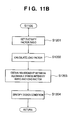
- step S1106 earthquake-proof reinforcement design is executed for the members selected in step S1105. Which load factor and allowable stress intensity ratio are to be used for design by earthquake-proof reinforcement is determined from the relationship between the allowable stress intensity ratio and the load factor. Detailed processing is executed according to the flow chart shown in Fig. 11B. The detailed processing step of the earthquake-proof reinforcement design will be described with reference to the flow chart shown in Fig. 11B.
- step S1201 of Fig. 11B the ductility factor ratio for the pipe rack formed from the selected members is set.
- the ductility factor ratio is one of important parameters used to calculate the safety factor for determining the margin for a design load, i.e., the load factor and determine the ultimate load in the plastic region.
- the relationship between the structural modulus and the ductility factor ratio will be described below.
- the restoring force characteristic in a frame structure depends on the structure of members, the joint method for the member, and the load (P) and displacement.
- Equation (9) can be basically regarded as an acceleration response spectrum.
- the ductility factor ratio of a pipe rack is obtained as about 3.0 by an earthquake-proof test, this value may be employed as a deformation magnification in the calculation.
- an arbitrary constant may be set as the ductility factor ratio.
- the earthquake-proof reinforcement method using a damper member for the column member foundation gives a structural characteristic for widening the elastic region and plastic deformation range, and earthquake-proof performance. Hence, the region of material selection and design load can be widened as compared to the prior art.
- step S1202 of Fig. 11B on the basis of the ductility factor ratio set in step S1201, a load factor for plastic design considering the ultimate load of the pipe rack is calculated on the basis of equation (11).
- a structural modulus is a numerical value determined by the shape of a structure in calculating the possession strength of the structure.
- a possession strength is designed to prevent any collapse of a structure even when the members of the structure exceed the yield point stress, as in a design considering the ultimate strength.
- the value Ce has a meaning as a safety factor for the design load.
- a load obtained by multiplying the design load by the safety factor is the ultimate load.
- step S1203 processing of obtaining the relationship between the load factor (seismic intensity) and the allowable stress intensity ratio ( ⁇ /f) is executed.
- This relationship is obtained on the assumption of modeling in which the relationship between the load and the plastic deformation when plastic deformation occurs in the rack structure is approximated as a so-called completely elasto-plastic model, and the energy until collapse (work which is performed by the load and displacement) almost equals the restoring force (energy) when the behavior of the rack is replaced as an elastic member.
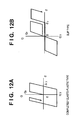
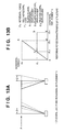
- Fig. 13A when a horizontal load acts on a structure (Fig. 13A), the relationship between the horizontal force X and the horizontal displacement ⁇ at that position can be simplified as shown in Fig. 13B in which the area of an elastic restoring force ⁇ OAB equals that of an elasto-plastic restoring force ⁇ OCDE.
- the elasto-plastic restoring force characteristic obtained by the earthquake-proof test corresponds to the OCD curve shown in Fig. 13B.
- the plastic design is to examine whether a structure is safe against the ultimate load, and the ultimate load is obtained by multiplying an acting load by the load factor. That is, design is executed such that an ultimate load is set by multiplying the design load (acting load) used for allowable stress intensity ratio design by the load factor (safety factor), and the magnitude of the load equals the load (collapse load) of collapse by the main frame structure.
- step S1203 the relationship between the allowable stress intensity ratio and the load factor is obtained for each of the selected members, as shown in Fig. 14.
- An increase in load which corresponds to a multiple of the load factor for the design load (acting load) is caused because a yield horizontal load Py which makes the displacement (strain) progress in the plastic region is replaced with a load which makes the elastic deformation progress as a load that increases from a point C (P y , ⁇ y ) to a point A (P E , ⁇ E ) in Fig. 13B.
- a yield horizontal load Py which makes the displacement (strain) progress in the plastic region
- a load which makes the elastic deformation progress as a load that increases from a point C (P y , ⁇ y ) to a point A (P E , ⁇ E ) in Fig. 13B.
- the design enable range also exceeds the elastic range (yield point), and the increase in load in the plastic range and the allowable stress intensity ratio corresponding to the increase in load.
- the architectural standard of Japan stipulates that the allowable stress intensity ratio may not exceed 1.0, as already described above.
- the design enable region widens. If a load factor corresponding to the maximum value (upper limit value) 1.0 of the allowable stress intensity ratio for a selected member is known, the load factor can be specified as the ultimate load at which the member breaks. Limit design that utilizes the design enable region at maximum becomes possible.
- step 51204 on the basis of the relationship between the load factor and the allowable stress intensity ratio obtained in step S1203 (Fig. 14), the design load is determined, and whether each selected member is appropriate is determined.
- the column member shown in Fig. 14 will be examined.
- the allowable stress intensity ratio ( ⁇ /f) of the column member is 0.88. That is, even when an increase in load is estimated as 50%, the allowable stress intensity ratio of the column member is smaller than 1.0 (upper limit value) and has a margin. If the value of 0.88 falls within the range of the allowable stress intensity ratio given as the degree of freedom of design, this column member satisfies the design condition.
- the processing returns to steps S1103 and 1104 to select members and re-set conditions such as the load condition (S1103 and S1104).
- step S1107 of Fig. 11A variation information of each member, such as a tilt or curve of each earthquake-proof reinforcement member, is measured, and the result is processed.
- step S1108 drawings of the pipe rack are created.
- step S1109 planning processing for the work of the earthquake-proof reinforcement is executed.
- step S1110 the design stress that is generated in the foundation is checked in accordance with foundation design calculation (step S1195).
- step S1111 a foundation in which a predetermined stress is generated is selected as an earthquake-proof reinforcement target.
- step S1112 the earthquake-proof reinforcement for the foundation portion selected in step S1111 is designed.
- the size of a reinforcing member for the method described with reference to Figs. 4 and 5 is determined.
- a member having any structure or any shape can be used as long as it can greatly reduce the bending moment transmitted from the column base to the foundation by forming a gap between the concrete portion with pedestal foundation and the column base instead of directly connecting them, filling the gap with a filler to reduce the interface bonding force between the concrete portion with pedestal foundation and the lower-side side surface of the column base, and allowing a bending deformation of the steel column base due to the action of an external force while absorbing most part of a bending moment in the steel column base by the filler and the concrete portion with pedestal foundation.
- the material of the filler is not limited to vibration isolating rubber, and any other material which elastically or plastically deforms can be used, such as various rubber materials, polymeric materials such as epoxy resin, metal materials such as an aluminum plate, aluminum alloy, and zinc plate, metal alloy materials, or materials such as asphalt containing petroleum or coal. That is, a material which can absorb the bending moment of the steel column base when an external force acts can be used.
- the gap may be left as a space instead of filling it with a filler.
- the effect for absorbing the bending moment of the steel column base when an external force acts in the space portion of the gap decreases.
- the allowable range of the bending deformation of the steel column base which is generated in accordance with action of an external force, can be widened using the space portion of the gap.
- the bending moment generated in the steel column base and transmitted from the column base to the foundation is reduced by the space portion of the gap.
- step S1113 drawing generation processing for the reinforcement design that is done in step S1112 is executed.
- the processing of the flow charts shown in Figs. 11A and 11B is executed by the CPU 1010 under the control of the OS 1002 in the information processing apparatus shown in Fig. 10.
- the member characteristic database looked up in checking the allowable stress intensity ratio of each member may be stored in the secondary storage device 1004c such as the hard disk in an information processing apparatus 1001 or a ROM 1004a.
- data may be transmitted/received to/from another information processing apparatus connected to the network (1005), and appropriately updated data may be used.
- the true strength of a pipe rack can be obtained in accordance with a quantitatively obtained ductility factor ratio, and the degree of an external force that can be covered can be clarified.
- optimum members can be selected.
- the object of the present invention can also be achieved by supplying a storage medium which stores software program codes for implementing the functions of the above-described embodiment to a system or apparatus and causing the computer (or a CPU or MPU) of the system or apparatus to read out and execute the program codes stored in the storage medium.
- the program codes read out from the storage medium implement the new function of the present invention by themselves, and the storage medium which stores the program codes constitutes the present invention.
- the storage medium for supplying the program codes for example, a floppy disk, hard disk, optical disk, magnetooptical disk, DVD, CD-ROM, magnetic tape, nonvolatile memory card, ROM, EEPROM, or the like can be used.
- the functions of the above-described embodiment are implemented not only when the readout program codes are executed by the computer but also when the operating system (OS) running on the computer performs part or all of actual processing on the basis of the instructions of the program codes.
- the functions of the above-described embodiment are also implemented when the program codes read out from the storage medium are written in the memory of a function expansion board inserted into the computer or a function expansion unit connected to the computer, and the CPU of the function expansion board or function expansion unit performs part or all of actual processing on the basis of the instructions of the program codes.
- a damper portion is provided between the base and the concrete member with pedestal foundation. Since a bending moment generated in the base by an external force can be reduced by the damper portion such that it is hardly transmitted to the foundation, the bending moment that the foundation member takes a share can be reduced. Hence, as compared to a structure before earthquake-proof reinforcement, the ductility factor ratio can be improved, and the design enable region can be widened by broadening the elastic range and plastic deformation range of the member.
- the ultimate load of a pipe rack can be specified from the relationship between the load factor and the allowable stress intensity ratio.
Landscapes
- Engineering & Computer Science (AREA)
- Architecture (AREA)
- Theoretical Computer Science (AREA)
- Physics & Mathematics (AREA)
- Structural Engineering (AREA)
- Civil Engineering (AREA)
- Mechanical Engineering (AREA)
- General Physics & Mathematics (AREA)
- General Engineering & Computer Science (AREA)
- Chemical & Material Sciences (AREA)
- Chemical Kinetics & Catalysis (AREA)
- Electrochemistry (AREA)
- Geometry (AREA)
- Evolutionary Computation (AREA)
- Computer Hardware Design (AREA)
- Business, Economics & Management (AREA)
- Emergency Management (AREA)
- Environmental & Geological Engineering (AREA)
- Buildings Adapted To Withstand Abnormal External Influences (AREA)
- Working Measures On Existing Buildindgs (AREA)
- Rod-Shaped Construction Members (AREA)
- Supports For Pipes And Cables (AREA)
- Pipeline Systems (AREA)
- Management, Administration, Business Operations System, And Electronic Commerce (AREA)
Abstract
Description
ductility factor ratio= (ductility factor of earthquake-proof reinforcement structure)/(ductility factor of structure having no earthquake-proof reinforcement structure).
wherein the gap is filled with a filler, the allowable range of the bending deformation of the steel column base, which is generated in accordance with action of an external force, can be widened using the space portion of the gap. As a result, the bending moment generated in the steel column base and transmitted from the column base to the foundation is reduced by the space portion of the gap. With the above-described two effects, the same effect as in the case wherein the gap is filled with a filler can be expected even when the gap is left as a space.
Claims (14)
- A design analysis method of an earthquake-proof reinforcement structure, characterized by comprising:the selection step (S1103) of selecting a member of the earthquake-proof reinforcement structure with reference to an allowable stress intensity ratio of the member;the ductility factor ratio setting step (S1104, S1105, S1201) of setting a ductility factor ratio allowable as a deformation magnification by earthquake-proof reinforcement of the selected member;the load factor calculation step (S1202) of calculating an increase in load in a plasticity range, which acts on the selected member, on the basis of the set ductility factor ratio;the calculation step (S1203) of calculating an allowable stress intensity ratio corresponding to the increase in load in the plasticity range; andthe specifying step (S1204, S1106) of, when the calculated allowable stress intensity ratio is defined as a maximum value, specifying the corresponding increase in load in the plasticity range as an ultimate load at which the selected member collapses.
- The analysis according to claim 1, characterized in that the maximum value of the allowable stress intensity ratio is 1.0.
- The analysis according to claim 1, characterized in that the ductility factor ratio in earthquake-proof reinforcement having a damper portion arranged between a base of a column member and a reinforcing member using concrete with pedestal foundation in the earthquake-proof reinforcement structure is not less than 3.0.
- The analysis method according to claim 1, characterized in that in the selection step, a load of an object supported by the earthquake-proof reinforcement structure is used as a condition for member selection.
- The analysis method according to claim 1, characterized in that in the specifying step, for an earthquake-proof reinforcement structure formed from a plurality of types of members, ultimate loads specified for the respective members are compared, and a minimum ultimate load of the ultimate loads is specified as the ultimate load of the earthquake-proof reinforcement structure.
- The analysis method according to claim 1, characterized in that in the specifying step, for an earthquake-proof reinforcement structure formed from a main member and a reinforcing member for reinforcing the main member, ultimate loads specified for the respective members are compared, and when the ultimate load of the main member is larger than that of the reinforcing member, the ultimate load of the main member is specified as the ultimate load of the earthquake-proof reinforcement structure.
- The analysis method according to claim 6, characterized in that the main member comprises a beam or column member, and the reinforcing member comprises a brace member.
- A storage medium which stores a program module for causing a computer to execute a design analysis method of an earthquake-proof reinforcement structure, characterized by comprising:a selection module (S1103, 1002, 1010) for selecting a member of the earthquake-proof reinforcement structure with reference to an allowable stress intensity ratio of the member;a ductility factor ratio setting module (S1104, S1105, S1201, 1002, 1010) for setting a ductility factor ratio allowable as a deformation magnification by earthquake-proof reinforcement of the selected member;a load factor calculation module (S1202, 1002, 1010) for calculating an increase in load in a plasticity range, which acts on the selected member, on the basis of the set ductility factor ratio;a calculation module (S1203, 1002, 1010) for calculating an allowable stress intensity ratio corresponding to the increase in load in the plasticity range; anda specifying step (S1204, S1106, 1002, 1010) for, when the calculated allowable stress intensity ratio is defined as a maximum value, specifying the corresponding increase in load in the plasticity range as an ultimate load at which the selected member collapses.
- The medium according to claim 8, characterized in that the maximum value of the allowable stress intensity ratio is 1.0.
- The medium according to claim 8, characterized in that the ductility factor ratio in earthquake-proof reinforcement having a damper portion arranged between a base of a column member and a reinforcing member using concrete with pedestal foundation in the earthquake-proof reinforcement structure is not less than 3.0.
- The medium according to claim 8, characterized in that in the selection module, selection processing of the member is executed using a load of an object supported by the earthquake-proof reinforcement structure as a condition for member selection.
- The medium according to claim 8, characterized in that in the specifying module, for an earthquake-proof reinforcement structure formed from a plurality of types of members, ultimate loads specified for the respective members are compared, and a minimum ultimate load of the ultimate loads is specified as the ultimate load of the earthquake-proof reinforcement structure.
- The medium according to claim 8, characterized in that in the specifying module, for an earthquake-proof reinforcement structure formed from a main member and a reinforcing member for reinforcing the main member, ultimate loads specified for the respective members are compared, and when the ultimate load of the main member is larger than that of the reinforcing member, the ultimate load of the main member is specified as the ultimate load of the earthquake-proof reinforcement structure.
- A design analysis method of an earthquake-proof reinforcement structure, characterized by comprising the steps of:wherein the design analysis method of specifying the ultimate load comprises:designing selected members on the basis of an ultimate load specified by a design analysis method (S1101, S1190, S1195, S1107, S1108); anddesigning earthquake-proof reinforcement by providing a damper portion between a base of a column member of the designed selected members and a reinforcing member using concrete with pedestal foundation, which reinforces the base (S1110, S1111, S1112, S1113),the selection step (S1103) of selecting a member of the earthquake-proof reinforcement structure with reference to an allowable stress intensity ratio of the member;the ductility factor ratio setting step (S1104, S1105, S1201) of setting a ductility factor ratio allowable as a deformation magnification by earthquake-proof reinforcement of the selected member;the load factor calculation step (S1202) of calculating an increase in load in a plasticity range, which acts on the selected member, on the basis of the set ductility factor ratio;the calculation step (S1203) of calculating an allowable stress intensity ratio corresponding to the increase in load in the plasticity range; andthe specifying step (S1204, S1106) of, when the calculated allowable stress intensity ratio is defined as a maximum value, specifying the corresponding increase in load in the plasticity range as an ultimate load at which the selected member collapses.
Applications Claiming Priority (2)
| Application Number | Priority Date | Filing Date | Title |
|---|---|---|---|
| JP2000393357A JP3493178B2 (en) | 2000-12-25 | 2000-12-25 | Seismic reinforcement structure design method, storage medium |
| JP2000393357 | 2000-12-25 |
Publications (2)
| Publication Number | Publication Date |
|---|---|
| EP1219763A2 true EP1219763A2 (en) | 2002-07-03 |
| EP1219763A3 EP1219763A3 (en) | 2004-07-28 |
Family
ID=18859173
Family Applications (1)
| Application Number | Title | Priority Date | Filing Date |
|---|---|---|---|
| EP01128474A Withdrawn EP1219763A3 (en) | 2000-12-25 | 2001-12-06 | Design analysis method of earthquake-proof reinforcement structure, and storage medium |
Country Status (9)
| Country | Link |
|---|---|
| US (1) | US7040176B2 (en) |
| EP (1) | EP1219763A3 (en) |
| JP (1) | JP3493178B2 (en) |
| KR (1) | KR100520318B1 (en) |
| CN (1) | CN1198997C (en) |
| CA (1) | CA2365035A1 (en) |
| MX (1) | MXPA01013030A (en) |
| PE (1) | PE20020645A1 (en) |
| TW (1) | TW564280B (en) |
Cited By (1)
| Publication number | Priority date | Publication date | Assignee | Title |
|---|---|---|---|---|
| CN104850532A (en) * | 2015-05-15 | 2015-08-19 | 中国电力科学研究院 | Computing method for extreme load of compression-bending member |
Families Citing this family (41)
| Publication number | Priority date | Publication date | Assignee | Title |
|---|---|---|---|---|
| JP4610098B2 (en) * | 2001-02-09 | 2011-01-12 | 旭化成建材株式会社 | Column base strength judgment system |
| US7260509B1 (en) * | 2001-07-06 | 2007-08-21 | Cingular Wireless Ii, Llc | Method for estimating changes in product life resulting from HALT using quadratic acceleration model |
| WO2005073688A1 (en) * | 2004-01-21 | 2005-08-11 | California Institute Of Technology | Extreme event performance evaluation of a structure using real-time hystersis monitoring |
| JP5179084B2 (en) * | 2007-03-30 | 2013-04-10 | 旭化成ホームズ株式会社 | Building structural margin setting support system |
| JP2009145995A (en) * | 2007-12-11 | 2009-07-02 | Toshiba It Service Kk | Base-isolating device installation floor evaluation system |
| CN102033023B (en) * | 2010-10-09 | 2013-04-24 | 北京交通大学 | Method for seismic design of multi-ribbed composite wall |
| JP5827778B2 (en) * | 2011-06-27 | 2015-12-02 | 学校法人慶應義塾 | Nonlinear structural load transfer analyzer |
| TWI477678B (en) * | 2011-10-17 | 2015-03-21 | Univ Nat Kaohsiung Applied Sci | Seismic building structure |
| JP5943614B2 (en) * | 2012-01-16 | 2016-07-05 | 株式会社Lixil | Calculation method of allowable shear strength of bearing wall with opening, design method of bearing wall with opening, calculation device of allowable shear strength of bearing wall with opening, calculation program of allowable shear strength of bearing wall with opening |
| US9835744B2 (en) * | 2012-10-16 | 2017-12-05 | Colorado School Of Mines | Virtual electrode current injection using seismic focusing and seismoelectric conversion |
| CN103116709A (en) * | 2013-03-08 | 2013-05-22 | 山东理工大学 | Computing method for circumferential stress of absorber annular valve sheet |
| CN103106349A (en) * | 2013-03-08 | 2013-05-15 | 山东理工大学 | Method for calculating radial stress of annular valve plate of vibration absorber |
| CN103294919B (en) * | 2013-05-31 | 2016-03-02 | 山东理工大学 | Vibration damper circular sandwich valve plate determines the method for radial stress under non-uniform distributed pressure |
| US9255408B2 (en) | 2014-03-17 | 2016-02-09 | Hitachi Metals Techno, Ltd. | Column structure and base member |
| US9422717B2 (en) | 2014-03-17 | 2016-08-23 | Senqcia Corporation | Column structure and base member |
| WO2015140890A1 (en) * | 2014-03-17 | 2015-09-24 | 日立機材株式会社 | Column structure and base member |
| CN104213635B (en) * | 2014-08-27 | 2015-12-09 | 广东省建筑设计研究院 | Design method for preventing continuous collapse under failure of prestressed cable in string structure of building system |
| JP6542012B2 (en) * | 2015-04-08 | 2019-07-10 | 東京電力ホールディングス株式会社 | Simplified earthquake resistance evaluation method of substation outdoor steel frame |
| CN105160055B (en) * | 2015-07-07 | 2018-01-16 | 重庆大学 | A kind of Seismic Design Method of the frame structure based on displacement |
| JP6567368B2 (en) * | 2015-09-01 | 2019-08-28 | センクシア株式会社 | Reinforcement structure and reinforcement method for existing columns |
| CN105160136B (en) * | 2015-10-08 | 2017-12-29 | 山东理工大学 | The computational methods of hydro-pneumatic spring not uniform thickness annular valve block maximum radial stress |
| CN105138806B (en) * | 2015-10-08 | 2018-01-16 | 山东理工大学 | The strength check methods of hydro-pneumatic spring not uniform thickness annular valve block |
| CN105279319B (en) * | 2015-10-08 | 2018-01-05 | 山东理工大学 | The computational methods of hydro-pneumatic spring not uniform thickness annular valve block Maximum circumferential stress |
| CN105260533B (en) * | 2015-10-08 | 2018-01-05 | 山东理工大学 | The hydro-pneumatic spring computational methods that uniform thickness annular valve block does not deform |
| CN105893702B (en) * | 2016-04-27 | 2018-11-30 | 山东理工大学 | End contact lacks the calculation method of the reinforced each stress of major-minor spring in piece root |
| US10533338B2 (en) | 2017-05-11 | 2020-01-14 | Katerra, Inc. | Connector for use in inter-panel connection between shear wall elements |
| CN107401287A (en) * | 2017-07-19 | 2017-11-28 | 青岛理工大学 | Building reinforcing method based on stress transfer analysis |
| CN111159805B (en) * | 2019-12-26 | 2023-02-21 | 黄河水利委员会黄河水利科学研究院 | Seismic safety analysis method for sluice chamber structure |
| CN111622369A (en) * | 2020-06-10 | 2020-09-04 | 上海大学 | Optimal design method for anti-buckling restrained brace steel frame structure |
| JP7728094B2 (en) * | 2021-03-26 | 2025-08-22 | 三菱重工業株式会社 | Architectural design support device and architectural design support method |
| CN113340727B (en) * | 2021-05-24 | 2022-11-11 | 机械工业第九设计研究院股份有限公司 | Device and method for nondestructive testing of mechanical parameters of building concrete |
| CN113740172B (en) * | 2021-09-14 | 2024-04-30 | 中建八局第一建设有限公司 | A loading test device for steel structure composite columns |
| CN115168946A (en) * | 2022-06-28 | 2022-10-11 | 中国国家铁路集团有限公司 | High-strength cold-cast anchor structure size parametric analysis method |
| CN115324341B (en) * | 2022-08-22 | 2023-10-27 | 湖南嘉晟住建科技有限公司 | Construction method of steel-concrete composite beam |
| KR102505492B1 (en) * | 2022-10-06 | 2023-03-03 | 건국대학교 산학협력단 | Blast resistant design method of blast resistant structure using static displacement and blast resistant structure designed by the method |
| KR102524603B1 (en) * | 2022-11-02 | 2023-04-21 | 한국안전기술연합(주) | Method and apparatus for providing information necessary for the installation of temporary fence of construction site |
| CN116337383B (en) * | 2023-05-29 | 2023-07-21 | 安特利智能科技有限公司 | Anti-seismic performance detection device of anti-seismic support |
| CN116861710B (en) * | 2023-09-04 | 2023-11-10 | 长江勘测规划设计研究有限责任公司 | A method for calculating the internal force and checking the strength of the rack force transmission system of the ship lift |
| CN117822935A (en) * | 2024-01-16 | 2024-04-05 | 中建二局第三建筑工程有限公司 | A reconstruction structure and construction technology of adding frame beams to an existing beamless floor |
| CN119129087B (en) * | 2024-11-14 | 2025-02-14 | 安徽省交通规划设计研究总院股份有限公司 | Seismic design method of prestressed pipe pile frame for prefabricated assembled pile-slab highway bridge |
| CN119720633A (en) * | 2024-11-21 | 2025-03-28 | 中国人民解放军陆军工程大学 | Carbon fiber cloth prestressed tension shield segment reinforcement method |
Family Cites Families (9)
| Publication number | Priority date | Publication date | Assignee | Title |
|---|---|---|---|---|
| US4964060A (en) | 1985-12-04 | 1990-10-16 | Hartsog Charles H | Computer aided building plan review system and process |
| US5533307A (en) * | 1994-11-29 | 1996-07-09 | National Science Council | Seismic energy dissipation device |
| US6237303B1 (en) * | 1995-04-11 | 2001-05-29 | Seismic Structural Design | Steel frame stress reduction connection |
| JP3603130B2 (en) * | 1996-07-02 | 2004-12-22 | 株式会社竹中工務店 | Root-wound reinforcement structure for column bases such as steel columns |
| JPH10142112A (en) | 1996-11-08 | 1998-05-29 | Ohbayashi Corp | Method and system for evaluating earthquake resistance property of earthquake-resistance performance of existing building and method and system for evaluating remodeling priority of a group of existing buildings |
| JP3425365B2 (en) * | 1998-06-25 | 2003-07-14 | 株式会社 日立インダストリイズ | Apparatus and method for testing structure |
| JP3787799B2 (en) * | 1999-05-14 | 2006-06-21 | 清水建設株式会社 | Steel tower design and diagnosis system |
| TW445334B (en) * | 1999-06-01 | 2001-07-11 | Ohbayashi Corp | Elevated bridge infrastructure and design method for designing the same |
| JP3401466B2 (en) * | 1999-12-17 | 2003-04-28 | 日本海エル・エヌ・ジー株式会社 | Root-wrap type seismic retrofit structure for column base of column member and root-wrap type seismic retrofit method |
-
2000
- 2000-12-25 JP JP2000393357A patent/JP3493178B2/en not_active Expired - Fee Related
-
2001
- 2001-12-06 US US10/007,969 patent/US7040176B2/en not_active Expired - Fee Related
- 2001-12-06 EP EP01128474A patent/EP1219763A3/en not_active Withdrawn
- 2001-12-12 CA CA002365035A patent/CA2365035A1/en not_active Abandoned
- 2001-12-17 MX MXPA01013030A patent/MXPA01013030A/en unknown
- 2001-12-20 TW TW090131731A patent/TW564280B/en not_active IP Right Cessation
- 2001-12-21 PE PE2001001299A patent/PE20020645A1/en not_active Application Discontinuation
- 2001-12-24 KR KR10-2001-0084412A patent/KR100520318B1/en not_active Expired - Fee Related
- 2001-12-25 CN CNB01144018XA patent/CN1198997C/en not_active Expired - Fee Related
Cited By (2)
| Publication number | Priority date | Publication date | Assignee | Title |
|---|---|---|---|---|
| CN104850532A (en) * | 2015-05-15 | 2015-08-19 | 中国电力科学研究院 | Computing method for extreme load of compression-bending member |
| CN104850532B (en) * | 2015-05-15 | 2018-03-09 | 中国电力科学研究院 | The computational methods of the ultimate load of bending component |
Also Published As
| Publication number | Publication date |
|---|---|
| JP2002194894A (en) | 2002-07-10 |
| JP3493178B2 (en) | 2004-02-03 |
| EP1219763A3 (en) | 2004-07-28 |
| KR20020053009A (en) | 2002-07-04 |
| PE20020645A1 (en) | 2002-07-10 |
| MXPA01013030A (en) | 2004-05-21 |
| KR100520318B1 (en) | 2005-10-14 |
| TW564280B (en) | 2003-12-01 |
| CN1198997C (en) | 2005-04-27 |
| US7040176B2 (en) | 2006-05-09 |
| US20020095275A1 (en) | 2002-07-18 |
| CA2365035A1 (en) | 2002-06-25 |
| CN1361342A (en) | 2002-07-31 |
Similar Documents
| Publication | Publication Date | Title |
|---|---|---|
| US7040176B2 (en) | Design analysis method of earthquake-proof reinforcement structure, and storage medium | |
| Powell | Progressive collapse: Case studies using nonlinear analysis | |
| Priestley | Displacement-based seismic assessment of reinforced concrete buildings | |
| Kowalsky et al. | Displacement‐based design of RC bridge columns in seismic regions | |
| Leelataviwat et al. | Toward performance‐based seismic design of structures | |
| Foutch et al. | Modeling of steel moment frames for seismic loads | |
| Priestley et al. | Direct displacement-based seismic design of concrete buildings | |
| Mwafy et al. | Significance of severe distant and moderate close earthquakes on design and behavior of tall buildings | |
| Tremblay et al. | Comparison of seismic design provisions for buckling restrained braced frames in Canada, United States, Chile, and New Zealand | |
| Etli et al. | Assessment of seismic behavior factor of code-designed steel–concrete composite buildings | |
| Ganjavi et al. | Optimum performance-based design of concentrically braced steel frames subjected to near-fault ground motion excitations | |
| Kunnath | Performance-based seismic design and evaluation of building structures | |
| Hagen | Performance-based analysis of a reinforced concrete shear wall building | |
| Bresler | Behavior of Structural Elements | |
| Asgarian et al. | Evaluation of seismic performance of moment resisting frames considering vertical component of ground motion | |
| GHODRATI et al. | The effect of analysis methods on the response of steel dual-system frame buildings for seismic retrofitting | |
| Etli et al. | Comparative analysis of composite buildings produced in national and international standards | |
| Fu et al. | Influence factors and repair effects of seismic damage to a box section steel pier | |
| Kinali | Seismic fragility assessment of steel frames in the central and eastern United States | |
| Gholamrezatabar et al. | Modified seismic design lateral force distribution for the Performance-Based Plastic Design (PBPD) of steel moment structures considering soil flexibility | |
| Benavent-Climent | A seismic index method for vulnerability assessment of existing frames: application to RC structures with wide beams in Spain | |
| Félix-Soto et al. | Seismic performance and expected economic losses of dual MRF RC buildings with buckling-restrained braces using FEMA P-58 | |
| Ganjehei et al. | Inovativna metoda za krivulje inkrementalne dinamičke analize djelomično izoliranih mostova | |
| Ganjehei et al. | Innovative method for incremental dynamic analysis curves in semi-isolated bridges | |
| Abediasl et al. | TBSC 2018 Provisions on Design Shear Forces for Buildings with Rigid Basements |
Legal Events
| Date | Code | Title | Description |
|---|---|---|---|
| PUAI | Public reference made under article 153(3) epc to a published international application that has entered the european phase |
Free format text: ORIGINAL CODE: 0009012 |
|
| AK | Designated contracting states |
Kind code of ref document: A2 Designated state(s): AT BE CH CY DE DK ES FI FR GB GR IE IT LI LU MC NL PT SE TR |
|
| AX | Request for extension of the european patent |
Free format text: AL;LT;LV;MK;RO;SI |
|
| PUAL | Search report despatched |
Free format text: ORIGINAL CODE: 0009013 |
|
| AK | Designated contracting states |
Kind code of ref document: A3 Designated state(s): AT BE CH CY DE DK ES FI FR GB GR IE IT LI LU MC NL PT SE TR |
|
| AX | Request for extension of the european patent |
Extension state: AL LT LV MK RO SI |
|
| 17P | Request for examination filed |
Effective date: 20041210 |
|
| AKX | Designation fees paid |
Designated state(s): ES GR IT TR |
|
| REG | Reference to a national code |
Ref country code: DE Ref legal event code: 8566 |
|
| STAA | Information on the status of an ep patent application or granted ep patent |
Free format text: STATUS: THE APPLICATION IS DEEMED TO BE WITHDRAWN |
|
| 18D | Application deemed to be withdrawn |
Effective date: 20060701 |