EP1219160A1 - Mähdrescher mit einer Kanaleinrichtung zur pneumatischen Reinigung einer Axialtrenneinrichtung - Google Patents
Mähdrescher mit einer Kanaleinrichtung zur pneumatischen Reinigung einer Axialtrenneinrichtung Download PDFInfo
- Publication number
- EP1219160A1 EP1219160A1 EP01129684A EP01129684A EP1219160A1 EP 1219160 A1 EP1219160 A1 EP 1219160A1 EP 01129684 A EP01129684 A EP 01129684A EP 01129684 A EP01129684 A EP 01129684A EP 1219160 A1 EP1219160 A1 EP 1219160A1
- Authority
- EP
- European Patent Office
- Prior art keywords
- air
- fan
- combine
- outlet
- line
- Prior art date
- Legal status (The legal status is an assumption and is not a legal conclusion. Google has not performed a legal analysis and makes no representation as to the accuracy of the status listed.)
- Granted
Links
- 238000004140 cleaning Methods 0.000 title description 3
- 239000000356 contaminant Substances 0.000 claims description 7
- 239000012535 impurity Substances 0.000 abstract description 2
- 238000001816 cooling Methods 0.000 description 22
- 238000000926 separation method Methods 0.000 description 9
- 239000010902 straw Substances 0.000 description 9
- 239000000428 dust Substances 0.000 description 4
- 238000011109 contamination Methods 0.000 description 3
- 238000012423 maintenance Methods 0.000 description 3
- 241001272996 Polyphylla fullo Species 0.000 description 2
- 238000002485 combustion reaction Methods 0.000 description 2
- 238000002360 preparation method Methods 0.000 description 2
- 241001124569 Lycaenidae Species 0.000 description 1
- 239000004698 Polyethylene Substances 0.000 description 1
- 230000006735 deficit Effects 0.000 description 1
- 230000003292 diminished effect Effects 0.000 description 1
- 210000005069 ears Anatomy 0.000 description 1
- 239000000446 fuel Substances 0.000 description 1
- 238000003306 harvesting Methods 0.000 description 1
- 238000002347 injection Methods 0.000 description 1
- 239000007924 injection Substances 0.000 description 1
- 239000000463 material Substances 0.000 description 1
- 239000010705 motor oil Substances 0.000 description 1
- 239000003921 oil Substances 0.000 description 1
- -1 polyethylene Polymers 0.000 description 1
- 229920000573 polyethylene Polymers 0.000 description 1
- 238000012216 screening Methods 0.000 description 1
- 239000000243 solution Substances 0.000 description 1
- 238000010408 sweeping Methods 0.000 description 1
Images


Classifications
-
- A—HUMAN NECESSITIES
- A01—AGRICULTURE; FORESTRY; ANIMAL HUSBANDRY; HUNTING; TRAPPING; FISHING
- A01F—PROCESSING OF HARVESTED PRODUCE; HAY OR STRAW PRESSES; DEVICES FOR STORING AGRICULTURAL OR HORTICULTURAL PRODUCE
- A01F12/00—Parts or details of threshing apparatus
- A01F12/54—Arrangements for collecting or removing dust
-
- A—HUMAN NECESSITIES
- A01—AGRICULTURE; FORESTRY; ANIMAL HUSBANDRY; HUNTING; TRAPPING; FISHING
- A01F—PROCESSING OF HARVESTED PRODUCE; HAY OR STRAW PRESSES; DEVICES FOR STORING AGRICULTURAL OR HORTICULTURAL PRODUCE
- A01F12/00—Parts or details of threshing apparatus
- A01F12/18—Threshing devices
- A01F12/184—Cleaning means
-
- A—HUMAN NECESSITIES
- A01—AGRICULTURE; FORESTRY; ANIMAL HUSBANDRY; HUNTING; TRAPPING; FISHING
- A01F—PROCESSING OF HARVESTED PRODUCE; HAY OR STRAW PRESSES; DEVICES FOR STORING AGRICULTURAL OR HORTICULTURAL PRODUCE
- A01F7/00—Threshing apparatus
- A01F7/02—Threshing apparatus with rotating tools
- A01F7/06—Threshing apparatus with rotating tools with axles in line with the feeding direction ; Axial threshing machines
- A01F7/065—Threshing apparatus with rotating tools with axles in line with the feeding direction ; Axial threshing machines with cage sweep mechanisms
Definitions
- the invention relates to a combine harvester with an axial separating device for crop, a fan and a duct device, the airflow generated by the fan for Top of the axial separator directs to contaminants to blow away from it, the channel device being a line which includes an inlet that is substantially horizontal moving air from the fan, and an outlet the air flows out essentially vertically downwards, having.
- a hybrid machine with a transverse threshing drum and a pair of axial separation units is disclosed in US 4,739,773 A the disclosure of which is incorporated herein by reference is recorded.
- the axial separation units include cylindrical tubes in which rotors are accommodated. It was found out that dust, chaff and others Impurities on the tops of the axial Collect separators.
- the present invention relates to the use of Cooling air for the engine to pneumatically dust, chaff and others Contamination from the top of an axial separator and to blow the drive devices of their rotor.
- a Duct device directs cooling air from the engine cooling system to Top of the axial separation device and the rotor drive devices.
- the channel device comprises an arch curved pipe, one near the - to the loading the motor with a cooling air fan Has inlet to one of the fan essentially horizontally moving air flow.
- the administration extends in an arc to gradually flow in the air Essentially vertically down on the top of the Redirect axial separator.
- the line has one narrowed section on which is a relatively small Cross-sectional area in which the air flow moves. This narrowed section serves as a restriction that limits the airflow essentially prevents this point from swirling upward.
- the outlet of the line can vary from the narrowed section expand outside to have a larger cross-sectional area define in which the air flow can move, thereby the flow through the line is further improved.
- a deflector can direct the airflow into an outlet downstream divide forward and part towards the rear.
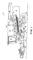
- FIG. 1 illustrates a harvester in the form of a self-propelled combine 10 with a supporting structure 12.
- the supporting structure 12 is provided by wheels 14, in Intervention with ground-based devices supported and promoted.
- the wheels 14 engaged with the ground are driven by propulsion means that a motor 48 to Advance the combine 10 over a field.
- the front part of the combine 10 is with a cutter 16 equipped to harvest good standing in a field and that to convey harvested crops upwards by means of an inclined conveyor 18 and feed the threshing and separating mechanism.
- the threshing and Separation mechanism includes a transverse threshing drum 20 and an associated concave 21 to which the harvested crop is fed first.
- the threshed good then becomes one Wiping roller 23 and a guide drum 22 supplied, from which it enters the axial separation device 24.
- a similar axial separator 24 is in US 4,884,994 which is incorporated by reference here.
- a Such axial separating device comprises a pair of tubes arranged side by side. Each tube is equipped with a rotor that has fixed fingers or tines. Threshed material from the guide drum 22 is passed from above into the tubes, where it comes into engagement of the rotors. The upper inside of each tube is equipped with runners to convey the crop backwards, with the rotor tines throwing the crop up to engage the runners. The bottom of each of the tubes is rusted through the grain and chaff fall onto the preparation floor 32. Straw residues are ejected at the back of the tubes.
- Grain and chaff from the threshing and separating devices fall out, fall on a screw conveyor 30 and Preparation floor 32, which the grain and the chaff to the sieve box 34 promote.
- the screen box 34 is with a blower assembly 36 equipped to separate the grain from the chaff support.
- Clean grain is arranged by a cross Screw conveyor 38 fed to an elevator (not shown), which conveys the grain into a grain tank 40.
- a transversely arranged Sweeping auger conveyor 42 directs non-threshed ears via another elevator (not shown) back to Threshing. Clean grain is over from the grain tank 40 unload an unloading system, the transversely arranged Screw conveyor 44 and an unloading screw conveyor 46 includes.
- All different systems are powered by an internal combustion engine 48 powered by internal combustion by the operator is controlled from the operator's cab 50.
- the threshing devices, Separators and cleaning devices are within the side walls of the supporting structure 12 arranged.
- the motor 48 is on one Working platform 52 arranged on the back of the Grain tanks 40 is located.
- the work platform 52 is used to service the engine 48.
- the cooling system of the engine 48 includes a cooling fan, a radiator, an intercooler, Oil cooler, fuel cooler, condensers and one at 54 arranged, self-cleaning rotating sieve. Such a thing Cooling system is disclosed in US 4,906,262, which by Reference is included here.
- a channel device 56 for receiving part of the Cooling air flow is downstream of the motor 48 and pneumatically downstream the cooling fan of the motor 48.
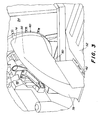
- the Channel device 56 is best shown in Figures 3, 4 and 5 illustrated. If cooling air from the cooling fan through the Heat exchanger and the rotating screen is drawn, it forms a transverse air flow. Most of this horizontal air flow is the motor 48 through a baffle 59th supplied, but an inlet 60 of the channel device 56 catches part of this airflow.
- the structure of the Channel device 56 changes the direction of the air flow so that he vertically down towards the axial separator 24 flows.
- the air is drawn from the duct device 56 through the outlet 62 ejected with one in the work platform 54 arranged opening is aligned. If the vertical now downward airflow directed through outlet 62 is, he encounters the deflector 66.
- the deflector 66 divides the Airflow in two components, one facing forward Component and a rearward component.
- the Deflector 66 changes the direction of airflow from one vertically downward airflow into an Essentially horizontal airflow that goes forward and backward has rear-facing components that serve Contamination from the top of the axial separators 24 to blow.
- Front for ejection serving openings 68 can be in the side walls of the load-bearing Structure 12 may be shaped. These discharge openings 68 can front space between the deflector 66 and the openings 68 Vent. Dust and chaff can escape through these openings 68 the combine 10 are ejected.
- a discharge gap 70 can between the underside of work platform 54 and the rear upper portion of the axial separators 24 may be shaped.
- This discharge gap 70 can be used to cover the rear Space between the deflector 66 and the rear portion of the To vent axial separation devices 24.
- the tip 72 of the deflector 66 is positioned such that a part of the air emerging from the duct device 56 forwards and a part of it forces backwards.
- the deflector 66 is sized and positioned to be a large one Air quantity forces forward because the discharge openings 68 are pneumatically inefficient than the discharge gap 70 because the Airflow must make a 90 degree turn to pass through the To be able to escape side walls. There is less air Back required because of the transversely oriented discharge gap 70 better with the airflow over the top of the Axial separating device 24 is aligned.
- the channel device 56 comprises an injection molded line 74 Made of polyethylene, which is between their inlet 60 and outlet 62 extends in an arc.
- the curvature of the bent pipe 74 gradually directs the air flow therein from a horizontal one Flow direction in a vertical flow direction. This Gradual redirection of air helps reduce speed to minimize that could occur if the airflow is redirected.
- Line 74 includes a constricted one Section 76 near the location where the airflow starts moving vertically. Much of the Airflow within line 74 is nearby the curved wall 78 of the line 74 at point A.
- the line 74 is dimensioned so that it is a relative forms a small structure near the cooling fan.
- a smaller one Line 74 reduces the blockage of air in the cooling system. The allows the air to flow more freely through the cooling system, which improves the efficiency of the cooling system. Moreover becomes a relatively small structure near the motor 48 an operator during maintenance work, such as engine oil level checks, hinder less. Because line 74 is such is created that they have an improved airflow through the Line 74 enables, it can be dimensioned relatively small, resulting in less obstruction of the air flow by the Cooling system and the cooling fan and a lower Impairment in the maintenance of the engine arises.
- the Line 74 is also positioned relatively close to the fan, so that less air is blown back from inlet 60 what otherwise the air flow through the cooling system and the Fan could hinder. Positioning line 74 in the proximity of the fan also allows line 74 to itself to receive faster moving air from the fan, what about this serves the speed of the air flow through line 74 to enlarge, making contaminants more effective from the Tops of the axial separators 24 are blown away, so that a smaller line 74 can be used.
- Inlet 60 is in the outer radial edge area of the fan positioned to provide an air flow with relative from the fan to get high speed.
Landscapes
- Life Sciences & Earth Sciences (AREA)
- Environmental Sciences (AREA)
- Threshing Machine Elements (AREA)
- Combines (AREA)
- Feeding And Watering For Cattle Raising And Animal Husbandry (AREA)
- Blow-Moulding Or Thermoforming Of Plastics Or The Like (AREA)
- Separating Particles In Gases By Inertia (AREA)
- Structures Of Non-Positive Displacement Pumps (AREA)
Abstract
Description
- Fig. 1
- eine halbschematische Seitenansicht eines Mähdreschers mit einer quer angeordneten Dreschtrommel und einer Axialtrenneinheit,
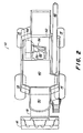
- Fig. 2
- eine halbschematische Draufsicht auf den Mähdrescher,
- Fig. 3
- eine perspektivische Ansicht der Kanaleinrichtung im Mähdrescher,
- Fig. 4
- eine Ansicht der Kanaleinrichtung,
- Fig. 5
- eine Draufsicht auf die Kanaleinrichtung, und
- Fig. 6
- eine Ansicht der Kanaleinrichtung, in der in Phantomansicht ein am Auslass des Kanals angeordneter Deflektor gezeigt wird.
Claims (4)
- Mähdrescher (10) mit einer Axialtrenneinrichtung (24) für Erntegut, einem Ventilator und einer Kanaleinrichtung (56), die einen vom Ventilator erzeugten Luftstrom zur Oberseite der Axialtrenneinrichtung (24) leitet, um Verunreinigungen von ihr fortzublasen, wobei die Kanaleinrichtung (56) eine Leitung (74) umfasst, die einen Einlass (60), der sich im Wesentlichen horizontal bewegende Luft vom Ventilator aufnimmt, und einen Auslass (62), aus dem Luft im Wesentlichen vertikal nach unten ausströmt, aufweist, dadurch gekennzeichnet, dass die Leitung (74) oberhalb des Auslasses (62) und in dessen Nähe einen verengten Abschnitt (76) aufweist, der eine Einschränkung des Luftstroms in der Leitung (74) bildet, um zu verhindern, dass Luft in der Nähe des verengten Abschnitts (76) nach oben wirbelt.
- Mähdrescher (10) nach Anspruch 1, dadurch gekennzeichnet, dass sich der Auslass (62) vom verengten Abschnitt (76) nach außen erweitert und eine größere Querschnittsfläche als der verengte Abschnitt (76) der Leitung (74) bildet.
- Mähdrescher (10) nach Anspruch 1 oder 2, dadurch gekennzeichnet, dass sich die Leitung (74) zwischen dem Einlass (60) und dem Auslass (62) in einem Bogen erstreckt.
- Mähdrescher (10) nach einem der Ansprüche 1 bis 3, dadurch gekennzeichnet, dass unterhalb des Auslasses ein Deflektor (66) angeordnet ist, der den Luftstrom teilweise nach vorn und teilweise nach hinten umlenkt.
Applications Claiming Priority (2)
| Application Number | Priority Date | Filing Date | Title |
|---|---|---|---|
| US746463 | 2000-12-21 | ||
| US09/746,463 US6468153B2 (en) | 2000-12-21 | 2000-12-21 | Air blast duct for cleaning axial separator |
Publications (2)
| Publication Number | Publication Date |
|---|---|
| EP1219160A1 true EP1219160A1 (de) | 2002-07-03 |
| EP1219160B1 EP1219160B1 (de) | 2005-03-23 |
Family
ID=25000952
Family Applications (1)
| Application Number | Title | Priority Date | Filing Date |
|---|---|---|---|
| EP01129684A Expired - Lifetime EP1219160B1 (de) | 2000-12-21 | 2001-12-13 | Mähdrescher mit einer Kanaleinrichtung zur pneumatischen Reinigung einer Axialtrenneinrichtung |
Country Status (9)
| Country | Link |
|---|---|
| US (1) | US6468153B2 (de) |
| EP (1) | EP1219160B1 (de) |
| AR (1) | AR032203A1 (de) |
| AT (1) | ATE291348T1 (de) |
| AU (1) | AU783182B2 (de) |
| BR (1) | BR0106360A (de) |
| CA (1) | CA2355024C (de) |
| DE (1) | DE50105683D1 (de) |
| DK (1) | DK1219160T3 (de) |
Families Citing this family (12)
| Publication number | Priority date | Publication date | Assignee | Title |
|---|---|---|---|---|
| US6796897B1 (en) * | 2003-09-17 | 2004-09-28 | Deere & Company | Airfoil for an axial separator cleaning air blast duct |
| US8695722B2 (en) * | 2003-10-09 | 2014-04-15 | Komatsu Ltd. | Bulldozer with improved visibility |
| WO2010110973A1 (en) * | 2009-03-26 | 2010-09-30 | Crown Equipment Corporation | Working vehicle having cooling system with suction device |
| AT510659B1 (de) * | 2010-10-22 | 2012-08-15 | Schrattenecker Franz Ing | Maisspindelwerfer |
| JP5096626B1 (ja) * | 2012-02-23 | 2012-12-12 | 株式会社小松製作所 | 作業車両 |
| DE102012112156A1 (de) * | 2012-12-12 | 2014-06-12 | Claas Selbstfahrende Erntemaschinen Gmbh | Selbstfahrender Feldhäcksler |
| BE1021101B1 (nl) * | 2013-07-12 | 2015-11-16 | Cnh Industrial Belgium Nv | Reinigingsgeheel voor een oogstmachine |
| GB201319215D0 (en) * | 2013-10-31 | 2013-12-18 | Agco As | Grain seperating apparatus in a combine harvester |
| US10028424B2 (en) * | 2014-04-25 | 2018-07-24 | Cnh Industrial America Llc | System for mounting an agricultural soil analyzer to agricultural implement |
| CN104206127A (zh) * | 2014-09-16 | 2014-12-17 | 河南科技大学 | 一种低破损滚齿式玉米脱粒机 |
| CN104855055A (zh) * | 2015-05-23 | 2015-08-26 | 刘子瑜 | 一种玉米脱粒机的滚筒结构 |
| US12096721B2 (en) * | 2018-09-07 | 2024-09-24 | Roy BREWIN | Crop dust separation system |
Citations (3)
| Publication number | Priority date | Publication date | Assignee | Title |
|---|---|---|---|---|
| US4284086A (en) * | 1980-09-22 | 1981-08-18 | Williams Dennis W | Threshing and separating apparatus |
| US4957467A (en) * | 1988-10-14 | 1990-09-18 | Alain Zachary | Device for primary separation of grain in a combine harvester for cereals |
| US5088960A (en) * | 1991-03-15 | 1992-02-18 | Deere & Company | Air blast for cleaning axial separator |
Family Cites Families (10)
| Publication number | Priority date | Publication date | Assignee | Title |
|---|---|---|---|---|
| US1848252A (en) * | 1924-11-24 | 1932-03-08 | Hermann Franz Josef | Dust removing device for threshing machines |
| US3370794A (en) * | 1965-11-08 | 1968-02-27 | Navy Usa | Annular plenum nozzle for controlling trajectory of rockets |
| CH462214A (de) * | 1967-05-05 | 1968-09-15 | Von Roll Ag | Wärmeaustauschkörper und Verfahren zu seiner Herstellung |
| US4279095A (en) * | 1980-01-02 | 1981-07-21 | Aasen Helen C | Flea vacuum system |
| US4589425A (en) * | 1984-07-02 | 1986-05-20 | Mitchell Jr Thomas A | Control apparatus for a combine |
| US4884994A (en) | 1984-08-29 | 1989-12-05 | Deere & Company | Axial flow rotary separator |
| US4739773A (en) | 1986-05-09 | 1988-04-26 | Deere & Company | Feeding arrangement for an axial flow rotary separator |
| US4906262A (en) | 1987-04-29 | 1990-03-06 | Deere & Company | Self cleaning rotary screen for the cooling air inlet of an engine enclosure |
| JP3752020B2 (ja) * | 1996-07-04 | 2006-03-08 | 清水建設株式会社 | 吹出口とダクトとの接続構造および保持具ならびに吹出口 |
| US5832708A (en) * | 1996-09-04 | 1998-11-10 | Scag Power Equipment, Inc. | Lawn mower |
-
2000
- 2000-12-21 US US09/746,463 patent/US6468153B2/en not_active Expired - Lifetime
-
2001
- 2001-08-14 CA CA002355024A patent/CA2355024C/en not_active Expired - Fee Related
- 2001-12-13 DE DE50105683T patent/DE50105683D1/de not_active Expired - Fee Related
- 2001-12-13 AT AT01129684T patent/ATE291348T1/de not_active IP Right Cessation
- 2001-12-13 DK DK01129684T patent/DK1219160T3/da active
- 2001-12-13 EP EP01129684A patent/EP1219160B1/de not_active Expired - Lifetime
- 2001-12-19 AU AU97299/01A patent/AU783182B2/en not_active Ceased
- 2001-12-20 BR BR0106360-0A patent/BR0106360A/pt not_active Application Discontinuation
- 2001-12-20 AR ARP010105934A patent/AR032203A1/es active IP Right Grant
Patent Citations (3)
| Publication number | Priority date | Publication date | Assignee | Title |
|---|---|---|---|---|
| US4284086A (en) * | 1980-09-22 | 1981-08-18 | Williams Dennis W | Threshing and separating apparatus |
| US4957467A (en) * | 1988-10-14 | 1990-09-18 | Alain Zachary | Device for primary separation of grain in a combine harvester for cereals |
| US5088960A (en) * | 1991-03-15 | 1992-02-18 | Deere & Company | Air blast for cleaning axial separator |
Also Published As
| Publication number | Publication date |
|---|---|
| EP1219160B1 (de) | 2005-03-23 |
| AU9729901A (en) | 2002-06-27 |
| US6468153B2 (en) | 2002-10-22 |
| ATE291348T1 (de) | 2005-04-15 |
| CA2355024C (en) | 2004-10-19 |
| US20020082062A1 (en) | 2002-06-27 |
| BR0106360A (pt) | 2002-08-20 |
| CA2355024A1 (en) | 2002-06-21 |
| AU783182B2 (en) | 2005-09-29 |
| AR032203A1 (es) | 2003-10-29 |
| DE50105683D1 (de) | 2005-04-28 |
| DK1219160T3 (da) | 2005-06-27 |
Similar Documents
| Publication | Publication Date | Title |
|---|---|---|
| EP2175710B1 (de) | Mähdrescher mit einem zusätzlichen trommelförderer zur strohabförderung und einer einzigen klappe zum wechseln zwischen schwadablage- und häckselbetrieb | |
| EP1731022B1 (de) | Reinigungseinrichtung für einen Mähdrescher | |
| US9295197B1 (en) | Combine harvester with blower equipped elevator | |
| DE3042731C2 (de) | ||
| US11771007B2 (en) | Sieve assembly for a crop processing system of an agricultural harvester | |
| EP1389416A2 (de) | Reinigungseinrichtung und Reinigungsgebläse für einen Mähdrescher | |
| EP1219160B1 (de) | Mähdrescher mit einer Kanaleinrichtung zur pneumatischen Reinigung einer Axialtrenneinrichtung | |
| DE2628707A1 (de) | Dreschmaschine, insbesondere maehdrescher | |
| EP3646707B1 (de) | Verbessertes reinigungssystem für einen mähdrescher | |
| EP2250869A1 (de) | Erntegutrestehäcksel und -verteilanordnung für einen Mähdrescher | |
| EP2368417B1 (de) | Erntemaschine mit einer Siebeinrichtung für Kühlluft | |
| EP0197292A1 (de) | Abwärts und rückwärts gerichteter Luftstrom für eine Erntemaschine mit vertikal versetzten Förderwalzen | |
| US9603307B2 (en) | Leaf screen cleaner | |
| DE102005027726A1 (de) | Radialgebläse für eine Reinigungseinrichtung für einen Mähdrescher | |
| EP1516524A1 (de) | Mähdrescher mit einer Kanaleinrichtung zur pneumatischen Reinigung einer Axialtrenneinrichtung | |
| EP2848113B1 (de) | Reinigungseinrichtung für einen Mähdrescher | |
| AU643119B2 (en) | Air blast for cleaning axial separator | |
| EP1354508B1 (de) | Axialabscheider mit Leitschiene | |
| EP1842415B1 (de) | Leitblech für eine Verteilvorrichtung eines Strohhäckslers | |
| DE1632879A1 (de) | Dreschvorrichtung | |
| DE102008040119A1 (de) | Mähdrescher mit einem zum Wechsel zwischen Schwadablagebetrieb und Häckselbetrieb in unterschiedlichen Drehrichtungen antreibbaren Trommelförderer | |
| DE102008040137A1 (de) | Mähdrescher mit einem zwischen einer Schwadablageposition und einer Häckselposition bewegbaren Endlosförderer | |
| EP0576737A1 (de) | Spreurückführeinrichtung für Mähdrescher | |
| EP2522210B1 (de) | Mähdrescher | |
| DE102008040116B4 (de) | Mähdrescher mit einem Endlosförderer und einem zwischen einer Schwadablageposition und einer Häckselposition bewegbaren Leitblech |
Legal Events
| Date | Code | Title | Description |
|---|---|---|---|
| PUAI | Public reference made under article 153(3) epc to a published international application that has entered the european phase |
Free format text: ORIGINAL CODE: 0009012 |
|
| AK | Designated contracting states |
Kind code of ref document: A1 Designated state(s): AT BE CH CY DE DK ES FI FR GB GR IE IT LI LU MC NL PT SE TR |
|
| AX | Request for extension of the european patent |
Free format text: AL;LT;LV;MK;RO;SI |
|
| 17P | Request for examination filed |
Effective date: 20030103 |
|
| AKX | Designation fees paid |
Designated state(s): AT BE CH CY DE DK ES FI FR GB GR IE IT LI LU MC NL PT SE TR |
|
| GRAP | Despatch of communication of intention to grant a patent |
Free format text: ORIGINAL CODE: EPIDOSNIGR1 |
|
| GRAS | Grant fee paid |
Free format text: ORIGINAL CODE: EPIDOSNIGR3 |
|
| GRAA | (expected) grant |
Free format text: ORIGINAL CODE: 0009210 |
|
| AK | Designated contracting states |
Kind code of ref document: B1 Designated state(s): AT BE CH CY DE DK ES FI FR GB GR IE IT LI LU MC NL PT SE TR |
|
| PG25 | Lapsed in a contracting state [announced via postgrant information from national office to epo] |
Ref country code: FI Free format text: LAPSE BECAUSE OF FAILURE TO SUBMIT A TRANSLATION OF THE DESCRIPTION OR TO PAY THE FEE WITHIN THE PRESCRIBED TIME-LIMIT Effective date: 20050323 Ref country code: TR Free format text: LAPSE BECAUSE OF FAILURE TO SUBMIT A TRANSLATION OF THE DESCRIPTION OR TO PAY THE FEE WITHIN THE PRESCRIBED TIME-LIMIT Effective date: 20050323 Ref country code: NL Free format text: LAPSE BECAUSE OF FAILURE TO SUBMIT A TRANSLATION OF THE DESCRIPTION OR TO PAY THE FEE WITHIN THE PRESCRIBED TIME-LIMIT Effective date: 20050323 Ref country code: IE Free format text: LAPSE BECAUSE OF FAILURE TO SUBMIT A TRANSLATION OF THE DESCRIPTION OR TO PAY THE FEE WITHIN THE PRESCRIBED TIME-LIMIT Effective date: 20050323 Ref country code: ES Free format text: LAPSE BECAUSE OF FAILURE TO SUBMIT A TRANSLATION OF THE DESCRIPTION OR TO PAY THE FEE WITHIN THE PRESCRIBED TIME-LIMIT Effective date: 20050323 |
|
| REG | Reference to a national code |
Ref country code: GB Ref legal event code: FG4D Free format text: NOT ENGLISH |
|
| REG | Reference to a national code |
Ref country code: CH Ref legal event code: EP |
|
| GBT | Gb: translation of ep patent filed (gb section 77(6)(a)/1977) |
Effective date: 20050323 |
|
| REG | Reference to a national code |
Ref country code: IE Ref legal event code: FG4D Free format text: GERMAN |
|
| REF | Corresponds to: |
Ref document number: 50105683 Country of ref document: DE Date of ref document: 20050428 Kind code of ref document: P |
|
| PG25 | Lapsed in a contracting state [announced via postgrant information from national office to epo] |
Ref country code: GR Free format text: LAPSE BECAUSE OF FAILURE TO SUBMIT A TRANSLATION OF THE DESCRIPTION OR TO PAY THE FEE WITHIN THE PRESCRIBED TIME-LIMIT Effective date: 20050623 |
|
| REG | Reference to a national code |
Ref country code: DK Ref legal event code: T3 |
|
| NLV1 | Nl: lapsed or annulled due to failure to fulfill the requirements of art. 29p and 29m of the patents act | ||
| PG25 | Lapsed in a contracting state [announced via postgrant information from national office to epo] |
Ref country code: PT Free format text: LAPSE BECAUSE OF FAILURE TO SUBMIT A TRANSLATION OF THE DESCRIPTION OR TO PAY THE FEE WITHIN THE PRESCRIBED TIME-LIMIT Effective date: 20050907 |
|
| REG | Reference to a national code |
Ref country code: IE Ref legal event code: FD4D |
|
| PG25 | Lapsed in a contracting state [announced via postgrant information from national office to epo] |
Ref country code: AT Free format text: LAPSE BECAUSE OF NON-PAYMENT OF DUE FEES Effective date: 20051213 Ref country code: CY Free format text: LAPSE BECAUSE OF FAILURE TO SUBMIT A TRANSLATION OF THE DESCRIPTION OR TO PAY THE FEE WITHIN THE PRESCRIBED TIME-LIMIT Effective date: 20051213 |
|
| PG25 | Lapsed in a contracting state [announced via postgrant information from national office to epo] |
Ref country code: LI Free format text: LAPSE BECAUSE OF NON-PAYMENT OF DUE FEES Effective date: 20051231 Ref country code: MC Free format text: LAPSE BECAUSE OF NON-PAYMENT OF DUE FEES Effective date: 20051231 Ref country code: LU Free format text: LAPSE BECAUSE OF NON-PAYMENT OF DUE FEES Effective date: 20051231 Ref country code: CH Free format text: LAPSE BECAUSE OF NON-PAYMENT OF DUE FEES Effective date: 20051231 |
|
| PLBE | No opposition filed within time limit |
Free format text: ORIGINAL CODE: 0009261 |
|
| STAA | Information on the status of an ep patent application or granted ep patent |
Free format text: STATUS: NO OPPOSITION FILED WITHIN TIME LIMIT |
|
| ET | Fr: translation filed | ||
| 26N | No opposition filed |
Effective date: 20051227 |
|
| REG | Reference to a national code |
Ref country code: CH Ref legal event code: PL |
|
| PG25 | Lapsed in a contracting state [announced via postgrant information from national office to epo] |
Ref country code: SE Free format text: LAPSE BECAUSE OF FAILURE TO SUBMIT A TRANSLATION OF THE DESCRIPTION OR TO PAY THE FEE WITHIN THE PRESCRIBED TIME-LIMIT Effective date: 20050623 |
|
| PGFP | Annual fee paid to national office [announced via postgrant information from national office to epo] |
Ref country code: DK Payment date: 20081230 Year of fee payment: 8 |
|
| PGFP | Annual fee paid to national office [announced via postgrant information from national office to epo] |
Ref country code: IT Payment date: 20081222 Year of fee payment: 8 |
|
| PGFP | Annual fee paid to national office [announced via postgrant information from national office to epo] |
Ref country code: DE Payment date: 20081120 Year of fee payment: 8 |
|
| PGFP | Annual fee paid to national office [announced via postgrant information from national office to epo] |
Ref country code: GB Payment date: 20081229 Year of fee payment: 8 |
|
| PGFP | Annual fee paid to national office [announced via postgrant information from national office to epo] |
Ref country code: BE Payment date: 20090202 Year of fee payment: 8 |
|
| PGFP | Annual fee paid to national office [announced via postgrant information from national office to epo] |
Ref country code: FR Payment date: 20081217 Year of fee payment: 8 |
|
| BERE | Be: lapsed |
Owner name: *DEERE & CY Effective date: 20091231 |
|
| REG | Reference to a national code |
Ref country code: DK Ref legal event code: EBP |
|
| GBPC | Gb: european patent ceased through non-payment of renewal fee |
Effective date: 20091213 |
|
| REG | Reference to a national code |
Ref country code: FR Ref legal event code: ST Effective date: 20100831 |
|
| PG25 | Lapsed in a contracting state [announced via postgrant information from national office to epo] |
Ref country code: BE Free format text: LAPSE BECAUSE OF NON-PAYMENT OF DUE FEES Effective date: 20091231 Ref country code: FR Free format text: LAPSE BECAUSE OF NON-PAYMENT OF DUE FEES Effective date: 20091231 |
|
| PG25 | Lapsed in a contracting state [announced via postgrant information from national office to epo] |
Ref country code: DE Free format text: LAPSE BECAUSE OF NON-PAYMENT OF DUE FEES Effective date: 20100701 |
|
| PG25 | Lapsed in a contracting state [announced via postgrant information from national office to epo] |
Ref country code: GB Free format text: LAPSE BECAUSE OF NON-PAYMENT OF DUE FEES Effective date: 20091213 |
|
| PG25 | Lapsed in a contracting state [announced via postgrant information from national office to epo] |
Ref country code: DK Free format text: LAPSE BECAUSE OF NON-PAYMENT OF DUE FEES Effective date: 20100104 |
|
| PG25 | Lapsed in a contracting state [announced via postgrant information from national office to epo] |
Ref country code: IT Free format text: LAPSE BECAUSE OF NON-PAYMENT OF DUE FEES Effective date: 20091213 |