EP1218624B1 - Vorrichtung zur dosierung eines reduktionsmittels - Google Patents
Vorrichtung zur dosierung eines reduktionsmittels Download PDFInfo
- Publication number
- EP1218624B1 EP1218624B1 EP01980178A EP01980178A EP1218624B1 EP 1218624 B1 EP1218624 B1 EP 1218624B1 EP 01980178 A EP01980178 A EP 01980178A EP 01980178 A EP01980178 A EP 01980178A EP 1218624 B1 EP1218624 B1 EP 1218624B1
- Authority
- EP
- European Patent Office
- Prior art keywords
- metering pump
- reducing agent
- arrangement
- diaphragm
- metering
- Prior art date
- Legal status (The legal status is an assumption and is not a legal conclusion. Google has not performed a legal analysis and makes no representation as to the accuracy of the status listed.)
- Expired - Lifetime
Links
Images


Classifications
-
- F—MECHANICAL ENGINEERING; LIGHTING; HEATING; WEAPONS; BLASTING
- F01—MACHINES OR ENGINES IN GENERAL; ENGINE PLANTS IN GENERAL; STEAM ENGINES
- F01N—GAS-FLOW SILENCERS OR EXHAUST APPARATUS FOR MACHINES OR ENGINES IN GENERAL; GAS-FLOW SILENCERS OR EXHAUST APPARATUS FOR INTERNAL-COMBUSTION ENGINES
- F01N3/00—Exhaust or silencing apparatus having means for purifying, rendering innocuous, or otherwise treating exhaust
- F01N3/08—Exhaust or silencing apparatus having means for purifying, rendering innocuous, or otherwise treating exhaust for rendering innocuous
- F01N3/10—Exhaust or silencing apparatus having means for purifying, rendering innocuous, or otherwise treating exhaust for rendering innocuous by thermal or catalytic conversion of noxious components of exhaust
- F01N3/18—Exhaust or silencing apparatus having means for purifying, rendering innocuous, or otherwise treating exhaust for rendering innocuous by thermal or catalytic conversion of noxious components of exhaust characterised by methods of operation; Control
- F01N3/20—Exhaust or silencing apparatus having means for purifying, rendering innocuous, or otherwise treating exhaust for rendering innocuous by thermal or catalytic conversion of noxious components of exhaust characterised by methods of operation; Control specially adapted for catalytic conversion
-
- F—MECHANICAL ENGINEERING; LIGHTING; HEATING; WEAPONS; BLASTING
- F01—MACHINES OR ENGINES IN GENERAL; ENGINE PLANTS IN GENERAL; STEAM ENGINES
- F01N—GAS-FLOW SILENCERS OR EXHAUST APPARATUS FOR MACHINES OR ENGINES IN GENERAL; GAS-FLOW SILENCERS OR EXHAUST APPARATUS FOR INTERNAL-COMBUSTION ENGINES
- F01N9/00—Electrical control of exhaust gas treating apparatus
-
- B—PERFORMING OPERATIONS; TRANSPORTING
- B01—PHYSICAL OR CHEMICAL PROCESSES OR APPARATUS IN GENERAL
- B01D—SEPARATION
- B01D53/00—Separation of gases or vapours; Recovering vapours of volatile solvents from gases; Chemical or biological purification of waste gases, e.g. engine exhaust gases, smoke, fumes, flue gases, aerosols
- B01D53/34—Chemical or biological purification of waste gases
- B01D53/74—General processes for purification of waste gases; Apparatus or devices specially adapted therefor
- B01D53/86—Catalytic processes
- B01D53/90—Injecting reactants
-
- B—PERFORMING OPERATIONS; TRANSPORTING
- B01—PHYSICAL OR CHEMICAL PROCESSES OR APPARATUS IN GENERAL
- B01D—SEPARATION
- B01D53/00—Separation of gases or vapours; Recovering vapours of volatile solvents from gases; Chemical or biological purification of waste gases, e.g. engine exhaust gases, smoke, fumes, flue gases, aerosols
- B01D53/34—Chemical or biological purification of waste gases
- B01D53/92—Chemical or biological purification of waste gases of engine exhaust gases
- B01D53/94—Chemical or biological purification of waste gases of engine exhaust gases by catalytic processes
- B01D53/9404—Removing only nitrogen compounds
- B01D53/9409—Nitrogen oxides
- B01D53/9431—Processes characterised by a specific device
-
- F—MECHANICAL ENGINEERING; LIGHTING; HEATING; WEAPONS; BLASTING
- F01—MACHINES OR ENGINES IN GENERAL; ENGINE PLANTS IN GENERAL; STEAM ENGINES
- F01N—GAS-FLOW SILENCERS OR EXHAUST APPARATUS FOR MACHINES OR ENGINES IN GENERAL; GAS-FLOW SILENCERS OR EXHAUST APPARATUS FOR INTERNAL-COMBUSTION ENGINES
- F01N3/00—Exhaust or silencing apparatus having means for purifying, rendering innocuous, or otherwise treating exhaust
- F01N3/08—Exhaust or silencing apparatus having means for purifying, rendering innocuous, or otherwise treating exhaust for rendering innocuous
- F01N3/10—Exhaust or silencing apparatus having means for purifying, rendering innocuous, or otherwise treating exhaust for rendering innocuous by thermal or catalytic conversion of noxious components of exhaust
- F01N3/18—Exhaust or silencing apparatus having means for purifying, rendering innocuous, or otherwise treating exhaust for rendering innocuous by thermal or catalytic conversion of noxious components of exhaust characterised by methods of operation; Control
- F01N3/20—Exhaust or silencing apparatus having means for purifying, rendering innocuous, or otherwise treating exhaust for rendering innocuous by thermal or catalytic conversion of noxious components of exhaust characterised by methods of operation; Control specially adapted for catalytic conversion
- F01N3/206—Adding periodically or continuously substances to exhaust gases for promoting purification, e.g. catalytic material in liquid form, NOx reducing agents
- F01N3/2066—Selective catalytic reduction [SCR]
-
- F—MECHANICAL ENGINEERING; LIGHTING; HEATING; WEAPONS; BLASTING
- F01—MACHINES OR ENGINES IN GENERAL; ENGINE PLANTS IN GENERAL; STEAM ENGINES
- F01N—GAS-FLOW SILENCERS OR EXHAUST APPARATUS FOR MACHINES OR ENGINES IN GENERAL; GAS-FLOW SILENCERS OR EXHAUST APPARATUS FOR INTERNAL-COMBUSTION ENGINES
- F01N2610/00—Adding substances to exhaust gases
- F01N2610/02—Adding substances to exhaust gases the substance being ammonia or urea
-
- F—MECHANICAL ENGINEERING; LIGHTING; HEATING; WEAPONS; BLASTING
- F01—MACHINES OR ENGINES IN GENERAL; ENGINE PLANTS IN GENERAL; STEAM ENGINES
- F01N—GAS-FLOW SILENCERS OR EXHAUST APPARATUS FOR MACHINES OR ENGINES IN GENERAL; GAS-FLOW SILENCERS OR EXHAUST APPARATUS FOR INTERNAL-COMBUSTION ENGINES
- F01N2610/00—Adding substances to exhaust gases
- F01N2610/08—Adding substances to exhaust gases with prior mixing of the substances with a gas, e.g. air
-
- F—MECHANICAL ENGINEERING; LIGHTING; HEATING; WEAPONS; BLASTING
- F01—MACHINES OR ENGINES IN GENERAL; ENGINE PLANTS IN GENERAL; STEAM ENGINES
- F01N—GAS-FLOW SILENCERS OR EXHAUST APPARATUS FOR MACHINES OR ENGINES IN GENERAL; GAS-FLOW SILENCERS OR EXHAUST APPARATUS FOR INTERNAL-COMBUSTION ENGINES
- F01N2610/00—Adding substances to exhaust gases
- F01N2610/14—Arrangements for the supply of substances, e.g. conduits
-
- F—MECHANICAL ENGINEERING; LIGHTING; HEATING; WEAPONS; BLASTING
- F01—MACHINES OR ENGINES IN GENERAL; ENGINE PLANTS IN GENERAL; STEAM ENGINES
- F01N—GAS-FLOW SILENCERS OR EXHAUST APPARATUS FOR MACHINES OR ENGINES IN GENERAL; GAS-FLOW SILENCERS OR EXHAUST APPARATUS FOR INTERNAL-COMBUSTION ENGINES
- F01N2610/00—Adding substances to exhaust gases
- F01N2610/14—Arrangements for the supply of substances, e.g. conduits
- F01N2610/1433—Pumps
-
- F—MECHANICAL ENGINEERING; LIGHTING; HEATING; WEAPONS; BLASTING
- F01—MACHINES OR ENGINES IN GENERAL; ENGINE PLANTS IN GENERAL; STEAM ENGINES
- F01N—GAS-FLOW SILENCERS OR EXHAUST APPARATUS FOR MACHINES OR ENGINES IN GENERAL; GAS-FLOW SILENCERS OR EXHAUST APPARATUS FOR INTERNAL-COMBUSTION ENGINES
- F01N2610/00—Adding substances to exhaust gases
- F01N2610/14—Arrangements for the supply of substances, e.g. conduits
- F01N2610/1453—Sprayers or atomisers; Arrangement thereof in the exhaust apparatus
-
- Y—GENERAL TAGGING OF NEW TECHNOLOGICAL DEVELOPMENTS; GENERAL TAGGING OF CROSS-SECTIONAL TECHNOLOGIES SPANNING OVER SEVERAL SECTIONS OF THE IPC; TECHNICAL SUBJECTS COVERED BY FORMER USPC CROSS-REFERENCE ART COLLECTIONS [XRACs] AND DIGESTS
- Y02—TECHNOLOGIES OR APPLICATIONS FOR MITIGATION OR ADAPTATION AGAINST CLIMATE CHANGE
- Y02T—CLIMATE CHANGE MITIGATION TECHNOLOGIES RELATED TO TRANSPORTATION
- Y02T10/00—Road transport of goods or passengers
- Y02T10/10—Internal combustion engine [ICE] based vehicles
- Y02T10/12—Improving ICE efficiencies
-
- Y—GENERAL TAGGING OF NEW TECHNOLOGICAL DEVELOPMENTS; GENERAL TAGGING OF CROSS-SECTIONAL TECHNOLOGIES SPANNING OVER SEVERAL SECTIONS OF THE IPC; TECHNICAL SUBJECTS COVERED BY FORMER USPC CROSS-REFERENCE ART COLLECTIONS [XRACs] AND DIGESTS
- Y02—TECHNOLOGIES OR APPLICATIONS FOR MITIGATION OR ADAPTATION AGAINST CLIMATE CHANGE
- Y02T—CLIMATE CHANGE MITIGATION TECHNOLOGIES RELATED TO TRANSPORTATION
- Y02T10/00—Road transport of goods or passengers
- Y02T10/10—Internal combustion engine [ICE] based vehicles
- Y02T10/40—Engine management systems
Definitions
- the invention is based on a device for metering a reducing agent, in particular a urea or a urea-water solution as part of a catalytic Exhaust aftertreatment, according to the genus of the main claim.
- reduction catalysts In order to achieve a reduction in NO x components in exhaust gases, reduction catalysts have been developed, in particular for diesel engines, which are usually divided into so-called SCR (selective catalytic reduction) catalysts and storage catalysts.
- SCR catalysts are regenerated by means of a urea and / or ammonia reducing agent supply, while the so-called storage catalysts are regenerated with hydrocarbons of the internal combustion engine fuel carried in so-called exhaust gas fat phases.
- EP 0586913 discloses a metering pump for metering a urea solution provide and allow the urea solution to flow through a constriction before this meets a catalyst.
- the dosing device according to the invention with the characterizing features of
- the main claim has the advantage that there is no longer an injection valve is necessary since a metering pump which can be driven in particular with a stepper motor both introducing and dosing the reducing agent accomplished.
- a smaller number of components and a reduction in the size of the Dosing device reduces the assembly effort, leads to a compact design and lowers manufacturing and system costs.
- a smaller number of components also means a smaller number of sealing points and thus an increased number Operational safety regarding leaks.
- a decrease in the number Tolerant components also mean an increase in dosing accuracy. It can be spring-loaded and adhesive-sensitive components such as Check valves are omitted.
- the aperture arrangement represents despite the compact structure the dosing device forms a spray or atomizes the dosed Liquid safe.
- the metering device can also without Compressed air support can be operated. It is particularly advantageous here to pump and / or Aperture elements to use high temperature resistant materials, especially ceramics, so that the metering device directly to the exhaust system, for example one Truck can be mounted or integrated into it.
- Fig. 1 denotes a urea tank, from which a urea-water solution via a urea line 1a with a check valve 2 and a filter strainer Filter 3 is sucked in by a metering pump 4 and to a perforated diaphragm 8a in a mixing chamber 8 is promoted.
- the pump 4 is speed-controlled or angle-controlled via a stepper motor 4a.
- Compressed air is from a compressed air container 20 via a compressed air line 2a with a filter screen 21, a 2/2-way valve 22, a throttle 23 and a check valve 24 in the Mixing chamber can be inserted.
- An aerosol line 25 leads from the mixing chamber 8 to Inlet area 70 of the Catalyst assembly 30 that is beyond the inlet area an exhaust gas supply 29 and on the opposite side has an exhaust outlet 31.
- the urea tank 1 is with a level sensor 52 and a temperature sensor 51 Mistake. Temperature sensors 53 and 54 measure the temperature of the exhaust gas at the inlet or outlet of the catalyst 30. There is also between the 2/2-way valve 22 and the throttle 23 a pressure sensor 55 is provided.
- a temperature sensor 56 measures the temperature of a metallic housing block 41 on which those of the one with this reference symbol dashed line arranged components or are integrated.
- a Control unit 40 On the housing block 41 is also a Control unit 40 attached, both with the sensors 50 to 56 and also with the control motor 4a of the metering pump 4 is electrically connected.
- the housing block 41 is grounded, the control device 40 draws the electrical potential of the Housing blocks 41 as a reference potential.
- Via a CAN data line 39 (CAN is an abbreviation for the English The expression "controlled area network") is the control device 40 with the power supply and other electronic Components in the motor vehicle, especially the Engine control unit, connected.
- the dosing pump 4 doses the required Urea water solution through the aperture 8a in the mixing chamber 8 a.
- the mixing chamber is under Actuation of the urea water solution with compressed air Aerosol and a wall film, which or which over the aerosol line 25 is introduced into the catalyst 30 becomes.
- the control unit 40 acquires data on the Engine operating state by a parent Engine control unit received via CAN data line 39 as well as the signals from pressure, temperature or Level sensors 51 to 56, which are known per se and not explained further here.
- the control unit 40 calculated from the sensor information and the information a quantity of urea from the engine control unit, which added to an exhaust gas flowing through the catalyst 30 shall be.
- the control unit 40 regulates using the Dosing pump 4 and the 2/2-way valve 22 for this required urea-water solution pressure or the pressure in the compressed air line. Dosage of urea is done solely through a pinhole a dosing pump. Between the dosing pump and the Aperture arrangement is not another Reducing agent supply regulating element, for example a Dosing valve, arranged so that the dosing pump Function of volumetric metering of the urea-water solution takes over, and the pinhole supports the Atomize this solution in the mixing chamber.
- a Dosing valve arranged so that the dosing pump Function of volumetric metering of the urea-water solution takes over, and the pinhole supports the Atomize this solution in the mixing chamber.
- the throttle orifice 8a is spatially close to the metering pump 4 arranged so that the check valve on the pressure side the pump emptying the hydraulic line through the Pinhole 8a prevented.
- a larger distance between Dosing pump 4 and the pinhole 8a or when using a slot controlled dosing pump (without Check valves) can not (in Figure 1 shown) check valve that immediately before the Pinhole 8a is arranged, emptying the line prevent through the pinhole 8a.
- the metering device can also be used without Compressed air support are used, i.e. under Omission of components 20 to 24.
- the Throttle diaphragm be designed as a valve, so that the Diameter of the pinhole is variable.
- a pressure sensor can be provided which provides information about the Line pressure transmitted to the control unit 40, which in turn Use this information to control the metering pump can.
- the metering pump and the Diaphragm arrangement an electrically operated shut-off valve be provided.
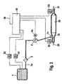
- 1 is a urea tank referred to, from which a urea-water solution over a urea line 1a with a filter screen executed filter 3 of attached to the urea tank of a metering pump 4 and to a throttle diaphragm 71 of the inlet area 70 of the catalyst assembly 30 promoted becomes.
- the pump 4 is via a stepper motor 4a speed-controlled. It is together with the throttle Inlet area 70 attached.
- the catalyst arrangement 30 has beyond Inlet area an exhaust gas supply 29 and on the opposite side an exhaust outlet 31.
- the Urea tank 1 is with a level sensor 52 and a Temperature sensor 51 provided. Temperature sensors 53 and 54 measure the temperature of the exhaust gas at the inlet or outlet of the Catalyst 30.
- An electronic control unit 40 is with sensors 51, 52 and 54 as well as with Control motor 4a of the metering pump 4 electrically connected.
- CAN data line 39 (CAN is an abbreviation for the "Controlled Area Network") is that Control unit 40 with the power supply and others electronic components in the motor vehicle, in particular the engine control unit.
- the control unit 40 detects analogously to the embodiment Figure 1 data on the engine operating state by a higher-level engine control unit via the CAN data line 39 are received, as well as the signals from temperature or Level sensors 51 to 54.
- the control unit 40 calculates from the sensor information and the information from the Engine control unit regulates the urea dosing quantity Using the metering pump 4 the required urea-water solution pressure.
- the dosing pump 4 doses for this from the control device 40 controlled stepper motor 4a driven by the required urea water solution the orifice 71 directly into the inlet area 70 on.
- the throttle diaphragm 71 supports the atomization of these Solution in the mixing chamber.
- FIG. 3 illustrates the fastening of one of the metering pumps 4 corresponding slot-controlled metering pump 80 in FIG. 2 at a cylindrical inlet area 70 ' alternative catalyst arrangement.
- the dosing pump is over a cylindrical outlet duct 83 with the inlet region connected, at the end of the outlet channel on the side of the Throttle diaphragm 71 is arranged in the inlet region.
- the Metering pump 80 is also connected via the inlet channel 84 to a Urea line connected to the urea tank 1 (see Figure 2) leads.
- the heart of the pump 4 is a cylindrical piston 81 made of a ceramic material, which rotates with a precise fit within a ceramic cylinder 82 is stored.
- the reciprocating piston has a recess 85.
- As a material for example for the ceramic piston and Ceramic cylinders find oxides like aluminum oxide or Zirconia use.
- the rotating ceramic piston 81 leads to the metering of Reducing agent cyclical strokes.
- the The stroke movement is in the axial direction of the metering pump.
- On Material transport from the inlet duct 84 into the outlet duct 83 takes place when the recess 85 is at the height of the Channels 83 and 84 are located.
- the recess 85 is so dimensioned that when they the inlet duct faces, filled by this with reducing agent can be a quarter turn further that detected reducing agent fully encloses and the piston separates the two channels from each other in a flow-tight manner and that one another quarter turn further by means of the recess transported volumes are delivered to the outlet channel can.
- the metering takes place via the speed and / or Angular velocity of the ceramic piston in the ceramic cylinder and / or via the control of the lifting movement.
- the in the Liquid flowing out of outlet channel 83 finally arrives via the throttle diaphragm 71 in the inlet area 70 'of Catalyst assembly.
- a check valve opening in the direction of flow (in 3 not shown) can be arranged.
Landscapes
- Engineering & Computer Science (AREA)
- Chemical & Material Sciences (AREA)
- Chemical Kinetics & Catalysis (AREA)
- Combustion & Propulsion (AREA)
- Health & Medical Sciences (AREA)
- General Engineering & Computer Science (AREA)
- Environmental & Geological Engineering (AREA)
- Mechanical Engineering (AREA)
- Oil, Petroleum & Natural Gas (AREA)
- General Chemical & Material Sciences (AREA)
- Analytical Chemistry (AREA)
- Biomedical Technology (AREA)
- Toxicology (AREA)
- Exhaust Gas After Treatment (AREA)
- Steering Control In Accordance With Driving Conditions (AREA)
- Filtering Of Dispersed Particles In Gases (AREA)
- Pharmaceuticals Containing Other Organic And Inorganic Compounds (AREA)
- Exhaust Gas Treatment By Means Of Catalyst (AREA)
- Nozzles (AREA)
Description
Claims (11)
- Vorrichtung zur Dosierung eines Reduktionsmittels, insbesondere eines Harnstoffs beziehungsweise einer Harnstoff-Wasser-Lösung, mit Mitteln zur Zufuhr des Reduktionsmittels in eine Katalysatoranordnung (30) zur Entfernung von Stickoxiden aus den Abgasen insbesondere eines Dieselmotors, wobei die Mittel eine Dosierpumpe (4, 4a; 80, 4a) aufweisen und sich hinter der Dosierpumpe eine Blendenanordnung (8a, 71) zur Zerstäubung des Reduktionsmittels anschließt, durch die hindurch die Zufuhr erfolgen kann, wobei die Dosierung ausschließlich mittels der Dosierpumpe erfolgt, dadurch gekennzeichnet, dass der Pumpenkopf (81, 82) der Dosierpumpe (80) und die Blendenanordnung (8a; 71) aus thermisch hochbeständigen Werkstoffen, insbesondere aus Keramik, aufgebaut sind.
- Vorrichtung nach Anspruch 1, dadurch gekennzeichnet, dass die Dosierpumpe (4, 4a; 80, 4a) mittels eines Schrittmotors (4a) ansteuerbar ist.
- Vorrichtung nach einem der vorhergehenden Ansprüche, dadurch gekennzeichnet, dass die Dosierpumpe schlitzgesteuert arbeitet.
- Vorrichtung nach einem der vorhergehenden Ansprüche, dadurch gekennzeichnet, dass die Blendenanordnung an einem Einlassbereich (70) der Katalysatoranordnung (30) angeordnet ist.
- Vorrichtung nach Anspruch 4, dadurch gekennzeichnet, dass die Blendenanordnung eine Drosselblende (71) ist.
- Vorrichtung nach einem der Ansprüche 1 bis 3, dadurch gekennzeichnet, dass die Blendenanordnung an einer Mischkammer (8) angeordnet ist, so dass das Reduktionsmittel zur Bildung eines Aerosols in die Mischkammer eingebracht werden kann.
- Vorrichtung nach Anspruch 6, dadurch gekennzeichnet, dass die Blendenanordnug eine Lochblende ist.
- Vorrichtung nach Anspruch 6 oder 7, dadurch gekennzeichnet, dass das Aerosol über eine Aerosolleitung (25) in einen Einlassbereich (70) der Katalysatoranordnung (30) einführbar ist.
- Vorrichtung nach einem der Ansprüche 6 bis 8, dadurch gekennzeichnet, dass Mittel (20, 21, 22, 23, 24, 55) zur dosierten Luftzufuhr in die Mischkammer (8) vorgesehen sind.
- Vorrichtung nach einem der vorhergehenden Ansprüche, dadurch gekennzeichnet, dass die Dosierpumpe (4, 4a; 80, 4a) an einem mit einer CAN-Datenleitung (39) verbindbaren Steuergerät (40) angeschlossen ist, so dass das Steuergerät die Dosierpumpe unter Verwertung der elektrischen Signale diverser Sensoren (51, 52, 53, 54, 55, 56) sowie an die CAN-Datenleitung angeschlossener Geräte, insbesondere eines Motorsteuergeräts, ansteuern kann.
- Vorrichtung nach einem der vorhergehenden Ansprüche, dadurch gekennzeichnet, dass zwischen der Dosierpumpe und der Blendenanordnung ein Rückschlagventil angeordnet ist.
Applications Claiming Priority (3)
| Application Number | Priority Date | Filing Date | Title |
|---|---|---|---|
| DE10047512 | 2000-09-22 | ||
| DE10047512A DE10047512A1 (de) | 2000-09-22 | 2000-09-22 | Vorrichtung zur Dosierung eines Reduktionsmittels |
| PCT/DE2001/003620 WO2002025074A1 (de) | 2000-09-22 | 2001-09-20 | Vorrichtung zur dosierung eines reduktionsmittels |
Publications (2)
| Publication Number | Publication Date |
|---|---|
| EP1218624A1 EP1218624A1 (de) | 2002-07-03 |
| EP1218624B1 true EP1218624B1 (de) | 2003-11-26 |
Family
ID=7657581
Family Applications (1)
| Application Number | Title | Priority Date | Filing Date |
|---|---|---|---|
| EP01980178A Expired - Lifetime EP1218624B1 (de) | 2000-09-22 | 2001-09-20 | Vorrichtung zur dosierung eines reduktionsmittels |
Country Status (6)
| Country | Link |
|---|---|
| EP (1) | EP1218624B1 (de) |
| JP (1) | JP2004509276A (de) |
| KR (1) | KR100859425B1 (de) |
| AT (1) | ATE255202T1 (de) |
| DE (2) | DE10047512A1 (de) |
| WO (1) | WO2002025074A1 (de) |
Families Citing this family (27)
| Publication number | Priority date | Publication date | Assignee | Title |
|---|---|---|---|---|
| ATE411468T1 (de) * | 2002-12-23 | 2008-10-15 | Grundfos Nonox As | Dosierpumpenaggregat |
| EP1676985B1 (de) * | 2003-09-30 | 2008-07-23 | Nissan Diesel Motor Co., Ltd. | Abgasentgiftungsvorrichtung für motor |
| DE10351458A1 (de) * | 2003-11-04 | 2005-06-02 | Robert Bosch Gmbh | Vorrichtung zum Einbringen eines Reduktionsmittels in das Abgas einer Brennkraftmaschine |
| ITMI20041318A1 (it) * | 2004-06-30 | 2004-09-30 | Iveco Spa | Apparecchiatura e metodfo per l'iniez<ione di un liquido ad una corrente gassosa impianto di trattamento di gas di scarico e veicolo dotato di tale impianto |
| DE102004035119C5 (de) * | 2004-07-20 | 2017-02-23 | Cummins Ltd. | Zerstäubungseinrichtung für Abgasnachbehandlungsvorrichtungen von Dieselmotoren |
| US7594393B2 (en) | 2004-09-07 | 2009-09-29 | Robert Bosch Gmbh | Apparatus for introducing a reducing agent into the exhaust of an internal combustion engine |
| AT500849B8 (de) * | 2004-11-15 | 2007-02-15 | Pankl Emission Control Systems | Harnstoffdosiervorrichtung |
| AT501091B1 (de) * | 2004-11-15 | 2006-12-15 | Pankl Emission Control Systems | Abgasreinigungsvorrichtung |
| EP1676628B1 (de) | 2004-12-30 | 2009-10-07 | Grundfos NoNox a/s | Dosierpumpenaggregat |
| DE502004005576D1 (de) | 2004-12-30 | 2008-01-03 | Grundfos Nonox As | Vorrichtung zur Erzeugung eines Reduktionsmittel-Luft-Gemisches |
| PL1676988T3 (pl) | 2004-12-30 | 2008-03-31 | Grundfos No Nox As | Agregat pompy dozującej |
| US7644576B2 (en) * | 2005-04-25 | 2010-01-12 | Ngk Spark Plug Co., Ltd. | Sensor control device |
| DE102006036017B4 (de) * | 2006-08-02 | 2008-07-31 | Haldex Brake Products Gmbh | Druckluftbereitstellungseinheit |
| DE102006036005B4 (de) * | 2006-08-02 | 2008-08-07 | Haldex Brake Products Gmbh | Druckluftventileinheit für eine Abgasbehandlungseinrichtung mit Harnstoff für Nutzfahrzeuge |
| DE102006044246B4 (de) * | 2006-09-16 | 2009-05-28 | Thomas Magnete Gmbh | Abgasnachbehandlungssystem |
| DE102007049892B4 (de) * | 2007-10-18 | 2019-12-05 | Wabco Gmbh | Kraftfahrzeug–Abgasreinigungsanlage und Verfahren zum Betreiben einer Kraftfahrzeug-Abgasreinigungsanlage |
| DE102007062704A1 (de) | 2007-12-27 | 2009-07-02 | Robert Bosch Gmbh | Vorrichtung und Verfahren zur Abgasnachbehandlung |
| DE102008013960A1 (de) * | 2008-03-12 | 2009-09-17 | Albonair Gmbh | Dosiersystem zur Eindüsung einer Harnstofflösung in den Abgasstrom eines Verbrennungsmotors |
| WO2009147146A1 (en) | 2008-06-03 | 2009-12-10 | Inergy Automotive Systems Research (Société Anonyme) | Process for starting an scr system |
| DE102009002561A1 (de) | 2009-04-22 | 2010-10-28 | Robert Bosch Gmbh | System zur Dosierung eines Reduktionsmittels |
| WO2012142745A1 (zh) * | 2011-04-19 | 2012-10-26 | 潍柴动力股份有限公司 | 用于控制柴油发动机的尿素喷射系统的设备和方法 |
| DE102012213388A1 (de) | 2012-07-31 | 2014-02-06 | Robert Bosch Gmbh | Zerstäubungsvorrichtung für eine Flüssigkeit sowie Abgasnachbehandlungsvorrichtung mit einer solchen Zerstäubungsvorrichtung |
| DE102014010250B3 (de) * | 2014-07-11 | 2015-07-23 | Thomas Magnete Gmbh | Verfahren zur Einspritzung von Flüssigkeit in den Abgasstrang eines Verbrennungsmotors |
| US9702291B2 (en) | 2015-11-03 | 2017-07-11 | Tenneco Automotive Operating Company Inc. | Exhaust aftertreatment system with ammonia gas generator |
| US10458302B2 (en) | 2015-08-20 | 2019-10-29 | Tenneco Automotive Operating Company Inc. | Exhaust aftertreatment system with ammonia gas generator |
| US9790830B2 (en) | 2015-12-17 | 2017-10-17 | Tenneco Automotive Operating Company Inc. | Exhaust after-treatment system including electrolysis generated H2 and NH3 |
| US10036291B2 (en) | 2016-01-20 | 2018-07-31 | Tenneco Automotive Operating Company Inc. | Exhaust after-treatment system including ammonia and hydrogen generation |
Family Cites Families (10)
| Publication number | Priority date | Publication date | Assignee | Title |
|---|---|---|---|---|
| SE464607B (sv) * | 1987-03-04 | 1991-05-27 | Agri Futura Ab | Doseringsutrustning till lantbrukssprutor foer spridning av pesticider paa faelt och vaexter |
| DE3829679A1 (de) * | 1988-09-01 | 1990-03-08 | Pierburg Gmbh | Dosier-verteilerpumpe fuer eine brennkraftmaschine |
| DE3830045C2 (de) * | 1988-09-03 | 1993-09-30 | Bayer Ag | Verfahren zur Reduktion von in Abgasen enthaltenen Stickoxiden mittels eines zeolithhaltigen Katalysators |
| GB2257696B (en) * | 1991-06-28 | 1995-05-31 | Riken Kk | Method and apparatus for cleaning exhaust gas |
| DE4230056A1 (de) * | 1992-09-08 | 1994-03-10 | Man Nutzfahrzeuge Ag | Zerstäubereinrichtung |
| DE4404617C2 (de) * | 1994-02-14 | 1998-11-05 | Daimler Benz Ag | Vorrichtung zur selektiven katalysierten NO¶x¶-Reduktion in sauerstoffhaltigen Abgasen von Brennkraftmaschinen |
| US5943858A (en) * | 1995-05-19 | 1999-08-31 | Siemens Aktiengesellschaft | Premixing chamber for an exhaust gas purification system |
| US5890413A (en) * | 1997-01-08 | 1999-04-06 | Generac Portable Products, Llc | Piston for water pump and related method |
| DE19819579C1 (de) * | 1998-04-30 | 1999-09-30 | Siemens Ag | Verfahren und Vorrichtung zur Abgasnachbehandlung für eine mit einem SCR-Katalysator ausgestattete Brennkraftmaschine |
| US6470673B1 (en) * | 2000-02-22 | 2002-10-29 | Ford Global Technologies, Inc. | Control of a NOX reductant delivery system |
-
2000
- 2000-09-22 DE DE10047512A patent/DE10047512A1/de not_active Withdrawn
-
2001
- 2001-09-20 KR KR1020027006459A patent/KR100859425B1/ko not_active Expired - Fee Related
- 2001-09-20 WO PCT/DE2001/003620 patent/WO2002025074A1/de not_active Ceased
- 2001-09-20 DE DE50101027T patent/DE50101027D1/de not_active Expired - Lifetime
- 2001-09-20 EP EP01980178A patent/EP1218624B1/de not_active Expired - Lifetime
- 2001-09-20 JP JP2002528652A patent/JP2004509276A/ja not_active Withdrawn
- 2001-09-20 AT AT01980178T patent/ATE255202T1/de active
Also Published As
| Publication number | Publication date |
|---|---|
| DE50101027D1 (de) | 2004-01-08 |
| JP2004509276A (ja) | 2004-03-25 |
| WO2002025074A1 (de) | 2002-03-28 |
| KR100859425B1 (ko) | 2008-09-23 |
| EP1218624A1 (de) | 2002-07-03 |
| KR20020053869A (ko) | 2002-07-05 |
| DE10047512A1 (de) | 2002-08-22 |
| ATE255202T1 (de) | 2003-12-15 |
Similar Documents
| Publication | Publication Date | Title |
|---|---|---|
| WO2002025074A1 (de) | Vorrichtung zur dosierung eines reduktionsmittels | |
| EP1430204B1 (de) | Reduktionsmittelpumpe für eine abgasnachbehandlungsanlage einer brennkraftmaschine | |
| EP1322843B1 (de) | Vorrichtung zur dosierung eines reduktionsmittels | |
| EP2061956B1 (de) | Abgasnachbehandlungssystem | |
| WO2000079108A1 (de) | Vorrichtung zur dosierung eines reduktionsmittels | |
| EP1322402A1 (de) | Verfahren und vorrichtung zur dosierung eines reduktionsmittels zur entfernung von stickoxiden aus abgasen | |
| EP1380733A2 (de) | Einrichtung zur Abgasnachbehandlung von Kraftfahrzeugen, insbesondere Dieselkraftfahrzeugen | |
| EP1238186B1 (de) | Vorrichtung zum nachbehandeln von abgasen einer brennkraftmaschine | |
| EP1456540A1 (de) | Membranpumpe mit integriertem drucksensor | |
| EP2505804B1 (de) | Dosiersystem für ein flüssiges Medium, insbesondere eine Harnstoff-Wasser-Lösung | |
| DE10035678A1 (de) | On-Board-System für die Zufuhr von Reduktionsmitteln | |
| DE602004011788T2 (de) | Dosierpumpe für ein flüssigbrennstoffadditiv | |
| WO2008031418A2 (de) | Membranpumpe | |
| EP1325217A1 (de) | Vorrichtung zur erzeugung eines reduktionsmittel-luft-gemisches | |
| EP2864602B1 (de) | Dosiersystem zur eindüsung eines reduktionsmittels in eine abgasleitung einer brennkraftmaschine | |
| DE102007016004B4 (de) | Dosiervorrichtung zum dosierten Einspritzen von Abgasnachbehandlungsmittel in eine Abgasanlage eines Verbrennungsmotors | |
| EP2761147B1 (de) | Verbrennungsanordnung mit einer brennkraftmaschine und einem abgaskanal sowie verfahren zur abgasnachbehandlung einer brennkraftmaschine | |
| DE102014010249A1 (de) | Vorrichtung und Verfahren zur Einspritzung von Flüssigkeit in den Abgasstrang eines Verbrennungsmotors | |
| EP2825740B1 (de) | Dosiervorrichtung | |
| DE102024203402B4 (de) | Verfahren zur Bestimmung einer Systemsteifigkeit | |
| DE3429129C2 (de) | Dosiervorrichtung zur Zumessung von Flüssigkeitsmengen | |
| DE102009021815B4 (de) | Förderpumpe | |
| WO2013092957A1 (de) | Fördereinrichtung und dosieranordnung |
Legal Events
| Date | Code | Title | Description |
|---|---|---|---|
| PUAI | Public reference made under article 153(3) epc to a published international application that has entered the european phase |
Free format text: ORIGINAL CODE: 0009012 |
|
| AK | Designated contracting states |
Kind code of ref document: A1 Designated state(s): AT BE CH CY DE DK ES FI FR GB GR IE IT LI LU MC NL PT SE TR |
|
| AX | Request for extension of the european patent |
Free format text: AL;LT;LV;MK;RO;SI |
|
| RIN1 | Information on inventor provided before grant (corrected) |
Inventor name: OFFENUBER, MICHAEL Inventor name: MUELLER, GERHARD Inventor name: MOELL, HELMUT Inventor name: HUBER, SVEN Inventor name: MAYER, HANSPETER Inventor name: MOELL, BRIGITTE |
|
| RIN1 | Information on inventor provided before grant (corrected) |
Inventor name: MAYER, HANSPETER Inventor name: HUBER, SVEN Inventor name: MOELL, HELMUT Inventor name: MOELL, BRIGITTE Inventor name: MUELLER, GERHARD Inventor name: OFFENUBER, MICHAEL Inventor name: MOELL, ALEXANDER |
|
| 17P | Request for examination filed |
Effective date: 20020928 |
|
| 17Q | First examination report despatched |
Effective date: 20030218 |
|
| GRAH | Despatch of communication of intention to grant a patent |
Free format text: ORIGINAL CODE: EPIDOS IGRA |
|
| RIN1 | Information on inventor provided before grant (corrected) |
Inventor name: MAYER, HANSPETER Inventor name: MOELL, ALEXANDER Inventor name: MOELL, BRIGITTE Inventor name: OFFENUBER, MICHAEL Inventor name: MOELL, HELMUT Inventor name: MUELLER, GERHARD Inventor name: HUBER, SVEN |
|
| GRAS | Grant fee paid |
Free format text: ORIGINAL CODE: EPIDOSNIGR3 |
|
| GRAA | (expected) grant |
Free format text: ORIGINAL CODE: 0009210 |
|
| AK | Designated contracting states |
Kind code of ref document: B1 Designated state(s): AT DE FR GB IT SE |
|
| REG | Reference to a national code |
Ref country code: GB Ref legal event code: FG4D Free format text: NOT ENGLISH |
|
| REF | Corresponds to: |
Ref document number: 50101027 Country of ref document: DE Date of ref document: 20040108 Kind code of ref document: P |
|
| REG | Reference to a national code |
Ref country code: IE Ref legal event code: FG4D Free format text: GERMAN |
|
| REG | Reference to a national code |
Ref country code: SE Ref legal event code: TRGR |
|
| GBT | Gb: translation of ep patent filed (gb section 77(6)(a)/1977) |
Effective date: 20040216 |
|
| LTIE | Lt: invalidation of european patent or patent extension |
Effective date: 20031126 |
|
| REG | Reference to a national code |
Ref country code: IE Ref legal event code: FD4D |
|
| ET | Fr: translation filed | ||
| PLBE | No opposition filed within time limit |
Free format text: ORIGINAL CODE: 0009261 |
|
| STAA | Information on the status of an ep patent application or granted ep patent |
Free format text: STATUS: NO OPPOSITION FILED WITHIN TIME LIMIT |
|
| 26N | No opposition filed |
Effective date: 20040827 |
|
| PGFP | Annual fee paid to national office [announced via postgrant information from national office to epo] |
Ref country code: SE Payment date: 20100921 Year of fee payment: 10 Ref country code: AT Payment date: 20100920 Year of fee payment: 10 |
|
| PGFP | Annual fee paid to national office [announced via postgrant information from national office to epo] |
Ref country code: GB Payment date: 20100924 Year of fee payment: 10 |
|
| PGFP | Annual fee paid to national office [announced via postgrant information from national office to epo] |
Ref country code: IT Payment date: 20100928 Year of fee payment: 10 |
|
| GBPC | Gb: european patent ceased through non-payment of renewal fee |
Effective date: 20110920 |
|
| PG25 | Lapsed in a contracting state [announced via postgrant information from national office to epo] |
Ref country code: IT Free format text: LAPSE BECAUSE OF NON-PAYMENT OF DUE FEES Effective date: 20110920 |
|
| REG | Reference to a national code |
Ref country code: SE Ref legal event code: EUG |
|
| PG25 | Lapsed in a contracting state [announced via postgrant information from national office to epo] |
Ref country code: GB Free format text: LAPSE BECAUSE OF NON-PAYMENT OF DUE FEES Effective date: 20110920 |
|
| REG | Reference to a national code |
Ref country code: AT Ref legal event code: MM01 Ref document number: 255202 Country of ref document: AT Kind code of ref document: T Effective date: 20110920 |
|
| PG25 | Lapsed in a contracting state [announced via postgrant information from national office to epo] |
Ref country code: AT Free format text: LAPSE BECAUSE OF NON-PAYMENT OF DUE FEES Effective date: 20110920 |
|
| PG25 | Lapsed in a contracting state [announced via postgrant information from national office to epo] |
Ref country code: SE Free format text: LAPSE BECAUSE OF NON-PAYMENT OF DUE FEES Effective date: 20110921 |
|
| REG | Reference to a national code |
Ref country code: FR Ref legal event code: PLFP Year of fee payment: 16 |
|
| PGFP | Annual fee paid to national office [announced via postgrant information from national office to epo] |
Ref country code: FR Payment date: 20160922 Year of fee payment: 16 |
|
| PGFP | Annual fee paid to national office [announced via postgrant information from national office to epo] |
Ref country code: DE Payment date: 20161125 Year of fee payment: 16 |
|
| REG | Reference to a national code |
Ref country code: DE Ref legal event code: R119 Ref document number: 50101027 Country of ref document: DE |
|
| REG | Reference to a national code |
Ref country code: FR Ref legal event code: ST Effective date: 20180531 |
|
| PG25 | Lapsed in a contracting state [announced via postgrant information from national office to epo] |
Ref country code: DE Free format text: LAPSE BECAUSE OF NON-PAYMENT OF DUE FEES Effective date: 20180404 |
|
| PG25 | Lapsed in a contracting state [announced via postgrant information from national office to epo] |
Ref country code: FR Free format text: LAPSE BECAUSE OF NON-PAYMENT OF DUE FEES Effective date: 20171002 |