EP1218125B1 - Riveting apparatus - Google Patents
Riveting apparatus Download PDFInfo
- Publication number
- EP1218125B1 EP1218125B1 EP00960895A EP00960895A EP1218125B1 EP 1218125 B1 EP1218125 B1 EP 1218125B1 EP 00960895 A EP00960895 A EP 00960895A EP 00960895 A EP00960895 A EP 00960895A EP 1218125 B1 EP1218125 B1 EP 1218125B1
- Authority
- EP
- European Patent Office
- Prior art keywords
- tool
- riveting
- reservoir
- pump
- electric motor
- Prior art date
- Legal status (The legal status is an assumption and is not a legal conclusion. Google has not performed a legal analysis and makes no representation as to the accuracy of the status listed.)
- Expired - Lifetime
Links
Images

Classifications
-
- B—PERFORMING OPERATIONS; TRANSPORTING
- B21—MECHANICAL METAL-WORKING WITHOUT ESSENTIALLY REMOVING MATERIAL; PUNCHING METAL
- B21J—FORGING; HAMMERING; PRESSING METAL; RIVETING; FORGE FURNACES
- B21J15/00—Riveting
- B21J15/10—Riveting machines
- B21J15/16—Drives for riveting machines; Transmission means therefor
- B21J15/26—Drives for riveting machines; Transmission means therefor operated by rotary drive, e.g. by electric motor
-
- B—PERFORMING OPERATIONS; TRANSPORTING
- B21—MECHANICAL METAL-WORKING WITHOUT ESSENTIALLY REMOVING MATERIAL; PUNCHING METAL
- B21J—FORGING; HAMMERING; PRESSING METAL; RIVETING; FORGE FURNACES
- B21J15/00—Riveting
- B21J15/02—Riveting procedures
- B21J15/04—Riveting hollow rivets mechanically
- B21J15/043—Riveting hollow rivets mechanically by pulling a mandrel
-
- B—PERFORMING OPERATIONS; TRANSPORTING
- B21—MECHANICAL METAL-WORKING WITHOUT ESSENTIALLY REMOVING MATERIAL; PUNCHING METAL
- B21J—FORGING; HAMMERING; PRESSING METAL; RIVETING; FORGE FURNACES
- B21J15/00—Riveting
- B21J15/10—Riveting machines
- B21J15/105—Portable riveters
-
- B—PERFORMING OPERATIONS; TRANSPORTING
- B21—MECHANICAL METAL-WORKING WITHOUT ESSENTIALLY REMOVING MATERIAL; PUNCHING METAL
- B21J—FORGING; HAMMERING; PRESSING METAL; RIVETING; FORGE FURNACES
- B21J15/00—Riveting
- B21J15/10—Riveting machines
- B21J15/16—Drives for riveting machines; Transmission means therefor
- B21J15/20—Drives for riveting machines; Transmission means therefor operated by hydraulic or liquid pressure
-
- Y—GENERAL TAGGING OF NEW TECHNOLOGICAL DEVELOPMENTS; GENERAL TAGGING OF CROSS-SECTIONAL TECHNOLOGIES SPANNING OVER SEVERAL SECTIONS OF THE IPC; TECHNICAL SUBJECTS COVERED BY FORMER USPC CROSS-REFERENCE ART COLLECTIONS [XRACs] AND DIGESTS
- Y10—TECHNICAL SUBJECTS COVERED BY FORMER USPC
- Y10T—TECHNICAL SUBJECTS COVERED BY FORMER US CLASSIFICATION
- Y10T29/00—Metal working
- Y10T29/53—Means to assemble or disassemble
- Y10T29/53709—Overedge assembling means
- Y10T29/5377—Riveter
Definitions
- the present invention relates to riveting apparatus, and more particularly to hand-held riveting apparatus of the type in which is driven by a battery-powered electric motor.
- US 5 473 805. This is a tool for riveting by means of blind breakstem rivets of the well-known type in which the rivet is placed by pulling a breakable stem with respect to a tubular body.
- the pulling head includes a reciprocable element, which is permanently connected to the electric motor by means of a mechanical gearbox, the electric motor being reversible in order to reverse the movement of the reciprocable element.
- Riveting tools according to US 5 473 805 have found acceptance in industry, but however they have the disadvantage of being relatively inefficient.
- the present invention aims to allow the design and construction of riveting apparatus which is more efficient.
- DE-U-29600615 which forms the basis for the preamble of claim 1, discloses a hand-held, battery-driven hydraulically actuated riveting tool having an electric motor-driven pump.
- the invention provides, in one of its aspects, a hand-held riveting tool as defined in claim 1 of the appended claims. Further features of the invention are defined in the various sub-claims.
- the hand-held tool of this example is conventional in its general layout. It includes a breakstem riveting head 11 with an annular nosetip anvil 12 for supporting the shell head of a blind breakstem rivet (such as that available in many countries under the Registered Trade Mark AVEX), the protruding stem of which is gripped by reciprocable jaws (not shown) carried by the forward end of a reciprocable drawbar 13.
- the rear end of the drawbar is connected to a head piston 14 reciprocable in a hydraulic cylinder 15.
- the piston 14 is actuated to place a rivet by supplying hydraulic fluid under pressure to the cylinder space 16 in front of the piston. After placing of a rivet the piston is returned forwardly by a spring 17.
- a suitable receptacle may be attached to the rear end 21 of the head, to receive broken-off parts of rivet stems.
- the operation of the riveting head 11 is conventional.
- the tool includes a reciprocating hydraulic pump 22 and a reservoir 23 for hydraulic fluid.
- the pump is operated by an eccentric cam 24, which is rotated, through a reduction gearbox 25, by means of an electric motor 26.
- When the pump is operated it draws hydraulic fluid from the reservoir 23 through an inlet non-return valve 27, and supplies hydraulic fluid to the riveting head 11 through an outlet non-return valve 28.
- a further trigger-operated reservoir inlet valve 29 is also connected, as shown in Figure 6, between the outlet side of the outlet non-return valve 28 and the reservoir 23.
- the reservoir inlet valve 29 is normally open so that it allows hydraulic fluid to flow from the head space 16, to the reservoir 23.
- the valve 29 is closed by actuation of a trigger 31 which is pivoted at 32 to the body of the tool, and carries a pair of projections 33 which contact the valve 29 in order to actuate it.
- an electrical switch 34 ( Figure 4), which is connected by means of electrical wiring (not shown) to actuate a relay 35 to connect a battery 36, housed at the bottom end of the pistol grip 18, to actuate the motor 26 to drive the pump 22.
- the arrangement of the trigger 31, valve 29 and switch 34 is such that, when the trigger 31 is progressively depressed by progressively increasing force from the finger of an operator grasping the pistol grip 18, firstly the valve 29 is closed, thereby preventing flow of hydraulic fluid into the reservoir 23, and thereafter the switch 34 is closed, thereby starting the electric motor 26 and the pump 22.
- the switch 34 opens to shut off the electric motor 26 and pump 22, and thereafter the valve 29 is opened.
- the switch 34 is mounted adjacent the valve 29, so that the actuating button 37 of the switch (see Figure 4) is actuated by a moving part of the valve 29 which is moved by operation of the trigger 31.
- FIG. 4 shows the construction and operation of the valve 29. It comprises a generally cylindrical tubular body 38 in which can reciprocate a generally cylindrical valve member 39.
- a circular inlet port 42 In the top end wall 41 of the valve body 38 is a circular inlet port 42, which can be closed by means of a conical projection 43 at the top of the valve member 39.
- the inlet port 42 When the inlet port 42 is open it communicates with a lateral outlet 44 to allow hydraulic fluid into the reservoir 23.
- a sleeve 45 Around the lower part of the valve member 39 is a sleeve 45, the lower end of which protrudes from the valve body 38 and bears against a washer 46 held on to the lower end of the valve member 39 by a circlip 47.
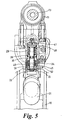
- the lower end of the sleeve 45 is enlarged into a flange 51 which has a transverse extension in the form of a lug 52 ( Figure 5).
- the trigger projections 33 contact the underside of the sleeve flange 51, and the projecting lug 52 is aligned under the switch 34 so that the lug can contact the switch button 37 to actuate the switch, as will be described later.
- valve member 39 is urged upwardly into the closed position by means of a first helical spring 48 acting between the valve body 29 and the upper end of the valve member 39. It is urged downwardly into the open position by means of a second helical spring 49, acting between the valve body 29 and the sleeve 45, and thereby through the washer 46 and circlip 47 on the valve member 39.
- FIG. 4A shows the position with the trigger 31 not operated. i.e. in its rest position; the sleeve 45 is held in its lowest position by the second spring 49, and the valve member 39 is in its lowest or open position, as explained above, and the switch 34 is not actuated, i.e. it is in its "off" position.
- FIG. 4B illustrates the valve member 39 in its fully closed position, with the conical projection 43 sealing the inlet part 42 under the urging of the first spring 47.
- the switch 34 is still not actuated, i.e. it is still in its "off" position.
- the projections 33 apply more force to the bottom of the sleeve 45, and lifts the sleeve 45 out of contact with the washer 46, whilst compressing the second spring 49 even further.
- the second spring 49 no longer has any effect in reducing the closing force exerted by the first spring 48 on the valve member 39.
- the closing force on the valve is a predetermined known value, so that the valve will operate as a pressure relief valve at a predetermined over-pressure of the hydraulic fluid. This will allow hydraulic fluid to be safely returned to the reservoir 23, regardless of sustained operation of the tool -actuating device, i.e. if the operator keeps the trigger 31 depressed for a long time so that the head piston 14 contacts the cylinder cap.
- a battery-operated hand-held riveting tool as described above is substantially more efficient than the prior art tool referred to in the preamble due to the conversion of rotary motion to linear motion by hydraulic means instead of mechanical means, and the use of a uni-directional electric motor, i.e. one which is electrically actuated so as to rotate in only one direction, i.e. to actuate the riveting head, but not to return the riveting head its initial position.
- the invention is not restricted to the details of the foregoing example.
- it could be applied to a tool for a form of riveting, other than blind breakstem riveting, e.g. blind repetition pull-through riveting, the installation of threaded inserts, or self-piercing riveting.
Abstract
Description
- The present invention relates to riveting apparatus, and more particularly to hand-held riveting apparatus of the type in which is driven by a battery-powered electric motor.
- One such form of apparatus is described in US 5 473 805. This is a tool for riveting by means of blind breakstem rivets of the well-known type in which the rivet is placed by pulling a breakable stem with respect to a tubular body. The pulling head includes a reciprocable element, which is permanently connected to the electric motor by means of a mechanical gearbox, the electric motor being reversible in order to reverse the movement of the reciprocable element. Riveting tools according to US 5 473 805 have found acceptance in industry, but however they have the disadvantage of being relatively inefficient.
- The present invention aims to allow the design and construction of riveting apparatus which is more efficient.
- DE-U-29600615, which forms the basis for the preamble of claim 1, discloses a hand-held, battery-driven hydraulically actuated riveting tool having an electric motor-driven pump.
- The invention provides, in one of its aspects, a hand-held riveting tool as defined in claim 1 of the appended claims. Further features of the invention are defined in the various sub-claims.
- A specific embodiment of the invention will be described by way of example and with reference to the accompanying drawings, in which:
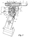
- Figure 1 is a section through a hand-held battery-powered breakstem blind riveting tool;
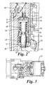
- Figure 2 is an enlargement of part of Figure 1;
- Figure 3 is a view on the line III of Figure 1;
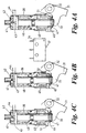
- Figures 4A, 4B and 4C show progressive positions of the reservoir inlet valve;
- Figure 5 is an enlarged, partly sectional, view in the direction of the arrow V in Figure 1; and
- Figure 6 is a schematic block diagram of the hydraulic circuitry of the tool.
-
- The hand-held tool of this example is conventional in its general layout. It includes a breakstem riveting
head 11 with anannular nosetip anvil 12 for supporting the shell head of a blind breakstem rivet (such as that available in many countries under the Registered Trade Mark AVEX), the protruding stem of which is gripped by reciprocable jaws (not shown) carried by the forward end of areciprocable drawbar 13. The rear end of the drawbar is connected to ahead piston 14 reciprocable in ahydraulic cylinder 15. Thepiston 14 is actuated to place a rivet by supplying hydraulic fluid under pressure to thecylinder space 16 in front of the piston. After placing of a rivet the piston is returned forwardly by aspring 17. A suitable receptacle (not shown) may be attached to therear end 21 of the head, to receive broken-off parts of rivet stems. The operation of the rivetinghead 11 is conventional. - The tool includes a reciprocating
hydraulic pump 22 and areservoir 23 for hydraulic fluid. The pump is operated by aneccentric cam 24, which is rotated, through areduction gearbox 25, by means of anelectric motor 26. When the pump is operated it draws hydraulic fluid from thereservoir 23 through an inletnon-return valve 27, and supplies hydraulic fluid to the rivetinghead 11 through an outletnon-return valve 28. A further trigger-operatedreservoir inlet valve 29 is also connected, as shown in Figure 6, between the outlet side of the outletnon-return valve 28 and thereservoir 23. - The
reservoir inlet valve 29 is normally open so that it allows hydraulic fluid to flow from thehead space 16, to thereservoir 23. Thevalve 29 is closed by actuation of atrigger 31 which is pivoted at 32 to the body of the tool, and carries a pair ofprojections 33 which contact thevalve 29 in order to actuate it. - Mounted adjacent the trigger-operated
valve 29 is an electrical switch 34 (Figure 4), which is connected by means of electrical wiring (not shown) to actuate arelay 35 to connect abattery 36, housed at the bottom end of thepistol grip 18, to actuate themotor 26 to drive thepump 22. - The arrangement of the
trigger 31,valve 29 andswitch 34 is such that, when thetrigger 31 is progressively depressed by progressively increasing force from the finger of an operator grasping thepistol grip 18, firstly thevalve 29 is closed, thereby preventing flow of hydraulic fluid into thereservoir 23, and thereafter theswitch 34 is closed, thereby starting theelectric motor 26 and thepump 22. When thetrigger 31 is released, firstly theswitch 34 opens to shut off theelectric motor 26 andpump 22, and thereafter thevalve 29 is opened. Moreover, it is arranged that during the time when thevalve 29 is closed as just described, nonetheless it can still operate as a pressure relief valve to relieve into the reservoir any dangerously high pressure of hydraulic fluid which may build up. As previously mentioned, theswitch 34 is mounted adjacent thevalve 29, so that theactuating button 37 of the switch (see Figure 4) is actuated by a moving part of thevalve 29 which is moved by operation of thetrigger 31. - Figure 4 shows the construction and operation of the
valve 29. It comprises a generally cylindricaltubular body 38 in which can reciprocate a generallycylindrical valve member 39. In thetop end wall 41 of thevalve body 38 is acircular inlet port 42, which can be closed by means of aconical projection 43 at the top of thevalve member 39. When theinlet port 42 is open it communicates with alateral outlet 44 to allow hydraulic fluid into thereservoir 23. Around the lower part of thevalve member 39 is asleeve 45, the lower end of which protrudes from thevalve body 38 and bears against awasher 46 held on to the lower end of thevalve member 39 by acirclip 47. The lower end of thesleeve 45 is enlarged into aflange 51 which has a transverse extension in the form of a lug 52 (Figure 5). Thetrigger projections 33 contact the underside of thesleeve flange 51, and the projectinglug 52 is aligned under theswitch 34 so that the lug can contact theswitch button 37 to actuate the switch, as will be described later. - The
valve member 39 is urged upwardly into the closed position by means of a firsthelical spring 48 acting between thevalve body 29 and the upper end of thevalve member 39. It is urged downwardly into the open position by means of a secondhelical spring 49, acting between thevalve body 29 and thesleeve 45, and thereby through thewasher 46 and circlip 47 on thevalve member 39. - The two
springs 48 & 49 are identical, so that thevalve member 39 is normally held "floating" in the open position, as shown in Figure 4A. Figures 4A, 4B and 4C are aligned vertically with each other to illustrate the relative positions of thesleeve 45,valve member 39 and trigger 31 at different stages in the progressive operation of thetrigger 31. Figure 4 also illustrates the relative vertical alignment (but not the horizontal alignment) of theswitch 34 and itsbutton 37. Figure 4A shows the position with thetrigger 31 not operated. i.e. in its rest position; thesleeve 45 is held in its lowest position by thesecond spring 49, and thevalve member 39 is in its lowest or open position, as explained above, and theswitch 34 is not actuated, i.e. it is in its "off" position. - When the operator actuates the trigger by applying a progressively increasing force to it, the
projections 33 bear on theflange 51 of thesleeve 45, to push it upwards, thus progressively compressing thesecond spring 49 and allowing thefirst spring 48 to progressively push the valve member upwards, towards its closed position. Figure 4B illustrates thevalve member 39 in its fully closed position, with theconical projection 43 sealing theinlet part 42 under the urging of thefirst spring 47. Theswitch 34 is still not actuated, i.e. it is still in its "off" position. - As the operator applies still more force to the
trigger 31, theprojections 33 apply more force to the bottom of thesleeve 45, and lifts thesleeve 45 out of contact with thewasher 46, whilst compressing thesecond spring 49 even further. When thesleeve 45 has left contact with thewasher 46, thesecond spring 49 no longer has any effect in reducing the closing force exerted by thefirst spring 48 on thevalve member 39. Hence the closing force on the valve is a predetermined known value, so that the valve will operate as a pressure relief valve at a predetermined over-pressure of the hydraulic fluid. This will allow hydraulic fluid to be safely returned to thereservoir 23, regardless of sustained operation of the tool -actuating device, i.e. if the operator keeps thetrigger 31 depressed for a long time so that thehead piston 14 contacts the cylinder cap. - As the
sleeve 49 continues to rise in this way, its projectinglug 52 actuates thebutton 37 of theswitch 34. This starts theelectric motor 26, which operates thepump 22. This applies hydraulic fluid under pressure to thespace 16 on the pullinghead 11, thus actuating the head mechanism to place a rivet, thedrawbar 13 being retracted against the urging ofspring 17. When the rivet has been placed, the operator releases the force on thetrigger 31. The sequence of movements described above is reversed. Firstly thesleeve 45 descends, allowing theswitch 34 to turn off and stop thepump 28. Then thevalve member 39 is allowed to move away from theinlet part 42, thus allowing hydraulic fluid to be ejected from thehead cylinder space 16 bypiston 14 under the urging ofspring 17, and into thereservoir 23. Thepiston 14,drawbar 13 and the riveting head are thus returned to their initial positions by thespring 17, and not by theelectric motor 26. Thus the electric motor, in use, rotates in only one direction. Thevalve 29 returns to its rest position illustrated in Figure 4A. - It is found that a battery-operated hand-held riveting tool as described above is substantially more efficient than the prior art tool referred to in the preamble due to the conversion of rotary motion to linear motion by hydraulic means instead of mechanical means, and the use of a uni-directional electric motor, i.e. one which is electrically actuated so as to rotate in only one direction, i.e. to actuate the riveting head, but not to return the riveting head its initial position.
- The invention is not restricted to the details of the foregoing example. For instance, it could be applied to a tool for a form of riveting, other than blind breakstem riveting, e.g. blind repetition pull-through riveting, the installation of threaded inserts, or self-piercing riveting.
Claims (9)
- A hand-held riveting tool driven by a battery-powered electric motor (26), comprising a hydraulically-actuated riveting head (11), and a hydraulic pump (22) driven by the electric motor (26), whereby when the motor (26) is operated it drives the hydraulic pump (22) to actuate the riveting head (11), the tool including a tool-actuating device such as a trigger (31), and also including a reservoir (23) for hydraulic fluid, the riveting tool being characterized in that the hydraulic supply line from the pump (22) to the riveting head (11) is connected to the reservoir (23) by a reservoir inlet valve (29) which is normally open to allow hydraulic fluid to flow from the supply line into the reservoir (23), in which operation of the tool-actuating device (31) firstly closes the reservoir inlet valve (29), and then switches on the electric motor (26) to operate the pump (22).
- A riveting tool as claimed in claim 1, in which release of the tool-actuating device (31) firstly switches off the electric motor (26) to stop operation of the pump (22), and then opens the reservoir inlet valve (29).
- A riveting tool as claimed in claim 1 or claim 2, in which the reservoir inlet valve (29) when closed by operation of the tool-actuating device (31) as aforesaid also acts as a pressure-relief valve to relieve over-pressure of hydraulic fluid.
- A riveting tool as claimed in claim 3 in which the reservoir inlet valve (29) is urged closed by a first spring (48) with a first predetermined force and is urged open by a second spring (49) with a second predetermined force, operation of the tool-actuating device (31) removing the action of the second predetermined force, whereby the valve (29) is thereafter held closed by the first predetermined force regardless of sustained operation of the tool-actuating device (31), thereby to provide a predetermined pressure at which the valve (29) acts as a pressure relief valve as aforesaid.
- A riveting tool as claimed in any of the preceding claims in which the riveting head (11) is adapted to place blind breakstem rivets.
- A riveting tool as claimed in any of the preceding claims, in which after the motor (26) has been operated to actuate the riveting head (11) as aforesaid and is then switched off, the riveting head (11) is returned to its initial position by means independent of the head actuating means.
- A riveting tool as claimed in claim 6, in which the head (11) is returned to its initial position by means of a spring (17).
- A riveting tool as claimed in any of the preceding claims, in which the electric motor (26), in use, rotates in only one direction.
- A riveting tool as claimed in any of the preceding claims, in which the hydraulic pump (22) is a reciprocating pump.
Applications Claiming Priority (3)
| Application Number | Priority Date | Filing Date | Title |
|---|---|---|---|
| GBGB9923266.2A GB9923266D0 (en) | 1999-10-02 | 1999-10-02 | Riveting apparatus |
| GB9923266 | 1999-10-02 | ||
| PCT/GB2000/003703 WO2001024956A1 (en) | 1999-10-02 | 2000-09-27 | Riveting apparatus |
Publications (2)
| Publication Number | Publication Date |
|---|---|
| EP1218125A1 EP1218125A1 (en) | 2002-07-03 |
| EP1218125B1 true EP1218125B1 (en) | 2004-11-24 |
Family
ID=10861968
Family Applications (1)
| Application Number | Title | Priority Date | Filing Date |
|---|---|---|---|
| EP00960895A Expired - Lifetime EP1218125B1 (en) | 1999-10-02 | 2000-09-27 | Riveting apparatus |
Country Status (10)
| Country | Link |
|---|---|
| US (1) | US6886226B1 (en) |
| EP (1) | EP1218125B1 (en) |
| JP (1) | JP3875557B2 (en) |
| KR (1) | KR100613551B1 (en) |
| AU (1) | AU773183B2 (en) |
| CA (1) | CA2385934C (en) |
| DE (1) | DE60016267T2 (en) |
| ES (1) | ES2231255T3 (en) |
| GB (1) | GB9923266D0 (en) |
| WO (1) | WO2001024956A1 (en) |
Cited By (1)
| Publication number | Priority date | Publication date | Assignee | Title |
|---|---|---|---|---|
| CN103072124A (en) * | 2012-12-27 | 2013-05-01 | 台州巨力工具有限公司 | Electric hydraulic tool |
Families Citing this family (22)
| Publication number | Priority date | Publication date | Assignee | Title |
|---|---|---|---|---|
| DE112005002804B4 (en) * | 2004-11-19 | 2014-07-31 | Richard Bergner Verbindungstechnik Gmbh & Co. Kg | Hydraulic unit and method for providing pressurized hydraulic fluid |
| GB2424609B (en) * | 2005-04-02 | 2007-10-24 | Textron Fastening Syst Ltd | Fastener installation tool including means for disabling the tool |
| GB2447413B (en) * | 2007-03-16 | 2009-03-18 | Avdel Uk Ltd | Fastener installation tool |
| US9370820B2 (en) | 2007-03-16 | 2016-06-21 | Avdel Uk Limited | Fastener installation tool |
| KR100980088B1 (en) * | 2007-12-06 | 2010-09-06 | 이수일 | Electric apparatus for riveting |
| ITBO20080117A1 (en) * | 2008-02-21 | 2009-08-22 | Ober S P A | ELECTRO-HYDRAULIC PISTOL DEVICE WITH ELECTRONIC CONTROL FOR THE DEFORMATION OF FIXING ELEMENTS |
| TW201021938A (en) * | 2008-12-09 | 2010-06-16 | Tranmax Machinery Co Ltd | Riveting tool having rivet stem removal function |
| KR101017257B1 (en) * | 2008-12-30 | 2011-02-28 | 주식회사 성우하이텍 | Module cylinder in self-piercing rivet system |
| JP5674691B2 (en) * | 2012-02-23 | 2015-02-25 | 株式会社ロブテックス | Electric riveter |
| KR101452597B1 (en) * | 2012-12-28 | 2014-10-21 | 한국산업기술대학교산학협력단 | Electrically powered rivet gun apparatus |
| EP2786843B1 (en) * | 2013-04-02 | 2019-09-25 | Dubuis et Cie S.A.S. | A battery powered crimping tool |
| CN103671329B (en) * | 2013-12-23 | 2016-09-07 | 台州巨力工具有限公司 | Open type hydraulic control valve |
| US20150305318A1 (en) | 2014-04-23 | 2015-10-29 | William R. Moriarty | Furniture Protector against Crawling Arthropods |
| CN105459031B (en) * | 2015-10-21 | 2017-07-07 | 国网浙江富阳市供电公司 | A kind of charging type hydraulic tool |
| EP3370896B1 (en) * | 2015-11-02 | 2022-03-23 | Olsson, Gorn | Handheld handle-powered pull riveter |
| CN106032815B (en) * | 2016-01-25 | 2017-10-24 | 重庆三峡学院 | Cylinder body structure suitable for miniature electro-hydraulic clamp body |
| EP3519123B1 (en) | 2016-09-30 | 2023-11-01 | Apex Brands, Inc. | Portable hydraulic power tool |
| US11673243B2 (en) | 2018-09-05 | 2023-06-13 | Milwaukee Electric Tool Corporation | Blind rivet nut-setting tool |
| CN219632508U (en) | 2020-06-03 | 2023-09-05 | 米沃奇电动工具公司 | Rivet tool and power tool for setting rivets |
| EP4008482B1 (en) | 2020-12-07 | 2023-10-11 | Dubuis et Cie | Joining tool for joining a deformable element to a workpiece |
| IT202100010556A1 (en) * | 2021-04-27 | 2022-10-27 | Ober S P A | PORTABLE EQUIPMENT |
| CN114643330A (en) * | 2022-03-18 | 2022-06-21 | 眉山中车紧固件科技有限公司 | Reinforcing steel bar rivet withdrawing system |
Family Cites Families (19)
| Publication number | Priority date | Publication date | Assignee | Title |
|---|---|---|---|---|
| US3254522A (en) * | 1964-01-29 | 1966-06-07 | United Shoe Machinery Corp | Hydraulic pop riveters |
| US3502028A (en) * | 1968-02-08 | 1970-03-24 | Sargent Industries | Hydraulic motor and pump |
| US3616673A (en) * | 1969-08-12 | 1971-11-02 | Louis F Miklos | Combination rotating and reciprocating rivet tool |
| FR2582561A1 (en) * | 1985-05-31 | 1986-12-05 | Courtois Alain | Portable compression tool |
| US5195354A (en) * | 1989-03-31 | 1993-03-23 | Japan Storage Battery Co., Ltd. | Cam crank mechanism and motor driven hydraulic tool |
| DE4126602A1 (en) | 1991-08-12 | 1993-02-18 | Gesipa Blindniettechnik | BLIND RIVET DEVICE |
| US5553478A (en) * | 1994-04-08 | 1996-09-10 | Burndy Corporation | Hand-held compression tool |
| GB2301547A (en) | 1995-06-02 | 1996-12-11 | Avdel Systems Ltd | Fastener installation tool |
| DE29600615U1 (en) * | 1996-01-18 | 1996-10-24 | Eckold Vorrichtung | Electrohydraulic handheld device |
| US5706541A (en) * | 1996-04-29 | 1998-01-13 | Black & Decker Inc. | Watertight friction fit battery cap with cam removal |
| US5682659A (en) | 1996-08-16 | 1997-11-04 | Chang; Ching-Tsung | Hand blind riveter |
| JP3792307B2 (en) * | 1996-08-26 | 2006-07-05 | 株式会社オグラ | Hydraulic actuator |
| DE19645643A1 (en) * | 1996-11-06 | 1998-05-07 | Braun Ag | Pressure relief valve for an oral irrigator |
| US5953822A (en) * | 1996-12-24 | 1999-09-21 | Rescue Technology, Inc. | Rescue tool |
| ATE215273T1 (en) * | 1997-10-15 | 2002-04-15 | Klauke Gmbh Gustav | HYDRAULIC PRESSING DEVICE |
| DE19806051A1 (en) | 1998-02-13 | 1999-08-26 | Honsel M H Beteiligungs Gmbh | Rivet setting tool |
| FR2779670B1 (en) * | 1998-06-15 | 2000-08-04 | Jean Claude Joux | ELECTROPORTATIVE APPARATUS FOR TIGHTENING NUTS OR CRIMPING BLIND RIVET WITH ROD BREAKING |
| DE19903020A1 (en) * | 1999-01-26 | 2000-08-03 | Honsel M H Beteiligungs Gmbh | Rivet setting tool |
| US6148507A (en) * | 1999-03-12 | 2000-11-21 | Swanson; Jeffery S | Machine for pressing a fastener through sheet metal studs |
-
1999
- 1999-10-02 GB GBGB9923266.2A patent/GB9923266D0/en not_active Ceased
-
2000
- 2000-09-27 DE DE60016267T patent/DE60016267T2/en not_active Expired - Lifetime
- 2000-09-27 US US10/089,490 patent/US6886226B1/en not_active Expired - Fee Related
- 2000-09-27 WO PCT/GB2000/003703 patent/WO2001024956A1/en not_active Application Discontinuation
- 2000-09-27 CA CA002385934A patent/CA2385934C/en not_active Expired - Fee Related
- 2000-09-27 AU AU73052/00A patent/AU773183B2/en not_active Ceased
- 2000-09-27 EP EP00960895A patent/EP1218125B1/en not_active Expired - Lifetime
- 2000-09-27 JP JP2001527941A patent/JP3875557B2/en not_active Expired - Fee Related
- 2000-09-27 ES ES00960895T patent/ES2231255T3/en not_active Expired - Lifetime
- 2000-09-27 KR KR1020027004247A patent/KR100613551B1/en not_active IP Right Cessation
Cited By (2)
| Publication number | Priority date | Publication date | Assignee | Title |
|---|---|---|---|---|
| CN103072124A (en) * | 2012-12-27 | 2013-05-01 | 台州巨力工具有限公司 | Electric hydraulic tool |
| CN103072124B (en) * | 2012-12-27 | 2015-11-18 | 台州巨力工具有限公司 | A kind of Electric hydraulic tool |
Also Published As
| Publication number | Publication date |
|---|---|
| US6886226B1 (en) | 2005-05-03 |
| CA2385934A1 (en) | 2001-04-12 |
| DE60016267T2 (en) | 2005-12-01 |
| CA2385934C (en) | 2007-06-19 |
| KR20020075854A (en) | 2002-10-07 |
| KR100613551B1 (en) | 2006-08-16 |
| ES2231255T3 (en) | 2005-05-16 |
| AU7305200A (en) | 2001-05-10 |
| EP1218125A1 (en) | 2002-07-03 |
| JP2003511237A (en) | 2003-03-25 |
| JP3875557B2 (en) | 2007-01-31 |
| GB9923266D0 (en) | 1999-12-08 |
| AU773183B2 (en) | 2004-05-20 |
| DE60016267D1 (en) | 2004-12-30 |
| WO2001024956A1 (en) | 2001-04-12 |
Similar Documents
| Publication | Publication Date | Title |
|---|---|---|
| EP1218125B1 (en) | Riveting apparatus | |
| US10589409B2 (en) | Cordless carton closing tool and method of replacing a carton closer clinching member | |
| EP2313236B1 (en) | Tool head assemblies for pressing devices | |
| JP4083383B2 (en) | Pneumatic-operating hydraulic rivet gun | |
| US3661313A (en) | Power device having improved feed mechanism | |
| US7788962B2 (en) | Hydraulic tool | |
| US6684470B1 (en) | Electroportable device for placing clinch-on nuts or break-off stem blind rivets | |
| US20050120770A1 (en) | Electrohydraulic pressing device and method for operating the same | |
| EP2163771B1 (en) | Hydraulic tool having a single hydraulic fluid suction line from the reservoir to a ram or to a mechanical actuator. | |
| JP2003511237A5 (en) | ||
| US4821555A (en) | Hydropneumatic gun for setting blind-rivet nuts | |
| JPS62296925A (en) | Hydraulic crimp working tool | |
| EP1206337A2 (en) | Fastener driving device with enhanced magazine latch assembly | |
| JPH0741362B2 (en) | Blind rivet continuous caulking method and continuous riveter | |
| JPH0464835B2 (en) | ||
| JPH10109280A (en) | Driving machine | |
| CA1300564C (en) | Hydropneumatic gun for setting blind-rivet nuts | |
| JPH0118293Y2 (en) | ||
| JPH06126492A (en) | Portable hydraulic tool | |
| JPH085028Y2 (en) | Hydraulic tool with built-in bite release mechanism | |
| JPH0723087Y2 (en) | Riveter | |
| WO1979000531A1 (en) | Hydraulic nailing pistol |
Legal Events
| Date | Code | Title | Description |
|---|---|---|---|
| PUAI | Public reference made under article 153(3) epc to a published international application that has entered the european phase |
Free format text: ORIGINAL CODE: 0009012 |
|
| 17P | Request for examination filed |
Effective date: 20020410 |
|
| AK | Designated contracting states |
Kind code of ref document: A1 Designated state(s): AT BE CH CY DE DK ES FI FR GB GR IE IT LI LU MC NL PT SE |
|
| AX | Request for extension of the european patent |
Free format text: AL;LT;LV;MK;RO;SI |
|
| 17Q | First examination report despatched |
Effective date: 20030905 |
|
| GRAP | Despatch of communication of intention to grant a patent |
Free format text: ORIGINAL CODE: EPIDOSNIGR1 |
|
| RBV | Designated contracting states (corrected) |
Designated state(s): AT BE CH CY DE ES FR GB IT LI |
|
| RBV | Designated contracting states (corrected) |
Designated state(s): DE ES FR GB IT |
|
| GRAA | (expected) grant |
Free format text: ORIGINAL CODE: 0009210 |
|
| GRAS | Grant fee paid |
Free format text: ORIGINAL CODE: EPIDOSNIGR3 |
|
| AK | Designated contracting states |
Kind code of ref document: B1 Designated state(s): DE ES FR GB IT |
|
| REG | Reference to a national code |
Ref country code: GB Ref legal event code: FG4D |
|
| REF | Corresponds to: |
Ref document number: 60016267 Country of ref document: DE Date of ref document: 20041230 Kind code of ref document: P |
|
| REG | Reference to a national code |
Ref country code: IE Ref legal event code: FG4D |
|
| REG | Reference to a national code |
Ref country code: ES Ref legal event code: FG2A Ref document number: 2231255 Country of ref document: ES Kind code of ref document: T3 |
|
| PLBE | No opposition filed within time limit |
Free format text: ORIGINAL CODE: 0009261 |
|
| STAA | Information on the status of an ep patent application or granted ep patent |
Free format text: STATUS: NO OPPOSITION FILED WITHIN TIME LIMIT |
|
| ET | Fr: translation filed | ||
| 26N | No opposition filed |
Effective date: 20050825 |
|
| REG | Reference to a national code |
Ref country code: FR Ref legal event code: CD Ref country code: FR Ref legal event code: CA |
|
| PGFP | Annual fee paid to national office [announced via postgrant information from national office to epo] |
Ref country code: ES Payment date: 20101018 Year of fee payment: 11 |
|
| REG | Reference to a national code |
Ref country code: ES Ref legal event code: FD2A Effective date: 20130823 |
|
| PG25 | Lapsed in a contracting state [announced via postgrant information from national office to epo] |
Ref country code: ES Free format text: LAPSE BECAUSE OF NON-PAYMENT OF DUE FEES Effective date: 20110928 |
|
| PGFP | Annual fee paid to national office [announced via postgrant information from national office to epo] |
Ref country code: DE Payment date: 20130923 Year of fee payment: 14 |
|
| PGFP | Annual fee paid to national office [announced via postgrant information from national office to epo] |
Ref country code: FR Payment date: 20130918 Year of fee payment: 14 Ref country code: GB Payment date: 20130925 Year of fee payment: 14 |
|
| PGFP | Annual fee paid to national office [announced via postgrant information from national office to epo] |
Ref country code: IT Payment date: 20130926 Year of fee payment: 14 |
|
| REG | Reference to a national code |
Ref country code: DE Ref legal event code: R119 Ref document number: 60016267 Country of ref document: DE |
|
| GBPC | Gb: european patent ceased through non-payment of renewal fee |
Effective date: 20140927 |
|
| REG | Reference to a national code |
Ref country code: FR Ref legal event code: ST Effective date: 20150529 |
|
| PG25 | Lapsed in a contracting state [announced via postgrant information from national office to epo] |
Ref country code: GB Free format text: LAPSE BECAUSE OF NON-PAYMENT OF DUE FEES Effective date: 20140927 Ref country code: DE Free format text: LAPSE BECAUSE OF NON-PAYMENT OF DUE FEES Effective date: 20150401 |
|
| PG25 | Lapsed in a contracting state [announced via postgrant information from national office to epo] |
Ref country code: FR Free format text: LAPSE BECAUSE OF NON-PAYMENT OF DUE FEES Effective date: 20140930 Ref country code: IT Free format text: LAPSE BECAUSE OF NON-PAYMENT OF DUE FEES Effective date: 20140927 |