EP1217307B1 - Wrasenleitschirm für eine Dunstabzugshaube - Google Patents
Wrasenleitschirm für eine Dunstabzugshaube Download PDFInfo
- Publication number
- EP1217307B1 EP1217307B1 EP01127670A EP01127670A EP1217307B1 EP 1217307 B1 EP1217307 B1 EP 1217307B1 EP 01127670 A EP01127670 A EP 01127670A EP 01127670 A EP01127670 A EP 01127670A EP 1217307 B1 EP1217307 B1 EP 1217307B1
- Authority
- EP
- European Patent Office
- Prior art keywords
- screen
- extractor hood
- receiving strip
- strip
- fume extractor
- Prior art date
- Legal status (The legal status is an assumption and is not a legal conclusion. Google has not performed a legal analysis and makes no representation as to the accuracy of the status listed.)
- Expired - Lifetime
Links
- 239000003517 fume Substances 0.000 claims description 6
- 230000007246 mechanism Effects 0.000 claims description 4
- XAGFODPZIPBFFR-UHFFFAOYSA-N aluminium Chemical compound [Al] XAGFODPZIPBFFR-UHFFFAOYSA-N 0.000 claims description 3
- 229910052782 aluminium Inorganic materials 0.000 claims description 3
- 239000011521 glass Substances 0.000 claims description 2
- 210000003414 extremity Anatomy 0.000 claims 3
- 239000004411 aluminium Substances 0.000 claims 1
- 210000001364 upper extremity Anatomy 0.000 claims 1
- 239000000463 material Substances 0.000 description 2
- 230000007704 transition Effects 0.000 description 2
- 101100390736 Danio rerio fign gene Proteins 0.000 description 1
- 101100390738 Mus musculus Fign gene Proteins 0.000 description 1
- 239000000853 adhesive Substances 0.000 description 1
- 230000001070 adhesive effect Effects 0.000 description 1
- 230000032683 aging Effects 0.000 description 1
- 238000010411 cooking Methods 0.000 description 1
- 230000000694 effects Effects 0.000 description 1
- 239000004519 grease Substances 0.000 description 1
- 238000003780 insertion Methods 0.000 description 1
- 230000037431 insertion Effects 0.000 description 1
- 239000000700 radioactive tracer Substances 0.000 description 1
- 230000000007 visual effect Effects 0.000 description 1
Images

Classifications
-
- F—MECHANICAL ENGINEERING; LIGHTING; HEATING; WEAPONS; BLASTING
- F24—HEATING; RANGES; VENTILATING
- F24C—DOMESTIC STOVES OR RANGES ; DETAILS OF DOMESTIC STOVES OR RANGES, OF GENERAL APPLICATION
- F24C15/00—Details
- F24C15/20—Removing cooking fumes
Definitions
- the invention relates to a Wrasenleitrate for an extractor hood, wherein the screen is arranged with one side in a clamping connection of a receiving strip.
- Extractor hoods which are mounted under a wall unit, have a vapor control screen.
- This Wrasenleitrate has the task to direct the fumes or steam of the cooking zones in the suction of the hood.
- the prior art discloses three types of vapor control screens, rigid fixed vapor guidance screens, retractable vapor guidance screens and retractable vapor guidance screens.
- the market mainly uses retractable vapor control screens.
- a screen is arranged in side panels right and left and the side panels rotatably supported in a spring profile.
- a rest stop is incorporated in the side parts, so that the vapor tracer can be brought into different positions.
- the side panels are there to enclose the screen right and left and thereby keep safe.
- Object of the present invention was to provide a secure attitude for the screen of a Wrasenleitles, which should also ensure the use of different shapes for the Wrasenleittransport.
- the object is achieved with a Wrasenleitconnect with the features of claim 1.
- the legs of the U-shaped receptacle of the receiving strip are provided with chamfers for better insertion of the screen during assembly.
- a clamping element is arranged on one of the legs.
- the receiving strip is preferably arranged on the rear side of the screen. It is designed so that it has a two-leg U-shaped receptacle for the arrangement of the screen.
- the receiving bar is arranged in a bearing which is arranged in a spring profile, wherein the spring profile is either itself provided with locking mechanisms or with detent mechanisms of the hood is in operative connection to allow adjustment of the Wrasenleitless.
- the screen 1 is arranged in a two-leg U-shaped receptacle 5 of the receiving strip 2. Both legs of the U-shaped receptacle 5 of the receiving strip 2 are provided with chamfers for better introduction of the screen 1 during assembly. In a further embodiment, however, it is also conceivable to provide only one of the legs with a run-on slope.
- the upper leg of the U-shaped receptacle 5 of the receiving strip 2, which is arranged at the top of the screen 1, is provided with a clamping element 6.
- the clamping element 6 is wedge-shaped.
- a clamping element 6 in semicircular shape, circle segment shape, etc.
- attachment of the screen 1 at the upper edge in the receiving bar 2 eliminates the visually disturbing lying in the main visual range transition between the screen 1 and in the prior art usual side brackets.
- the screen 1 only needs a straight edge, the other edges can be beautifully designed oblique or rounded.
- the receiving strip 2 is made of an aluminum extruded part. This part can be produced with the necessary accuracy and thus ensures a secure clamping of the screen 1.
- the screen 1 is held in the receiving bar 2 exclusively by the clamp connection.
- An adhesive bond is not necessary and not possible, since splices on cooker hoods from the fat of the wrestling can be easily destroyed.
- Aluminum is also very resistant to temperature, grease and aging under the operating conditions of cooker hoods.
- the screen 1 in the embodiment is made of glass. However, other materials are possible for other embodiments.
- the receiving strip 2 is profiled at the top, round in the exemplary embodiment, designed to allow a secure and easy attachment in a laterally arrangeable bearing 3. In other embodiments, other profiles, for example any angular shape of the upper edge of the receiving strip 2 and the corresponding receptacle of the bearing 3 are possible.
Landscapes
- Engineering & Computer Science (AREA)
- Chemical & Material Sciences (AREA)
- Combustion & Propulsion (AREA)
- Mechanical Engineering (AREA)
- General Engineering & Computer Science (AREA)
- Filtering Of Dispersed Particles In Gases (AREA)
- Apparatus For Making Beverages (AREA)
- Separating Particles In Gases By Inertia (AREA)
- Superstructure Of Vehicle (AREA)
- Physical Vapour Deposition (AREA)
- Vaporization, Distillation, Condensation, Sublimation, And Cold Traps (AREA)
- Overhead Projectors And Projection Screens (AREA)
Description
- Die Erfindung betrifft einen Wrasenleitschirm für eine Dunstabzugshaube, bei der der Schirm mit einer Seite in einer Klemmverbindung einer Aufnahmeleiste angeordnet ist.
- Ein derartiger Wrasenleitschirm für eine Dunstabzugshaube ist bekannt aus der FR-A-24 189 95.
- Dunstabzugshauben, die unter einem Hängeschrank befestigt sind, verfügen über einen Wrasenleitschirm. Dieser Wrasenleitschirm hat die Aufgabe, den Wrasen oder Dampf der Kochstellen in den Absaugbereich der Dunstabzugshaube zu leiten. Nach dem Stand der Technik sind drei Arten von Wrasenleitschirmen bekannt, starre unbewegliche Wrasenleitschirme, einschiebbare Wrasenleitschirme und einklappbare Wrasenleitschirme. Am Markt werden hauptsächlich einklappbare Wrasenleitschirme verwendet. Dabei wird ein Schirm in Seitenteilen rechts und links angeordnet und die Seitenteile in einem Federprofil drehbar gehaltert. Meist ist in den Seitenteilen eine Rastmöglichkeit eingearbeitet, so dass der Wrasenleitschirm in verschiedene Positionen gebracht werden kann. Die Seitenteile sind dazu da, den Schirm rechts und links zu umschließen und dadurch sicher zu halten. Ein Beispiel für solch eine Halterung eines Wrasenleitschirms ist in der DE 77 22 123 U1 angegeben. Nachteilig an diesen Lösungen des Standes der Technik sind eine gestörte Optik durch verschiedene Werkstoffe, unterschiedliche Linienführung und Übergänge, die den zunehmenden Designanforderungen an moderne Kücheneinrichtungen nicht mehr gerecht werden. Einschiebbare Wrasenleitschirme, wie sie z.B. in den DE 70 12 830 U1 und DE 76 34 851 U1 beschrieben wurden, verfügen ebenfalls über seitliche Führungen. Nachteilig an einschiebbaren Wrasenleitschirmen wirkt sich aus, dass sie aufgrund der seitlichen Führung ausschließlich in rechteckiger Form ausgeführt werden müssen und dass der Wrasenleitschirm lediglich ausziehbar aber nicht in verschiedene Positionen klappbar ist. Aus der DE 88 01 606 U1 ist ein einklappbarer Wrasenleitschirm zu entnehmen, wobei keine Angaben zur Befestigung an der Dunstabzugshaube gemacht werden.
- Aufgabe der vorliegenden Erfindung war, eine sichere Haltung für den Schirm eines Wrasenleitschirms zu schaffen, die auch den Einsatz verschiedene Formgestaltungen für den Wrasenleitschirm gewährleisten sollte.
- Die Aufgabe wird mit einem Wrasenleitschirm mit den Merkmalen des Patentanspruches 1 gelöst. Die Schenkel der U-förmigen Aufnahme der Aufnahmeleiste sind mit Anlaufschrägen zur besseren Einführung des Schirms bei der Montage versehen. Zur sicheren Haltung ist an einem der Schenkel ein Klemmelement angeordnet.
- Die Aufnahmeleiste wird vorzugsweise an der hinteren Seite des Schirms angeordnet. Sie ist derart gestaltet, dass sie über eine aus zwei Schenkeln stehende U-förmige Aufnahme zur Anordnung des Schirmes verfügt. Zur Einstellung des Wrasenleitschirms ist die Aufnahmeleiste in einem Lager angeordnet, das in einem Federprofil angeordnet ist, wobei das Federprofil entweder selbst mit Rastmechanismen versehen ist oder mit Rastmechanismen der Dunstabzugshaube in Wirkverbindung steht, um eine Einstellung des Wrasenleitschirms zu ermöglichen.
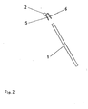
- Die erfinderische Lösung soll anhand eines Ausführungsbeispiels, das in den Fign. 1 und 2 dargestellt ist, näher erläutert werden. Zur besseren Veranschaulichung sind die Figuren als Explosionszeichnungen dargestellt.
- Der Schirm 1 ist in einer aus zwei Schenkeln bestehenden U-förmigen Aufnahme 5 der Aufnahmeleiste 2 angeordnet. Beide Schenkel der U-förmigen Aufnahme 5 der Aufnahmeleiste 2 sind mit Anlaufschrägen zur besseren Einführung des Schirmes 1 bei der Montage versehen. In einer weiteren Ausführungsform ist jedoch auch denkbar, nur einen der Schenkel mit einer Anlaufschräge zu versehen. Der obere Schenkel der U-förmigen Aufnahme 5 der Aufnahmeleiste 2, der an der Oberseite des Schirmes 1 angeordnet ist, ist mit einem Klemmelement 6 versehen. Im Ausführungsbeispiel ist das Klemmelement 6 keilförmig ausgeführt. Es sind jedoch auch andere Ausführungsformen denkbar z.B. ein Klemmelement 6 in Halbkreisform, Kreissegmentform usw. Durch die im Ausführungsbeispiel vorgesehene Befestigung des Schirmes 1 an dessen Oberkante in der Aufnahmeleiste 2 entfällt der optisch störende im Hauptsichtbereich liegende Übergang zwischen Schirm 1 und dem im Stand der Technik üblichen Seitenhalterungen. Der Schirm 1 benötigt nur noch eine gerade Kante, die übrigen Kanten können formschön schräg oder gerundet ausgeführt werden. Im Ausführungsbeispiel wird die Aufnahmeleiste 2 aus einem Aluminium-Strangpress-Teil hergestellt. Dieses Teil lässt sich mit der notwendigen Genauigkeit herstellen und gewährleistet so ein sicheres Klemmen des Schirmes 1. Der Schirm 1 wird in der Aufnahmeleiste 2 ausschließlich durch die Klemmverbindung gehalten. Eine Klebeverbindung ist nicht nötig und auch nicht möglich, da Klebestellen an Dunstabzugshauben vom Fett des Wrasens leicht zerstört werden können. Aluminium ist auch unter den Einsatzbedingungen bei Dunstabzugshauben sehr beständig gegenüber Temperatur, Fett und Alterung. Dadurch wird eine sichere Halterung des Schirmes während seiner gesamten Lebensdauer gewährleistet. Der Schirm 1 im Ausführungsbeispiel wird aus Glas hergestellt. Es sind jedoch auch andere Materialien für andere Ausführungsformen möglich. Die Aufnahmeleiste 2 ist an der Oberkante profiliert, im Ausführungsbeispiel rund, ausgeführt, um eine sichere und einfache Befestigung in einem seitlich anordnenbaren Lager 3 zu ermöglichen. In weiteren Ausführungsformen sind andere Profilierungen, z.B. jede eckige Form der Oberkante der Aufnahmeleiste 2 und der entsprechenden Aufnahme des Lagers 3 möglich.
Claims (4)
- Wrasenleitschirm für eine Dunstabzugshaube, welcher Schirm (1) mit einer Seite in einer Klemmverbindung in einer Aufnahmeleiste (2) angeordnet ist, an der eine aus zwei Schenkeln bestehende U-förmige Aufnahme (5) zur Anordnung des Schirms (1) angeordnet ist, dadurch gekennzeichnet, dass die Schenkel der U-förmigen Aufnahme (5) der Aufnahmeleiste (2) mit Anlaufschrägen zur Einführung des Schirmes (1) versehen sind und an einem der Schenkel, bevorzugt an dem oberen Schenkel ein Klemmelement (6) angeordnet ist.
- Wrasenleitschirm für eine Dunstabzugshaube nach Anspruch 1, dadurch gekennzeichnet, dass die Aufnahmeleiste (2) an der hinteren Seite des Schirms (1) angeordnet ist.
- Wrasenleitschirm für eine Dunstabzugshaube nach den Ansprüchen 1 oder 2, dadurch gekennzeichnet, dass die Aufnahmeleiste (2) aus Aluminium und der Schirm (1) aus Glas bestehen.
- Wrasenleitschirm für eine Dunstabzugshaube nach einem der vorhergehenden Ansprüche, dadurch gekennzeichnet, dass die Aufnahmeleiste (2) mit einem Profilteil in einem Lager (3) mit korrespondierender Aufnahme angeordnet ist, welches in einem Federprofil (4) angeordnet ist, wobei das Federprofil (4) mit einem Rastmechanismus zur Einstellung des Wrasenleitschirms versehen ist oder mit einem Rastmechanismus der Dunstabzugshaube in Wirkverbindung steht.
Applications Claiming Priority (2)
| Application Number | Priority Date | Filing Date | Title |
|---|---|---|---|
| DE20020955U DE20020955U1 (de) | 2000-12-11 | 2000-12-11 | Wrasenleitschirm für eine Dunstabzugshaube |
| DE20020955U | 2000-12-11 |
Publications (2)
| Publication Number | Publication Date |
|---|---|
| EP1217307A1 EP1217307A1 (de) | 2002-06-26 |
| EP1217307B1 true EP1217307B1 (de) | 2006-04-05 |
Family
ID=7949912
Family Applications (1)
| Application Number | Title | Priority Date | Filing Date |
|---|---|---|---|
| EP01127670A Expired - Lifetime EP1217307B1 (de) | 2000-12-11 | 2001-11-20 | Wrasenleitschirm für eine Dunstabzugshaube |
Country Status (3)
| Country | Link |
|---|---|
| EP (1) | EP1217307B1 (de) |
| AT (1) | ATE322651T1 (de) |
| DE (2) | DE20020955U1 (de) |
Family Cites Families (7)
| Publication number | Priority date | Publication date | Assignee | Title |
|---|---|---|---|---|
| DE7012830U (de) | 1969-04-15 | 1970-07-16 | Bergmark Nils R | Kuechenherdhaube, insbesondere fuer eine zentralentlueftungsanlage. |
| AT335677B (de) * | 1974-07-02 | 1977-03-25 | Bosch Siemens Hausgeraete | Luftreinigungsgerat, insbesondere uber kuchenherden od.dgl. anbringbare dunstabzugshaube |
| DE7634851U1 (de) | 1976-11-03 | 1977-10-20 | Georg Roehl Lichttechnische Spezialfabrik Apparate- Und Geraetebau, 8400 Regensburg | Einbau-kuechendunstabzugshaube |
| DE7722123U1 (de) | 1977-07-14 | 1981-07-09 | Bosch-Siemens Hausgeräte GmbH, 7000 Stuttgart | Zwischen anbaueinheiten einer anbaukueche einbaubare dunstabzugshaube o.dgl. |
| FR2418995A7 (fr) * | 1978-03-03 | 1979-09-28 | Scholtes Ets Eugen | Dispositif de support d'un auvent dans une hotte de cuisine |
| DE8801606U1 (de) | 1988-02-09 | 1989-06-08 | Imaro Gmbh, 6072 Dreieich | Haushaltskochstelleneinrichtung |
| IT1262058B (it) * | 1993-02-03 | 1996-06-19 | Valcucine Spa | Cappa di aspirazione per cucine |
-
2000
- 2000-12-11 DE DE20020955U patent/DE20020955U1/de not_active Expired - Lifetime
-
2001
- 2001-11-20 DE DE50109426T patent/DE50109426D1/de not_active Expired - Fee Related
- 2001-11-20 EP EP01127670A patent/EP1217307B1/de not_active Expired - Lifetime
- 2001-11-20 AT AT01127670T patent/ATE322651T1/de not_active IP Right Cessation
Also Published As
| Publication number | Publication date |
|---|---|
| DE50109426D1 (de) | 2006-05-18 |
| ATE322651T1 (de) | 2006-04-15 |
| EP1217307A1 (de) | 2002-06-26 |
| DE20020955U1 (de) | 2001-02-08 |
Similar Documents
| Publication | Publication Date | Title |
|---|---|---|
| DE3713281C2 (de) | ||
| AT506783A4 (de) | Bewegbarer möbelauszug mit relingverstellung | |
| EP2325565A2 (de) | Befestigungselement | |
| DE102004046484B4 (de) | Kastenförmige Bedienblende | |
| AT1969U1 (de) | Wandstütze für fassadenunterkonstruktionen | |
| DE202019103794U1 (de) | Abschlussleiste mit Seitenführung | |
| DE102010003901A1 (de) | Aufhängsicherung für Essen und Hauben | |
| DE4116820C2 (de) | Rahmenleiste zur Verbindung eines Glaskeramikkochfeldes mit einem Bedienteil | |
| EP3369341B1 (de) | Wandelement für eine zarge einer schublade | |
| EP2469189A2 (de) | Dunstabzugshaube mit einer Befestigungsvorrichtung zur Befestigung eines Wrasenschirms und Verfahren zur Befestigung | |
| AT512882B1 (de) | Schubladenrückwand | |
| EP2243650A2 (de) | Blendenanordnung für ein KFZ-Fenster | |
| DE102008013004B4 (de) | Anordnung mit einem Kochfeld und einer Arbeitsplatte | |
| DE3104910C2 (de) | Backofen | |
| DE20020955U1 (de) | Wrasenleitschirm für eine Dunstabzugshaube | |
| DE102017203740B4 (de) | Luftausströmeranordnung | |
| DE29602765U1 (de) | An unterschiedliche Breitenabmessungen anpaßbare Duschabtrennung | |
| DE10153618A1 (de) | Backofentür | |
| DE202010010463U1 (de) | Beleuchtungseinrichtung für einen plattenförmigen Regalboden | |
| DE3421763C2 (de) | ||
| DE102005055438B4 (de) | Kochmulde | |
| EP1705429A3 (de) | Auszugssystem für einen Garofen | |
| DE10038283C2 (de) | Tür, insbesondere für einen Haushaltsofen | |
| DE202019104971U1 (de) | Schubkastenblende | |
| EP3085269B1 (de) | Zarge und möbel-schublade mit vorrichtung zur anbringung einer quer- und/oder längsreling |
Legal Events
| Date | Code | Title | Description |
|---|---|---|---|
| PUAI | Public reference made under article 153(3) epc to a published international application that has entered the european phase |
Free format text: ORIGINAL CODE: 0009012 |
|
| AK | Designated contracting states |
Kind code of ref document: A1 Designated state(s): AT BE CH CY DE DK ES FI FR GB GR IE IT LI LU MC NL PT SE TR |
|
| AX | Request for extension of the european patent |
Free format text: AL;LT;LV;MK;RO;SI |
|
| 17P | Request for examination filed |
Effective date: 20021227 |
|
| AKX | Designation fees paid |
Designated state(s): AT BE CH CY DE DK ES FI FR GB GR IE IT LI LU MC NL PT SE TR |
|
| RAP1 | Party data changed (applicant data changed or rights of an application transferred) |
Owner name: BSH BOSCH UND SIEMENS HAUSGERAETE GMBH |
|
| 17Q | First examination report despatched |
Effective date: 20040129 |
|
| GRAP | Despatch of communication of intention to grant a patent |
Free format text: ORIGINAL CODE: EPIDOSNIGR1 |
|
| GRAS | Grant fee paid |
Free format text: ORIGINAL CODE: EPIDOSNIGR3 |
|
| GRAA | (expected) grant |
Free format text: ORIGINAL CODE: 0009210 |
|
| AK | Designated contracting states |
Kind code of ref document: B1 Designated state(s): AT BE CH CY DE DK ES FI FR GB GR IE IT LI LU MC NL PT SE TR |
|
| PG25 | Lapsed in a contracting state [announced via postgrant information from national office to epo] |
Ref country code: IT Free format text: LAPSE BECAUSE OF FAILURE TO SUBMIT A TRANSLATION OF THE DESCRIPTION OR TO PAY THE FEE WITHIN THE PRESCRIBED TIME-LIMIT;WARNING: LAPSES OF ITALIAN PATENTS WITH EFFECTIVE DATE BEFORE 2007 MAY HAVE OCCURRED AT ANY TIME BEFORE 2007. THE CORRECT EFFECTIVE DATE MAY BE DIFFERENT FROM THE ONE RECORDED. Effective date: 20060405 Ref country code: IE Free format text: LAPSE BECAUSE OF FAILURE TO SUBMIT A TRANSLATION OF THE DESCRIPTION OR TO PAY THE FEE WITHIN THE PRESCRIBED TIME-LIMIT Effective date: 20060405 Ref country code: FI Free format text: LAPSE BECAUSE OF FAILURE TO SUBMIT A TRANSLATION OF THE DESCRIPTION OR TO PAY THE FEE WITHIN THE PRESCRIBED TIME-LIMIT Effective date: 20060405 Ref country code: GB Free format text: LAPSE BECAUSE OF FAILURE TO SUBMIT A TRANSLATION OF THE DESCRIPTION OR TO PAY THE FEE WITHIN THE PRESCRIBED TIME-LIMIT Effective date: 20060405 Ref country code: NL Free format text: LAPSE BECAUSE OF FAILURE TO SUBMIT A TRANSLATION OF THE DESCRIPTION OR TO PAY THE FEE WITHIN THE PRESCRIBED TIME-LIMIT Effective date: 20060405 |
|
| REG | Reference to a national code |
Ref country code: GB Ref legal event code: FG4D Free format text: NOT ENGLISH |
|
| REG | Reference to a national code |
Ref country code: CH Ref legal event code: EP |
|
| REG | Reference to a national code |
Ref country code: IE Ref legal event code: FG4D Free format text: LANGUAGE OF EP DOCUMENT: GERMAN |
|
| REF | Corresponds to: |
Ref document number: 50109426 Country of ref document: DE Date of ref document: 20060518 Kind code of ref document: P |
|
| PG25 | Lapsed in a contracting state [announced via postgrant information from national office to epo] |
Ref country code: SE Free format text: LAPSE BECAUSE OF FAILURE TO SUBMIT A TRANSLATION OF THE DESCRIPTION OR TO PAY THE FEE WITHIN THE PRESCRIBED TIME-LIMIT Effective date: 20060705 Ref country code: DK Free format text: LAPSE BECAUSE OF FAILURE TO SUBMIT A TRANSLATION OF THE DESCRIPTION OR TO PAY THE FEE WITHIN THE PRESCRIBED TIME-LIMIT Effective date: 20060705 |
|
| PG25 | Lapsed in a contracting state [announced via postgrant information from national office to epo] |
Ref country code: ES Free format text: LAPSE BECAUSE OF FAILURE TO SUBMIT A TRANSLATION OF THE DESCRIPTION OR TO PAY THE FEE WITHIN THE PRESCRIBED TIME-LIMIT Effective date: 20060716 |
|
| PG25 | Lapsed in a contracting state [announced via postgrant information from national office to epo] |
Ref country code: PT Free format text: LAPSE BECAUSE OF FAILURE TO SUBMIT A TRANSLATION OF THE DESCRIPTION OR TO PAY THE FEE WITHIN THE PRESCRIBED TIME-LIMIT Effective date: 20060905 |
|
| NLV1 | Nl: lapsed or annulled due to failure to fulfill the requirements of art. 29p and 29m of the patents act | ||
| GBV | Gb: ep patent (uk) treated as always having been void in accordance with gb section 77(7)/1977 [no translation filed] |
Effective date: 20060405 |
|
| REG | Reference to a national code |
Ref country code: IE Ref legal event code: FD4D |
|
| PG25 | Lapsed in a contracting state [announced via postgrant information from national office to epo] |
Ref country code: LI Free format text: LAPSE BECAUSE OF NON-PAYMENT OF DUE FEES Effective date: 20061130 Ref country code: BE Free format text: LAPSE BECAUSE OF NON-PAYMENT OF DUE FEES Effective date: 20061130 Ref country code: MC Free format text: LAPSE BECAUSE OF NON-PAYMENT OF DUE FEES Effective date: 20061130 Ref country code: CH Free format text: LAPSE BECAUSE OF NON-PAYMENT OF DUE FEES Effective date: 20061130 |
|
| PLBE | No opposition filed within time limit |
Free format text: ORIGINAL CODE: 0009261 |
|
| STAA | Information on the status of an ep patent application or granted ep patent |
Free format text: STATUS: NO OPPOSITION FILED WITHIN TIME LIMIT |
|
| 26N | No opposition filed |
Effective date: 20070108 |
|
| EN | Fr: translation not filed | ||
| REG | Reference to a national code |
Ref country code: CH Ref legal event code: PL |
|
| BERE | Be: lapsed |
Owner name: BSH BOSCH UND SIEMENS HAUSGERATE G.M.B.H. Effective date: 20061130 |
|
| PGFP | Annual fee paid to national office [announced via postgrant information from national office to epo] |
Ref country code: DE Payment date: 20071130 Year of fee payment: 7 |
|
| PG25 | Lapsed in a contracting state [announced via postgrant information from national office to epo] |
Ref country code: AT Free format text: LAPSE BECAUSE OF NON-PAYMENT OF DUE FEES Effective date: 20061120 |
|
| PGFP | Annual fee paid to national office [announced via postgrant information from national office to epo] |
Ref country code: IT Payment date: 20071128 Year of fee payment: 7 |
|
| PG25 | Lapsed in a contracting state [announced via postgrant information from national office to epo] |
Ref country code: GR Free format text: LAPSE BECAUSE OF FAILURE TO SUBMIT A TRANSLATION OF THE DESCRIPTION OR TO PAY THE FEE WITHIN THE PRESCRIBED TIME-LIMIT Effective date: 20060706 Ref country code: FR Free format text: LAPSE BECAUSE OF FAILURE TO SUBMIT A TRANSLATION OF THE DESCRIPTION OR TO PAY THE FEE WITHIN THE PRESCRIBED TIME-LIMIT Effective date: 20070309 |
|
| PGFP | Annual fee paid to national office [announced via postgrant information from national office to epo] |
Ref country code: TR Payment date: 20071102 Year of fee payment: 7 |
|
| PG25 | Lapsed in a contracting state [announced via postgrant information from national office to epo] |
Ref country code: LU Free format text: LAPSE BECAUSE OF NON-PAYMENT OF DUE FEES Effective date: 20061120 |
|
| PG25 | Lapsed in a contracting state [announced via postgrant information from national office to epo] |
Ref country code: CY Free format text: LAPSE BECAUSE OF FAILURE TO SUBMIT A TRANSLATION OF THE DESCRIPTION OR TO PAY THE FEE WITHIN THE PRESCRIBED TIME-LIMIT Effective date: 20060405 Ref country code: FR Free format text: LAPSE BECAUSE OF FAILURE TO SUBMIT A TRANSLATION OF THE DESCRIPTION OR TO PAY THE FEE WITHIN THE PRESCRIBED TIME-LIMIT Effective date: 20060405 |
|
| PG25 | Lapsed in a contracting state [announced via postgrant information from national office to epo] |
Ref country code: IT Free format text: LAPSE BECAUSE OF NON-PAYMENT OF DUE FEES Effective date: 20081120 |
|
| PG25 | Lapsed in a contracting state [announced via postgrant information from national office to epo] |
Ref country code: DE Free format text: LAPSE BECAUSE OF NON-PAYMENT OF DUE FEES Effective date: 20090603 |
|
| PG25 | Lapsed in a contracting state [announced via postgrant information from national office to epo] |
Ref country code: TR Free format text: LAPSE BECAUSE OF NON-PAYMENT OF DUE FEES Effective date: 20100928 |
|
| PG25 | Lapsed in a contracting state [announced via postgrant information from national office to epo] |
Ref country code: TR Free format text: LAPSE BECAUSE OF NON-PAYMENT OF DUE FEES Effective date: 20081120 |