EP1217215A2 - Gas compressor - Google Patents
Gas compressor Download PDFInfo
- Publication number
- EP1217215A2 EP1217215A2 EP01310845A EP01310845A EP1217215A2 EP 1217215 A2 EP1217215 A2 EP 1217215A2 EP 01310845 A EP01310845 A EP 01310845A EP 01310845 A EP01310845 A EP 01310845A EP 1217215 A2 EP1217215 A2 EP 1217215A2
- Authority
- EP
- European Patent Office
- Prior art keywords
- discharge
- oil
- gas
- cylinder
- refrigerant gas
- Prior art date
- Legal status (The legal status is an assumption and is not a legal conclusion. Google has not performed a legal analysis and makes no representation as to the accuracy of the status listed.)
- Granted
Links
Images

Classifications
-
- F—MECHANICAL ENGINEERING; LIGHTING; HEATING; WEAPONS; BLASTING
- F04—POSITIVE - DISPLACEMENT MACHINES FOR LIQUIDS; PUMPS FOR LIQUIDS OR ELASTIC FLUIDS
- F04C—ROTARY-PISTON, OR OSCILLATING-PISTON, POSITIVE-DISPLACEMENT MACHINES FOR LIQUIDS; ROTARY-PISTON, OR OSCILLATING-PISTON, POSITIVE-DISPLACEMENT PUMPS
- F04C29/00—Component parts, details or accessories of pumps or pumping installations, not provided for in groups F04C18/00 - F04C28/00
- F04C29/12—Arrangements for admission or discharge of the working fluid, e.g. constructional features of the inlet or outlet
-
- F—MECHANICAL ENGINEERING; LIGHTING; HEATING; WEAPONS; BLASTING
- F04—POSITIVE - DISPLACEMENT MACHINES FOR LIQUIDS; PUMPS FOR LIQUIDS OR ELASTIC FLUIDS
- F04C—ROTARY-PISTON, OR OSCILLATING-PISTON, POSITIVE-DISPLACEMENT MACHINES FOR LIQUIDS; ROTARY-PISTON, OR OSCILLATING-PISTON, POSITIVE-DISPLACEMENT PUMPS
- F04C18/00—Rotary-piston pumps specially adapted for elastic fluids
- F04C18/30—Rotary-piston pumps specially adapted for elastic fluids having the characteristics covered by two or more of groups F04C18/02, F04C18/08, F04C18/22, F04C18/24, F04C18/48, or having the characteristics covered by one of these groups together with some other type of movement between co-operating members
- F04C18/34—Rotary-piston pumps specially adapted for elastic fluids having the characteristics covered by two or more of groups F04C18/02, F04C18/08, F04C18/22, F04C18/24, F04C18/48, or having the characteristics covered by one of these groups together with some other type of movement between co-operating members having the movement defined in group F04C18/08 or F04C18/22 and relative reciprocation between the co-operating members
- F04C18/344—Rotary-piston pumps specially adapted for elastic fluids having the characteristics covered by two or more of groups F04C18/02, F04C18/08, F04C18/22, F04C18/24, F04C18/48, or having the characteristics covered by one of these groups together with some other type of movement between co-operating members having the movement defined in group F04C18/08 or F04C18/22 and relative reciprocation between the co-operating members with vanes reciprocating with respect to the inner member
- F04C18/3446—Rotary-piston pumps specially adapted for elastic fluids having the characteristics covered by two or more of groups F04C18/02, F04C18/08, F04C18/22, F04C18/24, F04C18/48, or having the characteristics covered by one of these groups together with some other type of movement between co-operating members having the movement defined in group F04C18/08 or F04C18/22 and relative reciprocation between the co-operating members with vanes reciprocating with respect to the inner member the inner and outer member being in contact along more than one line or surface
-
- F—MECHANICAL ENGINEERING; LIGHTING; HEATING; WEAPONS; BLASTING
- F04—POSITIVE - DISPLACEMENT MACHINES FOR LIQUIDS; PUMPS FOR LIQUIDS OR ELASTIC FLUIDS
- F04C—ROTARY-PISTON, OR OSCILLATING-PISTON, POSITIVE-DISPLACEMENT MACHINES FOR LIQUIDS; ROTARY-PISTON, OR OSCILLATING-PISTON, POSITIVE-DISPLACEMENT PUMPS
- F04C29/00—Component parts, details or accessories of pumps or pumping installations, not provided for in groups F04C18/00 - F04C28/00
- F04C29/02—Lubrication; Lubricant separation
- F04C29/026—Lubricant separation
-
- F—MECHANICAL ENGINEERING; LIGHTING; HEATING; WEAPONS; BLASTING
- F04—POSITIVE - DISPLACEMENT MACHINES FOR LIQUIDS; PUMPS FOR LIQUIDS OR ELASTIC FLUIDS
- F04C—ROTARY-PISTON, OR OSCILLATING-PISTON, POSITIVE-DISPLACEMENT MACHINES FOR LIQUIDS; ROTARY-PISTON, OR OSCILLATING-PISTON, POSITIVE-DISPLACEMENT PUMPS
- F04C2250/00—Geometry
- F04C2250/10—Geometry of the inlet or outlet
Definitions
- the present invention relates to a gas compressor mounted in a vehicle as a part of an automotive air conditioner system or mounted in an exterior unit as a part of an air conditioning system and, in particular, to a gas compressor in which the pressure loss of an oil containing high-pressure refrigerant gas is reduced to thereby achieve an improvement in compressor performance.
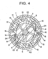
- an example of a gas compressor of this type has a cylinder 1 having a substantially elliptical inner peripheral configuration, side blocks 2 and 3 being respectively mounted to the end surfaces of the cylinder 1.
- a rotor 4 is arranged inside the cylinder 1 between the front and rear side blocks 2 and 3.
- the rotor 4 is horizontally positioned so as to be rotatable through a rotor shaft 5 integrally provided at its axial center and bearings 6 and 7 of the side blocks 2 and 3 supporting the same.
- vanes 9 are respectively attached to these vane grooves 8, the vanes 9 being capable of jutting out from the outer peripheral surface of the rotor 4 toward the inner wall of the cylinder 1 and retracting into the rotor 4.
- the interior of the cylinder 1 is divided into a plurality of small chambers by the inner wall of the cylinder 1, the inner surfaces of the side blocks 2 and 3, the outer peripheral surface of the rotor 4, and the side surfaces of the forward end portions of the vanes 9.
- the small chambers thus defined constitute compression chambers 10, whose volume is repeatedly varied as the rotor.4 rotates in the direction of the arrow RD.
- the oil containing low-pressure refrigerant gas in a suction chamber 11 is introduced into the compression chambers 10 through suction passages 12 of the cylinder 1 and inlets 13 of the side blocks 2 and 3. Then, when the volume of the compression chambers 10 starts to decrease, the refrigerant gas in the compress ion chambers 10 starts to be compressed due to the volume reduction effect. Thereafter, when the volume of the compression chambers 10 approaches to its minimum, discharge valves 15 of cylinder discharge holes 14 provided near the elliptically short diameter portion of the cylinder 1 are opened by the pressure of the compressed oil containing high-pressure refrigerant gas. As a result, the oil containing high-pressure refrigerant gas in the compression chambers 10 are discharged through the cylinder discharge holes 14.
- the oil containing high-pressure refrigerant gas discharged through the cylinder discharge holes 14 flows through discharge chambers 16 and discharge gas passages 24 in the outer periphery of the cylinder 1 before it is led to oil separation filters 18-1 of an oil separator 18 mounted to the rear portion of the side block 3.
- the oil containing high-pressure refrigerant gas led to the oil separation filters 18-1 is separated into an oil component and a gas component as a result, for example, of striking against wire-meshes constituting the oil separation filters 18-1.
- the gas component flows into a discharge chamber 19, and is then supplied from the discharge chamber 19 to the condenser side of the air conditioning system by way of a discharge port of a compressor case (not shown).
- the oil component drips down into an oil sump 20 at the bottom of the discharge chamber 19 to be stored, and is supplied to portions where oil is required through an oil passage 21 of the side blocks 2 and 3 and the cylinder 1.
- Examples of the portions where the oil is required include the clearances of the bearings 6 and 7, flat grooves 22 formed on the sides of the side blocks 2 and 3 facing the cylinder, and vane back pressure spaces 23 at the bottom of the vanes 9 communicating therewith.
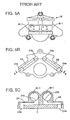
- the above-described conventional gas compressor adopts a structure in which, to enhance the oil separation performance, the discharge gas passages 24 of the oil separator 18 are bent twice at right angles to thereby cause the oil containing high-pressure refrigerant gas to strike against the inner walls of the gas passages 24 twice.
- This striking construction provides little or no effect of improving the oil separation performance. Rather, it involves an increase in the pressure loss of the oil containing high-pressure refrigerant gas, which leads to deterioration in the compressor performance.
- the present invention has been made with a view toward solving the above problem in the prior art. It is an object of the present invention to provide a gas compressor which can reduce the pressure loss of the oil containing high-pressure refrigerant gas to thereby achieve an improvement in compressor performance.
- the present invention relates to a gas compressor comprising a cylinder arranged between a pair of side blocks, a rotor horizontally arranged in the cylinder so as to be rotatable, vanes provided so as to be capable of jutting out toward the inner wall of the cylinder from the outer peripheral surface of the rotor and retracting therein, compression chambers defined by the cylinder, the side blocks, the rotor, and the vanes, cylinder discharge holes for discharging refrigerant gas from the compression chambers, a discharge chamber for temporarily storing the refrigerant gas discharged from the cylinder discharge holes, a linear discharge gas passage for guiding the refrigerant gas from the discharge chamber to the downstream side of the discharge chamber, an oil separator arranged on the downstream side of the discharge gas passage and having an oil separation filter for separating the refrigerant gas and the oil from each other, and a discharge chamber for temporarily storing the refrigerant gas and the oil separated by the oil separation filter.
- the discharge gas passage is made linear, whereby the oil containing high-pressure refrigerant gas flows smoothly through the discharge gas passage, thereby reducing the pressure loss of the oil containing high-pressure refrigerant gas.
- present invention relates to a gas compressor, wherein the height of an outlet opening on the oil separator side of the discharge gas passage is set to be the same as the height of an inlet opening of the discharge gas passage, whereby the discharge gas passage extends horizontally.
- the oil separator side opening of the discharge gas passage communicating with the discharge chamber is set to be of the same height as the inlet opening thereof, whereby the discharge gas passage extends horizontally and is of the shortest length, whereby it is possible to further reduce the pressure loss of the oil containing high-pressure refrigerant gas.
- the present invention relates to a gas compressor, wherein the oil separation filter of the oil separator is positioned above the outlet opening of the discharge gas passage.
- the oil separation filter of the oil separator is positioned above the outlet opening of the discharge gas passage, so that a large space can be secured for the oil sump below the oil separation filter.
- the basic construction of the gas compressor of this embodiment is the same as that of the gas compressor shown in Figs. 3 and 4, in which the cylinder 1 is arranged between a pair of side blocks 2 and 3 and in which the rotor 4 is horizontally arranged inside the cylinder 1 so as to be rotatable, the vanes 9 being provided so as to be capable of jutting out toward the inner wall of the cylinder 1 from the outer peripheral surface of the rotor 4 and retracting therein.
- the compression chambers 10 defined by the vanes 9, etc. are provided, and the volume of the compression chambers 10 repeatedly increases and decreases as the rotor 4 rotates, whereby the oil containing low-pressure refrigerant gas in the suction chamber is taken in and compressed.
- the compressed oil containing high-pressure refrigerant gas is discharged through the cylinder discharge holes 14 as previously described.
- the component which are the same as those of the described gas compressor will be indicated by the same reference numerals, and a detailed description of such components will be omitted.
- the oil containing high-pressure refrigerant gas discharged through the cylinder discharge holes 14 as described above flows through the discharge chamber 16 and the discharge gas passages 24 and is led to the oil separation filters 18-1 attached to the oil separator 18.
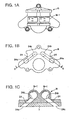
- the discharge gas passages 24 are formed into a linear shape so as to realize linearization thereof.
- each discharge gas passage 24 opens on the discharge chamber 16 side, and the other end 24b thereof opens on the oil separation filter 18-1 side of the oil separation filter 18.
- the section between one end (inlet opening) 24a of each discharge gas passage 24 and the other end (outlet opening) 24b thereof extends in a completely straight line, without being bent anywhere.
- the discharge gas passage 24 is formed linear whichever direction from seen, for example, front or rear view shown in Fig. 1B, plane view like shown in Fig. 1C, and side view like shown in Fig. 3.
- Each discharge gas passage 24 is formed extending from the discharge chambers 16 to the oil separator 18 through the rear side block 3 in a punching manner. In this embodiment, the angle at which the discharge gas passage 24 reaches the oil separator 18 is not also changed.
- each discharge gas passage 24 in the conventional gas compressor is bent substantially at right angles immediately after entering the oil separator 18 through the rear side block 3, whereas, as shown in Fig. 1, each discharge gas passage 24 of the gas compressor of this embodiment is not bent immediately after entering the oil separator 18 through the rear side block 3, and is formed linear.
- cylinder discharge holes 14, two discharge chambers 16, two discharge gas passages 24, and two oil separation filters 18-1 of the oil separator 18 are provided. This is due to the substantially elliptical inner peripheral configuration of the cylinder 1 and due to the structure in which five vanes 9 are provided.
- intake operation and compressing operation are executed at two positions in the cylinder 1, and the portions of the oil containing high-pressure refrigerant gas respectively compressed at the two positions are separately guided to the oil separator 18.
- the two discharge gas passages 24 and 24 are both linear. However, they are not parallel to each other but are in a V-shaped arrangement in which they are directed toward the two oil separation filters 18-1 and 18-1 arranged side by side at the center of the oil separator 18.
- the oil containing high-pressure refrigerant gas discharged through the cylinder discharge holes 14 is led to the oil separation filters 18-1 of the oil separator 18 through the discharge chambers 16 and the discharge gas passages 24.
- the discharge gas passages 24 are attempted to be linear, the oil containing high-pressure refrigerant gas can be smoothly transferred from the cylinder discharge holes 14 to the oil separation filters 18-1, whereby the pressure loss of the oil containing high-pressure refrigerant gas is reduced, and the compressor performance is improved.
- the pressure loss of the oil containing high-pressure refrigerant gas also depends on the sectional area of the discharge gas passages 24; the larger the sectional area of the discharge gas passages 24, the less the pressure loss of the oil containing high-pressure refrigerant gas.
- the sectional area of the discharge gas passages 24 be set to be as large as possible.
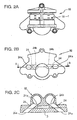
- Fig. 2 shows a configuration of a gas compressor in accordance with another embodiment of the present invention.
- Fig. 2A is a rear elevational view of an oil separator as seen from the rear side
- Fig. 2B is an elevational view of the oil separator as seen from the side abutting the rear side block
- Fig. 2C is a sectional view taken along the line B-B of Fig. 2B.
- the height of one end 24a of each discharge gas passage 24, that is, the height of the discharge chamber 16 side inlet opening constituting the inlet of the discharge gas passage 24, is set to be the same as the height of the other end 24b of the discharge gas passage 24, that is, the height of the oil separator 18 side outlet opening, whereby each discharge gas passage 24 connecting the inlet and outlet openings 24a and 24b extends horizontally and is of the shortest length.
- the discharge gas passages 24 are of the shortest length, it is possible to restrain at a low level the pressure loss of the oil containing high-pressure refrigerant gas, which is discharged from the cylinder discharge holes 14 and led from the discharge chambers 16 to the oil separation filters 18-1 of the oil separator 18 through the discharge gas passages 24.
- discharge gas passages 24 extend horizontally, it is possible to minimize the resistance when passing the high-pressure refrigerant gas therethrough, which also leads to a reduction in pressure loss, thereby achieving a further improvement in compressor function.
- the discharge gas passages are linear, so that the oil containing high-pressure refrigerant gas flows smoothly from the cylinder discharge holes to the oil separation filters of the oil separator through the discharge gas passages, whereby the pressure loss of the oil containing high-pressure refrigerant gas of this type is reduced, thereby achieving an improvement in compressor performance.
- the discharge gas passages are formed linearly, and the height of the inlet opening communicating with the discharge chamber is set to be the same as the height of the outlet opening on the oil separator side, whereby the discharge gas passages extend horizontally and are of the shortest length, thereby further reducing the pressure loss of the oil containing high-pressure refrigerant gas passing through the discharge gas passages to thereby achieve a further improvement in compressor performance.
Landscapes
- Engineering & Computer Science (AREA)
- Mechanical Engineering (AREA)
- General Engineering & Computer Science (AREA)
- Applications Or Details Of Rotary Compressors (AREA)
- Rotary Pumps (AREA)
Abstract
Description
Claims (3)
- A gas compressor comprising:a cylinder arranged between a pair of side blocks;a rotor horizontally arranged in the cylinder so as to be rotatable;vanes provided so as to be capable of jutting out toward the inner wall of the cylinder from the outer peripheral surface of the rotor and retracting therein;compression chambers defined by the cylinder, side blocks, rotor, and vanes;cylinder discharge holes for discharging refrigerant gas from the compression chambers;a discharge chamber for temporarily storing the refrigerant gas discharged from the cylinder discharge holes;a linear discharge gas passage for guiding the refrigerant gas from the discharge chamber to the downstream side of the discharge chamber;an oil separator arranged on the downstream side of the discharge gas passage and having an oil separation filter for separating the refrigerant gas and the oil from each other; anda discharge chamber for temporarily storing the refrigerant gas and the oil separated by the oil separation filter.
- A gas compressor according to claim 1, wherein the height of an outlet opening on the oil separator side of the discharge gas passage is set to be the same as the height of an inlet opening of the discharge gas passage, whereby the discharge gas passage extends horizontally.
- A gas compressor according to claim 2, wherein the oil separation filter of the oil separator is positioned above the outlet opening of the discharge gas passage.
Applications Claiming Priority (4)
| Application Number | Priority Date | Filing Date | Title |
|---|---|---|---|
| JP2000391184 | 2000-12-22 | ||
| JP2000391184 | 2000-12-22 | ||
| JP2001267792A JP3987697B2 (en) | 2000-12-22 | 2001-09-04 | Gas compressor |
| JP2001267792 | 2001-09-04 |
Publications (3)
| Publication Number | Publication Date |
|---|---|
| EP1217215A2 true EP1217215A2 (en) | 2002-06-26 |
| EP1217215A3 EP1217215A3 (en) | 2003-02-26 |
| EP1217215B1 EP1217215B1 (en) | 2005-03-02 |
Family
ID=26606426
Family Applications (1)
| Application Number | Title | Priority Date | Filing Date |
|---|---|---|---|
| EP01310845A Expired - Lifetime EP1217215B1 (en) | 2000-12-22 | 2001-12-21 | Gas compressor |
Country Status (6)
| Country | Link |
|---|---|
| US (1) | US20020094294A1 (en) |
| EP (1) | EP1217215B1 (en) |
| JP (1) | JP3987697B2 (en) |
| CN (1) | CN1309960C (en) |
| DE (1) | DE60109121T2 (en) |
| MY (1) | MY129076A (en) |
Cited By (1)
| Publication number | Priority date | Publication date | Assignee | Title |
|---|---|---|---|---|
| EP3051136A1 (en) * | 2015-01-29 | 2016-08-03 | Pfeiffer Vacuum Gmbh | Vacuum pump |
Families Citing this family (3)
| Publication number | Priority date | Publication date | Assignee | Title |
|---|---|---|---|---|
| US7520210B2 (en) | 2006-09-27 | 2009-04-21 | Visteon Global Technologies, Inc. | Oil separator for a fluid displacement apparatus |
| JP5216470B2 (en) * | 2008-08-08 | 2013-06-19 | カヤバ工業株式会社 | Variable displacement vane pump |
| KR102141871B1 (en) * | 2015-05-26 | 2020-08-07 | 한온시스템 주식회사 | Compressor with an oil return means |
Family Cites Families (10)
| Publication number | Priority date | Publication date | Assignee | Title |
|---|---|---|---|---|
| JPS572704Y2 (en) * | 1978-07-29 | 1982-01-18 | ||
| JPS6016794Y2 (en) * | 1978-08-19 | 1985-05-24 | 株式会社ボッシュオートモーティブ システム | vane compressor |
| JPS57148097A (en) * | 1981-03-09 | 1982-09-13 | Mitsubishi Heavy Ind Ltd | Rotary compressor |
| US4810177A (en) * | 1982-06-18 | 1989-03-07 | Diesel Kiki Co., Ltd. | Vane compressor with vane back pressure adjustment |
| JP2585380Y2 (en) * | 1992-11-20 | 1998-11-18 | カルソニック株式会社 | Rotary compressor |
| JPH0712072A (en) * | 1993-06-23 | 1995-01-17 | Toyota Autom Loom Works Ltd | Vane compressor |
| JPH07151083A (en) * | 1993-11-29 | 1995-06-13 | Nippondenso Co Ltd | Vane compressor |
| JP2913155B2 (en) * | 1995-09-01 | 1999-06-28 | セイコー精機株式会社 | Gas compressor |
| JPH0979156A (en) * | 1995-09-08 | 1997-03-25 | Seiko Seiki Co Ltd | Gas compressor |
| JP2000297773A (en) * | 1999-04-14 | 2000-10-24 | Bosch Automotive Systems Corp | Compressor |
-
2001
- 2001-09-04 JP JP2001267792A patent/JP3987697B2/en not_active Expired - Fee Related
- 2001-12-20 US US10/033,853 patent/US20020094294A1/en not_active Abandoned
- 2001-12-21 EP EP01310845A patent/EP1217215B1/en not_active Expired - Lifetime
- 2001-12-21 DE DE60109121T patent/DE60109121T2/en not_active Expired - Fee Related
- 2001-12-21 MY MYPI20015848A patent/MY129076A/en unknown
- 2001-12-22 CN CNB011381841A patent/CN1309960C/en not_active Expired - Fee Related
Cited By (1)
| Publication number | Priority date | Publication date | Assignee | Title |
|---|---|---|---|---|
| EP3051136A1 (en) * | 2015-01-29 | 2016-08-03 | Pfeiffer Vacuum Gmbh | Vacuum pump |
Also Published As
| Publication number | Publication date |
|---|---|
| DE60109121T2 (en) | 2005-07-21 |
| EP1217215B1 (en) | 2005-03-02 |
| CN1309960C (en) | 2007-04-11 |
| MY129076A (en) | 2007-03-30 |
| DE60109121D1 (en) | 2005-04-07 |
| JP3987697B2 (en) | 2007-10-10 |
| JP2002250289A (en) | 2002-09-06 |
| US20020094294A1 (en) | 2002-07-18 |
| EP1217215A3 (en) | 2003-02-26 |
| CN1362583A (en) | 2002-08-07 |
Similar Documents
| Publication | Publication Date | Title |
|---|---|---|
| KR0133251B1 (en) | Vane compressor | |
| KR102196191B1 (en) | Positive-displacement machine according to the spiral principle, method for operating a positive-displacement machine, positive-displacement spiral, vehicle air-conditioning system and vehicle | |
| US7431571B2 (en) | Noise reduction muffler for hermetic rotary compressor | |
| JP2010031759A (en) | Vane compressor | |
| KR101850785B1 (en) | Compressor | |
| CN100507276C (en) | Compressor | |
| US20050106041A1 (en) | Compressor | |
| JP2003013858A (en) | Compressor | |
| JPH0151913B2 (en) | ||
| EP1217215B1 (en) | Gas compressor | |
| CN115126696A (en) | Compressor rotor, compressor pump body, compressor and temperature regulation system | |
| KR100203755B1 (en) | Vane compressor | |
| CN216922510U (en) | Horizontal scroll compressor | |
| US6872065B1 (en) | Vane gas compressor having two discharge passages with the same length | |
| CN115126697A (en) | Compressor pump body, compressor and temperature regulation system | |
| KR102738349B1 (en) | Electric compressor | |
| JP2005054745A (en) | Compressor | |
| JPH0710484U (en) | Gas compressor | |
| EP0761973A2 (en) | Gas compressor | |
| JP2002266781A (en) | Vane type compressor | |
| JP5843729B2 (en) | Gas compressor | |
| JP3819247B2 (en) | Gas compressor | |
| JPH09317671A (en) | Gas compressor | |
| JPH0643514Y2 (en) | Vane compressor | |
| JP2002242835A (en) | Gas compressor |
Legal Events
| Date | Code | Title | Description |
|---|---|---|---|
| PUAI | Public reference made under article 153(3) epc to a published international application that has entered the european phase |
Free format text: ORIGINAL CODE: 0009012 |
|
| AK | Designated contracting states |
Kind code of ref document: A2 Designated state(s): AT BE CH CY DE DK ES FI FR GB GR IE IT LI LU MC NL PT SE TR |
|
| AX | Request for extension of the european patent |
Free format text: AL;LT;LV;MK;RO;SI |
|
| PUAL | Search report despatched |
Free format text: ORIGINAL CODE: 0009013 |
|
| AK | Designated contracting states |
Designated state(s): AT BE CH CY DE DK ES FI FR GB GR IE IT LI LU MC NL PT SE TR Kind code of ref document: A3 Designated state(s): AT BE CH CY DE DK ES FI FR GB GR IE IT LI LU MC NL PT SE TR |
|
| AX | Request for extension of the european patent |
Extension state: AL LT LV MK RO SI |
|
| 17P | Request for examination filed |
Effective date: 20030819 |
|
| AKX | Designation fees paid |
Designated state(s): DE FR GB |
|
| 17Q | First examination report despatched |
Effective date: 20040112 |
|
| GRAP | Despatch of communication of intention to grant a patent |
Free format text: ORIGINAL CODE: EPIDOSNIGR1 |
|
| RAP1 | Party data changed (applicant data changed or rights of an application transferred) |
Owner name: CALSONIC COMPRESSOR MANUFACTURING INC. |
|
| GRAS | Grant fee paid |
Free format text: ORIGINAL CODE: EPIDOSNIGR3 |
|
| GRAA | (expected) grant |
Free format text: ORIGINAL CODE: 0009210 |
|
| AK | Designated contracting states |
Kind code of ref document: B1 Designated state(s): DE FR GB |
|
| REG | Reference to a national code |
Ref country code: GB Ref legal event code: FG4D |
|
| REG | Reference to a national code |
Ref country code: IE Ref legal event code: FG4D |
|
| REF | Corresponds to: |
Ref document number: 60109121 Country of ref document: DE Date of ref document: 20050407 Kind code of ref document: P |
|
| ET | Fr: translation filed | ||
| PLBE | No opposition filed within time limit |
Free format text: ORIGINAL CODE: 0009261 |
|
| STAA | Information on the status of an ep patent application or granted ep patent |
Free format text: STATUS: NO OPPOSITION FILED WITHIN TIME LIMIT |
|
| 26N | No opposition filed |
Effective date: 20051205 |
|
| PGFP | Annual fee paid to national office [announced via postgrant information from national office to epo] |
Ref country code: FR Payment date: 20081212 Year of fee payment: 8 |
|
| PGFP | Annual fee paid to national office [announced via postgrant information from national office to epo] |
Ref country code: DE Payment date: 20081219 Year of fee payment: 8 |
|
| PGFP | Annual fee paid to national office [announced via postgrant information from national office to epo] |
Ref country code: GB Payment date: 20081217 Year of fee payment: 8 |
|
| GBPC | Gb: european patent ceased through non-payment of renewal fee |
Effective date: 20091221 |
|
| REG | Reference to a national code |
Ref country code: FR Ref legal event code: ST Effective date: 20100831 |
|
| PG25 | Lapsed in a contracting state [announced via postgrant information from national office to epo] |
Ref country code: FR Free format text: LAPSE BECAUSE OF NON-PAYMENT OF DUE FEES Effective date: 20091231 |
|
| PG25 | Lapsed in a contracting state [announced via postgrant information from national office to epo] |
Ref country code: DE Free format text: LAPSE BECAUSE OF NON-PAYMENT OF DUE FEES Effective date: 20100701 |
|
| PG25 | Lapsed in a contracting state [announced via postgrant information from national office to epo] |
Ref country code: GB Free format text: LAPSE BECAUSE OF NON-PAYMENT OF DUE FEES Effective date: 20091221 |