EP1216911A2 - Steering control for self-propelled vehicles - Google Patents
Steering control for self-propelled vehicles Download PDFInfo
- Publication number
- EP1216911A2 EP1216911A2 EP01811178A EP01811178A EP1216911A2 EP 1216911 A2 EP1216911 A2 EP 1216911A2 EP 01811178 A EP01811178 A EP 01811178A EP 01811178 A EP01811178 A EP 01811178A EP 1216911 A2 EP1216911 A2 EP 1216911A2
- Authority
- EP
- European Patent Office
- Prior art keywords
- steering
- gripping zone
- piloting device
- sensor
- piloting
- Prior art date
- Legal status (The legal status is an assumption and is not a legal conclusion. Google has not performed a legal analysis and makes no representation as to the accuracy of the status listed.)
- Withdrawn
Links
- 230000008859 change Effects 0.000 claims abstract description 6
- 238000006243 chemical reaction Methods 0.000 claims description 8
- 239000012530 fluid Substances 0.000 claims description 8
- 239000000463 material Substances 0.000 claims description 7
- 229920002635 polyurethane Polymers 0.000 claims description 3
- 239000004814 polyurethane Substances 0.000 claims description 3
- 238000009434 installation Methods 0.000 claims description 2
- 241000380131 Ammophila arenaria Species 0.000 abstract description 4
- 230000008901 benefit Effects 0.000 description 11
- 230000035484 reaction time Effects 0.000 description 7
- 230000036632 reaction speed Effects 0.000 description 4
- 230000001105 regulatory effect Effects 0.000 description 4
- 230000001276 controlling effect Effects 0.000 description 3
- 230000011664 signaling Effects 0.000 description 3
- 230000009471 action Effects 0.000 description 2
- 230000003213 activating effect Effects 0.000 description 2
- 230000004913 activation Effects 0.000 description 2
- 230000000981 bystander Effects 0.000 description 2
- 230000000694 effects Effects 0.000 description 2
- 229910000831 Steel Inorganic materials 0.000 description 1
- 238000005299 abrasion Methods 0.000 description 1
- 230000006978 adaptation Effects 0.000 description 1
- 230000005540 biological transmission Effects 0.000 description 1
- 238000011109 contamination Methods 0.000 description 1
- 230000010485 coping Effects 0.000 description 1
- 239000000428 dust Substances 0.000 description 1
- 229920001971 elastomer Polymers 0.000 description 1
- 239000000806 elastomer Substances 0.000 description 1
- 230000008030 elimination Effects 0.000 description 1
- 238000003379 elimination reaction Methods 0.000 description 1
- 239000007788 liquid Substances 0.000 description 1
- 230000003287 optical effect Effects 0.000 description 1
- 210000000056 organ Anatomy 0.000 description 1
- 239000010959 steel Substances 0.000 description 1
- 230000000007 visual effect Effects 0.000 description 1
Images


Classifications
-
- B—PERFORMING OPERATIONS; TRANSPORTING
- B62—LAND VEHICLES FOR TRAVELLING OTHERWISE THAN ON RAILS
- B62D—MOTOR VEHICLES; TRAILERS
- B62D1/00—Steering controls, i.e. means for initiating a change of direction of the vehicle
- B62D1/02—Steering controls, i.e. means for initiating a change of direction of the vehicle vehicle-mounted
- B62D1/04—Hand wheels
- B62D1/06—Rims, e.g. with heating means; Rim covers
-
- B—PERFORMING OPERATIONS; TRANSPORTING
- B60—VEHICLES IN GENERAL
- B60Q—ARRANGEMENT OF SIGNALLING OR LIGHTING DEVICES, THE MOUNTING OR SUPPORTING THEREOF OR CIRCUITS THEREFOR, FOR VEHICLES IN GENERAL
- B60Q1/00—Arrangement of optical signalling or lighting devices, the mounting or supporting thereof or circuits therefor
- B60Q1/0076—Switches therefor
- B60Q1/0082—Switches therefor mounted on the steering wheel
-
- B—PERFORMING OPERATIONS; TRANSPORTING
- B62—LAND VEHICLES FOR TRAVELLING OTHERWISE THAN ON RAILS
- B62J—CYCLE SADDLES OR SEATS; AUXILIARY DEVICES OR ACCESSORIES SPECIALLY ADAPTED TO CYCLES AND NOT OTHERWISE PROVIDED FOR, e.g. ARTICLE CARRIERS OR CYCLE PROTECTORS
- B62J45/00—Electrical equipment arrangements specially adapted for use as accessories on cycles, not otherwise provided for
- B62J45/40—Sensor arrangements; Mounting thereof
-
- B—PERFORMING OPERATIONS; TRANSPORTING
- B62—LAND VEHICLES FOR TRAVELLING OTHERWISE THAN ON RAILS
- B62K—CYCLES; CYCLE FRAMES; CYCLE STEERING DEVICES; RIDER-OPERATED TERMINAL CONTROLS SPECIALLY ADAPTED FOR CYCLES; CYCLE AXLE SUSPENSIONS; CYCLE SIDE-CARS, FORECARS, OR THE LIKE
- B62K11/00—Motorcycles, engine-assisted cycles or motor scooters with one or two wheels
- B62K11/14—Handlebar constructions, or arrangements of controls thereon, specially adapted thereto
-
- B—PERFORMING OPERATIONS; TRANSPORTING
- B62—LAND VEHICLES FOR TRAVELLING OTHERWISE THAN ON RAILS
- B62K—CYCLES; CYCLE FRAMES; CYCLE STEERING DEVICES; RIDER-OPERATED TERMINAL CONTROLS SPECIALLY ADAPTED FOR CYCLES; CYCLE AXLE SUSPENSIONS; CYCLE SIDE-CARS, FORECARS, OR THE LIKE
- B62K21/00—Steering devices
- B62K21/26—Handlebar grips
-
- B—PERFORMING OPERATIONS; TRANSPORTING
- B62—LAND VEHICLES FOR TRAVELLING OTHERWISE THAN ON RAILS
- B62K—CYCLES; CYCLE FRAMES; CYCLE STEERING DEVICES; RIDER-OPERATED TERMINAL CONTROLS SPECIALLY ADAPTED FOR CYCLES; CYCLE AXLE SUSPENSIONS; CYCLE SIDE-CARS, FORECARS, OR THE LIKE
- B62K23/00—Rider-operated controls specially adapted for cycles, i.e. means for initiating control operations, e.g. levers, grips
- B62K23/02—Rider-operated controls specially adapted for cycles, i.e. means for initiating control operations, e.g. levers, grips hand actuated
Definitions
- the present invention concerns a control apparatus for self-propelled vehicles such as motorcycles, automobiles, aircraft, etc.
- All these vehicles are equipped with a steering or piloting control device comprising a steering wheel as in automobiles, handlebars as on motorbikes, control columns (joystick) as in aircraft, a helm as in nautical vehicles, which for steering the vehicle is handled by at least one hand of the pilot (and in many cases by both hands) for effecting the steering or piloting operations.
- a steering or piloting control device comprising a steering wheel as in automobiles, handlebars as on motorbikes, control columns (joystick) as in aircraft, a helm as in nautical vehicles, which for steering the vehicle is handled by at least one hand of the pilot (and in many cases by both hands) for effecting the steering or piloting operations.
- the gripping zone of the steering device serves exclusively for gripping said device and thus to subject it to a determined rotation or translation movement, which effects a change in the course of the vehicle.
- the other command and/or control devices of the vehicle normally consist of switches activated using separate push buttons or levers, which for operation require release of the hand from the gripping zone of the steering device.
- a classic case is the horn of an automobile arranged at the centre of the steering wheel, or of a motorcycle mounted on the handlebars on the left hand side outside the gripping handle. For sounding the horn the driver must move his hand or at least one finger from the gripping position on the steering device in order to press the corresponding button.
- a vehicle steering wheel module is known the diameter of which can be regulated.
- the diameter of the steering wheel can be regulated using two "handles” permitting adaptation of the width at which the driver wants to place his hands.
- This steering wheel is of the fixed type as the direction of the course of the vehicle is regulated by the position of the handles, which can be moved sidewise to and fro.
- the objective of the present invention is to propose a solution to the basic problem of safety of driving a self-propelled vehicle under extreme driving conditions, i.e. where the reaction time of the driver, in the order of milliseconds, can have a decisive role for the consequences of a critical situation.
- the inventive steering or piloting device presents the characteristics corresponding to the characterising part of the claim 1. Owing to these characteristics, which essentially provide that the driver of the vehicle, whatever type it may be, keeps at least one hand on a gripping zone of the steering or piloting device (steering wheel, handlebars, control column, helm, etc.), which presents an elastically variable geometry in such a manner that as the pressure acting on it exerted by the hand of the driver (i.e.
- the reaction of a switch and/or of a sensor incorporated in, or according to an alternative embodiment of the present invention applied later to, the gripping zone is activated, a maximum reaction speed is reached, which can be faster, as specific tests have proven, than the physiologic reaction speed, i.e. the one determined by the normal reaction phenomena of the senses to the conscientious state.
- the human reaction speed comprises an instinctive component owing to which body reaction is faster than could be expected from a reaction of the rational type: the later reaction being faster the smaller the obstacles impeding transmission between the sensorial stimulus received (visual, acoustic, etc.) and the organs that are to react.
- the main advantage of the present invention resides in the elimination of any movement of the hand away from the steering device for activating the steering or piloting and/or the control system of the vehicle.
- the present invention offers an additional advantage of general character, namely that the gripping zone of the steering or piloting device, internally contains the electric switch and/or a sensor (which can be not only electric, but also pneumatic or hydraulic), which results in an arrangement entirely isolated against external influences, in particular against atmospheric influences.
- a sensor which can be not only electric, but also pneumatic or hydraulic
- This is particularly advantageous for application on motorcycles, which are exposed to the influences of atmospheric conditions.
- this advantage can be useful in general as protection against dust and contamination of the contacting elements is an advantage, which always makes itself felt and improves the reliability of the device considered.
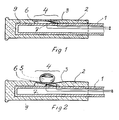
- the tube of the handlebar is made from steel or another rigid material.
- a handle 2 is mounted, not rotatable with respect to the tube 1 but made from an elastically deformable material, which can be e.g. a foamed polyurethane preferably contained in an outer tubular cover 3, forming kind of a skin presenting good abrasion resistance properties.
- a "fixed" handle of the handlebar of a motorcycle is concerned, i.e. not one of the type rotatably mounted onto the support tube 1 normally serving for regulating the gasoline (petrol) supply to the motor.
- the solution shown here can be adapted also to a handle rotatably mounted on the tube 1.
- an outer tubular cover 3 (indicated in the Figures 1 and 2 as an outer skin of the handle) is not indispensable for realising the present invention, insofar as, under the condition that the material of which the handle 2 is made presents the required wear resistance properties as well as elasticity and impermeability, it can replace the outer surface of the handle 2.
- the gripping zone 4 i.e. the zone which plays a fundamental role in the present invention and which is provided with an elastically variable geometry in such a manner that as the pressure exerted by the hand of the driver increases - which is indicated symbolically in the Fig. 2 by the pressing finger 5 - its form and/or its volume changes.
- the gripping zone is laid out as a concave zone i.e. forming a recess 6, which can be pressingly gripped from the outside, as can be seen in the Fig. 2, e.g. using the pressing finger 5.
- the manner in which the gripping zone 4 is activated using a finger 5 is described here merely in the sense of an example, as evidently any other type of gripping action exerted by the hand of the driver (using more fingers or e.g. the entire palm of the hand, etc.) is included within the scope of the application of the present invention.
- the radial extent of the gripping zone 4 formed as a recess 6 does not play a determining role for the effects of the present invention, as it is sufficient that the zone itself be large enough to contain, as on the other hand is necessary for realising the inventive concept, an electric switch and/or a sensor 7, which reacts to variations in form and/or volume of the gripping zone 4.
- a switch 7 is shown, in the sense of a mere example, presenting two contacts, which as shown in the Fig. 1 are open whereas in the Fig. 2 they are shown in their closed state owing to the pressure exerted by the finger 5 onto the gripping zone 4.
- the type of the arrangement applied for reacting to the variations in form and/or volume of the gripping zone 4 does not play any particular role. It is sufficient if the system is reliable and apt to detect the occurrence of variations of the values cited of the gripping zone.
- some preferred types of switches and/or sensors to be applied within the scope of the present invention will be specified more precisely.
- a switch 7 comprising two contacting points, which are closed as the gripping zone 4 is pressed by the finger 5. Closing of the contact of the switch 7 causes activation of a command and/or control device for the function of the vehicle (not shown), which according to a first embodiment of the present invention can be the signal horn of the vehicle, which thus attracts the attention of bystanders. It also can be provided that the command and/or control device to be activated be a horn coupled with the headlights of the vehicle in such a manner that the alarm signal emitted be more effective as now it is an acoustic signal combined with an optical signal more easily perceived by bystanders.
- the commanding and/or controlling device of the vehicle which actually is not indicated in the Figures, be the sequential gear change system.
- the commanding and/or controlling device be the emergency lights of the vehicle.
- the emergency lights usually intermittent red or amber lights arranged on all four sides of the vehicle
- the emergency lights can drastically reduce the danger of rear-end collisions and thus constitutes an optimum solution of one of the most serious problems of road traffic safety.
- command and/or control device in principle can concern the most diverse types of vehicles.
- the gripping zone 4 be incorporated preferentially in a lateral zone at the right or the left of the steering wheel.
- the advantage of this arrangement is evident: these are the positions on the wheel on which the driver preferentially keeps his hands.
- a steering wheel 8 is shown in purely schematic manner, within the right hand side of which the elastically deformable gripping zone 4 is incorporated containing a hollow chamber 6 provided with the two contacting points of a switch which are closed as the gripping zone 4 is pressed by the hand of the driver.
- the cavity 6 for better clarity is shown exaggerated in size and especially in width over the actual dimensions.
- the width of the zone along the circumference of the wheel and the height of the gap containing the switch 7 will be chosen in such a manner that the driver can react within the shortest possible time and with the maximum functional reliability. Determination of the dimensions and the elasticity characteristics to be chosen for the gripping zone, which decisively influence the reliability properties of the inventive arrangement, is left to the specialist in the field, who can determine the right parameters based on suitable tests.
- the gripping zone 4 consist of a tubular deformable external cover 3 filled with an elastically deformable material 9 such as a foamed polyurethane, inside which the electric switch and/or the sensor 7 are located.
- an elastically deformable material 9 such as a foamed polyurethane
- the good elasticity properties of elastomer materials are made use of, from which commanding devices for vehicles can be made, which correspond to the requirements for the layout according to the present invention and are cost-efficient and reliable.
- the electric switch 7 is a piezoelectric switch reacting to an increase in pressure in the gripping zone 4 caused by the variation in form and/or the volume of the gripping zone 4.
- This embodiment does not require any cavity in the gripping zone as it is sufficient that the piezoelectric switch be immersed in the elastic mass forming the zone itself.
- Piezoelectric switches of this type are known today in many fields of technical applications and thus a more detailed description can be dispensed with here as any specialist in the field is able to select the correct type.
- the electric switch and/or the sensor 7 are a pneumatic sensor, or a hydraulic sensor 10 respectively, comprising a chamber 11 containing the fluid, located in the gripping zone 4.
- a hydraulic valve 14 as shown, again in the sense of a mere example, in the Fig. 5.
- the valve 13, or 14 respectively thus represents the connection to at least one command and/or control device (not shown) for the functions of the vehicle.
- the pneumatic valve 13 which can be formed as part of an electric switch apt to interrupt an electric circuit, which is indicated by the two connecting lines 15 and 16
- the hydraulic valve 14 according to the example shown in the Fig. 5 can be connected using two tubes 17 and 18 in which the fluid moves activating the command and/or control circuit of the vehicle.
- the fluid circulating in the tubes 17 and 18 can be a liquid as well as a gas, e.g. air, where the concept of a hydraulic valve 14 is explained in a more general sense of a valve inserted in a circuit in which a fluid circulates.
- the gripping zone 4 is provided with an elastically variable geometry, which in a subsequent installation is mounted on a pre-existing rigid structure, e.g. by installing on the rigid handle 19, donned onto the tube 1, a body 20 presenting the characteristics of elastically deformable geometry and containing inside it the electric switch and/or the sensor 7, which reacts to the variations in the form and/or the volume of the gripping zone 4, or of the body 20 respectively, which is mounted later onto the gripping zone 4.
- the objective of the present invention thus is to enhance the safety of driving vehicles and thus to reduce accidents caused by them.
Landscapes
- Engineering & Computer Science (AREA)
- Mechanical Engineering (AREA)
- Chemical & Material Sciences (AREA)
- Combustion & Propulsion (AREA)
- Transportation (AREA)
- Steering Controls (AREA)
Abstract
Description
- Fig. 1
- a first design example of the present invention applied to the handlebars of a motorcycle, shown in its inactive state;
- Fig. 2
- the inventive device according to the Fig. 1 activated pressure being applied by the hand, or by a finger respectively, of the driver;
- Fig. 3
- another solution adapted, in the sense of an example, to the handlebars of a motorcycle, in which arrangement the gripping zone of the steering device is formed by a body of elastically variable geometry mounted onto a pre-existing rigid structure;
- Fig. 4
- an alternative design example of the present invention, again applied, in the sense of a example, to the handlebars of a motorcycle, in which arrangement the sensor reacting to changes in the form and/or the volume of the gripping zone, is a hydraulic or a pneumatic sensor;
- Fig. 5
- a variant of the solution shown in the Fig. 4, in which furthermore the variations in the form and/or the volume of the gripping zone are transmitted to a pneumatic, or hydraulic, valve;
- Fig. 6
- another variant of the present invention, in which the steering or piloting device is the steering wheel of an automobile the gripping zone preferentially being incorporated in a lateral zone of said steering wheel.
- 1.
- Tube
- 2.
- Handle
- 3.
- Tubular outer cover
- 4.
- Gripping zone
- 5.
- Pressing finger
- 6.
- Cavity
- 7.
- Switch and/or sensor
- 8.
- Steering wheel of an automobile
- 9.
- Elastically deformable material
- 10.
- Pneumatic sensor, or hydraulic sensor respectively
- 11.
- Chamber
- 12.
- Valve
- 13.
- Butterfly valve
- 14.
- Pneumatic valve
- 15.
- Connecting line
- 16.
- Connecting line
- 17.
- Tube
- 18.
- Tube
- 19.
- Rigid handle
- 20.
- Body
Claims (13)
- steering or piloting device for self-propelled vehicles such as motorcycles, automobiles, etc., with a gripping zone, which for steering is gripped with at least one hand and is moved by rotation and/or translation,
characterized in that
the gripping zone (4) is provided with an elastically deformable geometry in such a manner that, as the pressure exerted by the hand (5) of the driver onto it, its form and/or its volume change,
inside the gripping zone (4) an electric switch and/or a sensor (7) is located, which reacts to the changes in form and/or the volume of the gripping zone (4) and that furthermore the electric switch and/or the sensor (7) is connected to at least one command and/or control device of the function of the vehicle, which device thus is activated by the reaction of the electric switch and/or the sensor. - steering or piloting device according to the claim 1,
characterized in that
the steering or piloting device is the steering wheel (8) of an automobile and the gripping zone (4) is incorporated in a preferably lateral zone at the right and/or the left hand side of the wheel. - steering or piloting device according to the claim 1,
characterized in that
the steering or piloting device is a handle (2) of the handlebars of a motorcycle. - steering or piloting device according to the claim 1,
characterized in that
the steering or piloting device is a handle (2) of the control column or joystick of an aircraft. - steering or piloting device according to one of the claims 1 through 4,
characterized in that
the gripping zone (4) is formed by a deformable tubular outer cover (3) filled with an elastically deformable material (9) such as a foamed polyurethane, inside which the electric switch and/or the sensor (7) is contained. - steering or piloting device according to one of the claims 1 through 4,
characterized in that
the electric switch (7) is a switch in which contacts are closed owing to an increase in pressure in the gripping zone (4) caused by the variation in the form and/or the volume of the gripping zone (4). - steering or piloting device according to one of the claims 1 through 4,
characterized in that
the electric switch (7) is a piezoelectric switch, which reacts to an increase in pressure in the gripping zone (4) caused by the variation in the form and/or the volume of the gripping zone (4). - steering or piloting device according to one of the claims 1 through 4,
characterized in that
the electric switch and/or the sensor (7) is a pneumatic sensor, or a hydraulic sensor (10), comprising a chamber (11) located inside the gripping zone (4), containing the fluid, in such a manner that the variations in the form and/or the volume of the gripping zone (4) are transmitted to the fluid, which in turn transmits them to a pneumatic valve (13), or a hydraulic valve (14) respectively, which provides the connection to at least one command and/or control device of the functions of the vehicle. - steering or piloting device according to one of the claims 1 through 8,
characterized in that
the command and/or control device of the vehicle is its signal horn. - steering or piloting device according to the claim 9,
characterized in that
the signal horn is coupled to the controls of the headlights in such a manner that if the horn is honking upon command by the command device also the headlights are turned on. - steering or piloting device according to one of the claims 1 through 8,
characterized in that
the command and/or control device of the vehicle comprises its emergency lights. - steering or piloting device according to one of the claims 1 through 8,
characterized in that
the command and/or control device of the vehicle is its gear change system. - steering or piloting device according to the claim 1,
characterized in that
the gripping zone (4) is provided with an elastically deformable geometry mounted in a later installation on a pre-existing rigid structure (19), comprising a body (20) presenting the desired characteristics of a variable elastic geometry and containing in its inside the electric switch and/or the sensor (7), which reacts to variations in the form and/or the in the volume of the gripping zone (4), or of the body (20) applied later.
Applications Claiming Priority (2)
| Application Number | Priority Date | Filing Date | Title |
|---|---|---|---|
| CH24792000 | 2000-12-20 | ||
| CH24792000 | 2000-12-20 |
Publications (2)
| Publication Number | Publication Date |
|---|---|
| EP1216911A2 true EP1216911A2 (en) | 2002-06-26 |
| EP1216911A3 EP1216911A3 (en) | 2003-02-12 |
Family
ID=4569530
Family Applications (1)
| Application Number | Title | Priority Date | Filing Date |
|---|---|---|---|
| EP01811178A Withdrawn EP1216911A3 (en) | 2000-12-20 | 2001-12-04 | Steering control for self-propelled vehicles |
Country Status (1)
| Country | Link |
|---|---|
| EP (1) | EP1216911A3 (en) |
Cited By (23)
| Publication number | Priority date | Publication date | Assignee | Title |
|---|---|---|---|---|
| DE10209207A1 (en) * | 2002-03-04 | 2003-09-18 | Siemens Ag | Motor vehicle steering wheel with controls has latter operated by pressure pads on steering wheel or handles |
| EP1545002A2 (en) | 2003-12-17 | 2005-06-22 | Lisa Dräxlmaier GmbH | Piezoelectric switch |
| WO2005092698A1 (en) * | 2004-03-26 | 2005-10-06 | Bayerische Motoren Werke Aktiengesellschaft | Control element |
| EP1621442A3 (en) * | 2004-07-29 | 2006-05-24 | Aphrodite Agencies Limited | Steering control for self-propelled vehicles |
| NL2000614C2 (en) * | 2007-04-26 | 2008-10-28 | Tennisplanet Internat B V | Pressure sensor for handle of e.g. tennis racket, has remote-lying elongated contact strips separated away from each other by curved leaf spring, where free ends of spring are attached to carrier |
| GB2450752A (en) * | 2007-07-06 | 2009-01-07 | Richard Alan Clews | Motorcycle warning system activated by unintentional reaction of a rider to a perceived hazard |
| GB2461200A (en) * | 2007-07-06 | 2009-12-30 | Richard Alan Clews | Motorcycle warning system activated by inboard movement of a hand or arm along a handlebar |
| CN102774453A (en) * | 2012-07-04 | 2012-11-14 | 上海跑酷机器人科技有限公司 | Intelligent vehicle balancing system |
| US8516876B2 (en) | 2009-06-10 | 2013-08-27 | Luca Romelli | Method of adjusting an apparatus comprising a flexible tube pre-tensioned with a liquid and connected to a pressure sensor |
| DE202012008121U1 (en) * | 2012-08-27 | 2013-11-28 | Rti Sports Vertrieb Von Sportartikeln Gmbh | bicycle grip |
| WO2014005475A1 (en) * | 2012-07-04 | 2014-01-09 | 上海跑酷机器人科技有限公司 | Smart balanced vehicle system |
| EP2475550A4 (en) * | 2009-09-08 | 2015-05-27 | Adam S Golomb | Integrated vehicle turn signal system and apparatus |
| US9266551B2 (en) | 2009-09-08 | 2016-02-23 | Golomb Mercantile Company Llc | Integrated vehicle control system and apparatus |
| US9272724B2 (en) | 2009-09-08 | 2016-03-01 | Golomb Mercantile Company Llc | Integrated vehicle control system and apparatus |
| CN105492311A (en) * | 2013-10-14 | 2016-04-13 | 宝马股份公司 | Improved control grip |
| EP3042837A1 (en) * | 2015-01-09 | 2016-07-13 | Robert Bosch Gmbh | Handlebar, particularly for a two-wheeled vehicle, with sensor handle |
| CN107531308A (en) * | 2015-03-30 | 2018-01-02 | 本田技研工业株式会社 | The driving-force control apparatus of vehicle |
| CN108116601A (en) * | 2017-12-29 | 2018-06-05 | 金洁琼 | Electric bicycle handlebar covers mechanical breaker device |
| CN111620272A (en) * | 2020-04-24 | 2020-09-04 | 诺力智能装备股份有限公司 | Control device suitable for industrial vehicle |
| JP2020158061A (en) * | 2019-03-28 | 2020-10-01 | 川崎重工業株式会社 | vehicle |
| CN112141248A (en) * | 2020-10-14 | 2020-12-29 | 上海理工大学 | A vehicle handle with a measurable contact area |
| CN112849117A (en) * | 2019-11-12 | 2021-05-28 | 合肥杰发科技有限公司 | Steering wheel adjusting method and related device thereof |
| WO2021219343A1 (en) * | 2020-04-27 | 2021-11-04 | Tdk Electronics Ag | Control element and vehicle with control element |
Family Cites Families (4)
| Publication number | Priority date | Publication date | Assignee | Title |
|---|---|---|---|---|
| US1740634A (en) * | 1927-07-19 | 1929-12-24 | Jules L Wettlaufer | Vehicle indicator switch |
| BR7600286A (en) * | 1975-01-21 | 1976-08-31 | Lucas Industries Ltd | ELECTRIC KEY FOR USE IN ELECTRICALLY ASSISTED BIKE AND THEIR ELECTRICALLY ASSISTED BIKE |
| DE4130965A1 (en) * | 1991-09-18 | 1993-03-25 | Dietrich Gebhard | WARNING TURN SIGNAL FOR A MOTOR VEHICLE |
| DE19927464B4 (en) * | 1999-06-16 | 2008-09-04 | Volkswagen Ag | Steering wheel with feeler elements |
-
2001
- 2001-12-04 EP EP01811178A patent/EP1216911A3/en not_active Withdrawn
Cited By (39)
| Publication number | Priority date | Publication date | Assignee | Title |
|---|---|---|---|---|
| DE10209207B4 (en) * | 2002-03-04 | 2008-08-28 | Siemens Ag | Steering wheel with controls |
| DE10209207A1 (en) * | 2002-03-04 | 2003-09-18 | Siemens Ag | Motor vehicle steering wheel with controls has latter operated by pressure pads on steering wheel or handles |
| EP1545002A2 (en) | 2003-12-17 | 2005-06-22 | Lisa Dräxlmaier GmbH | Piezoelectric switch |
| EP1545002A3 (en) * | 2003-12-17 | 2008-07-09 | Lisa Dräxlmaier GmbH | Piezoelectric switch |
| US7564170B2 (en) | 2003-12-17 | 2009-07-21 | Lisa Dräxlmaier GmbH | Piezoswitch |
| WO2005092698A1 (en) * | 2004-03-26 | 2005-10-06 | Bayerische Motoren Werke Aktiengesellschaft | Control element |
| CN100453398C (en) * | 2004-03-26 | 2009-01-21 | 宝马股份公司 | Operating parts |
| US7980155B2 (en) | 2004-03-26 | 2011-07-19 | Bayerische Motoren Werke Aktiengesellschaft | Operating element |
| US7954399B2 (en) | 2004-07-29 | 2011-06-07 | Aphrodite Agencies Limited | Steering control for self-propelled vehicles |
| EP1621442A3 (en) * | 2004-07-29 | 2006-05-24 | Aphrodite Agencies Limited | Steering control for self-propelled vehicles |
| NL2000614C2 (en) * | 2007-04-26 | 2008-10-28 | Tennisplanet Internat B V | Pressure sensor for handle of e.g. tennis racket, has remote-lying elongated contact strips separated away from each other by curved leaf spring, where free ends of spring are attached to carrier |
| GB2450752B (en) * | 2007-07-06 | 2009-12-02 | Richard Alan Clews | Motorcycle warning system |
| GB2461200B (en) * | 2007-07-06 | 2010-06-16 | Richard Alan Clews | Motorcycle warning system |
| GB2461200A (en) * | 2007-07-06 | 2009-12-30 | Richard Alan Clews | Motorcycle warning system activated by inboard movement of a hand or arm along a handlebar |
| GB2450752A (en) * | 2007-07-06 | 2009-01-07 | Richard Alan Clews | Motorcycle warning system activated by unintentional reaction of a rider to a perceived hazard |
| US8516876B2 (en) | 2009-06-10 | 2013-08-27 | Luca Romelli | Method of adjusting an apparatus comprising a flexible tube pre-tensioned with a liquid and connected to a pressure sensor |
| EP2475550A4 (en) * | 2009-09-08 | 2015-05-27 | Adam S Golomb | Integrated vehicle turn signal system and apparatus |
| US10272939B2 (en) | 2009-09-08 | 2019-04-30 | Golomb Mercantile Company Llc | Integrated vehicle control system and apparatus |
| US9272724B2 (en) | 2009-09-08 | 2016-03-01 | Golomb Mercantile Company Llc | Integrated vehicle control system and apparatus |
| US9266551B2 (en) | 2009-09-08 | 2016-02-23 | Golomb Mercantile Company Llc | Integrated vehicle control system and apparatus |
| WO2014005475A1 (en) * | 2012-07-04 | 2014-01-09 | 上海跑酷机器人科技有限公司 | Smart balanced vehicle system |
| CN102774453A (en) * | 2012-07-04 | 2012-11-14 | 上海跑酷机器人科技有限公司 | Intelligent vehicle balancing system |
| CN102774453B (en) * | 2012-07-04 | 2015-05-20 | 上海跑酷机器人科技有限公司 | Intelligent vehicle balancing system |
| EP2703275A3 (en) * | 2012-08-27 | 2015-03-25 | RTI Sports Vertrieb von Sportartikeln GmbH | Bicycle handle-bar grip |
| DE202012008121U1 (en) * | 2012-08-27 | 2013-11-28 | Rti Sports Vertrieb Von Sportartikeln Gmbh | bicycle grip |
| CN105492311A (en) * | 2013-10-14 | 2016-04-13 | 宝马股份公司 | Improved control grip |
| US20160152298A1 (en) * | 2013-10-14 | 2016-06-02 | Bayerische Motoren Werke Aktiengesellschaft | Control Grip for a Vehicle |
| CN105492311B (en) * | 2013-10-14 | 2018-06-01 | 宝马股份公司 | Improved joystick |
| EP3042837A1 (en) * | 2015-01-09 | 2016-07-13 | Robert Bosch Gmbh | Handlebar, particularly for a two-wheeled vehicle, with sensor handle |
| CN107531308A (en) * | 2015-03-30 | 2018-01-02 | 本田技研工业株式会社 | The driving-force control apparatus of vehicle |
| CN108116601A (en) * | 2017-12-29 | 2018-06-05 | 金洁琼 | Electric bicycle handlebar covers mechanical breaker device |
| JP2020158061A (en) * | 2019-03-28 | 2020-10-01 | 川崎重工業株式会社 | vehicle |
| US11884354B2 (en) | 2019-03-28 | 2024-01-30 | Kawasaki Motors, Ltd. | Vehicle |
| CN112849117A (en) * | 2019-11-12 | 2021-05-28 | 合肥杰发科技有限公司 | Steering wheel adjusting method and related device thereof |
| CN111620272A (en) * | 2020-04-24 | 2020-09-04 | 诺力智能装备股份有限公司 | Control device suitable for industrial vehicle |
| WO2021219343A1 (en) * | 2020-04-27 | 2021-11-04 | Tdk Electronics Ag | Control element and vehicle with control element |
| JP2023522230A (en) * | 2020-04-27 | 2023-05-29 | ティーディーケイ・エレクトロニクス・アクチェンゲゼルシャフト | Control elements and vehicles with control elements |
| JP7592104B2 (en) | 2020-04-27 | 2024-11-29 | ティーディーケイ・エレクトロニクス・アクチェンゲゼルシャフト | Operating element and vehicle equipped with operating element |
| CN112141248A (en) * | 2020-10-14 | 2020-12-29 | 上海理工大学 | A vehicle handle with a measurable contact area |
Also Published As
| Publication number | Publication date |
|---|---|
| EP1216911A3 (en) | 2003-02-12 |
Similar Documents
| Publication | Publication Date | Title |
|---|---|---|
| EP1216911A2 (en) | Steering control for self-propelled vehicles | |
| EP3000684B1 (en) | Straddle type vehicle with approach notification device | |
| JP2001505841A (en) | Steering device with measured value transmission device | |
| US9018551B2 (en) | Handlebar switch for motorcycle | |
| US6153996A (en) | Steering device with an actuating ring | |
| KR20210084722A (en) | control system for vehicle | |
| US2824462A (en) | Steering wheel mounted control device | |
| CN2790870Y (en) | Easy-to-drive steering wheel | |
| KR100382268B1 (en) | An automatic vehicle driving information apparatus | |
| CN217553981U (en) | Automobile driving auxiliary system and vehicle | |
| KR100280666B1 (en) | Car emergency light flasher | |
| KR20020033141A (en) | Automotive Acceleration Aids (Accelerator Aids) | |
| KR200196339Y1 (en) | Emergency lighting device of vehicle | |
| KR200140929Y1 (en) | Variable accelerator pedal in a car | |
| KR100280851B1 (en) | Vehicle driving control device | |
| KR100622715B1 (en) | Emergency light flasher switch automatically activated in case of emergency | |
| KR100402770B1 (en) | Safety Appatus for Automobile Steering System | |
| CA3195280A1 (en) | Sws (snow wizard system) | |
| KR19980044951U (en) | Emergency lamp operating device of car | |
| KR870005843A (en) | Controllers for Wheeled Construction Equipment | |
| BG112872A (en) | On-board electric vehicle control system | |
| KR920003419Y1 (en) | Vehicle emergency brake system | |
| KR970074176A (en) | Safety steering angle display device of automobile | |
| JP2008254505A (en) | Rudder angle control device | |
| KR20020051723A (en) | a shimmy prevention structure of steering wheel of vehicles |
Legal Events
| Date | Code | Title | Description |
|---|---|---|---|
| PUAI | Public reference made under article 153(3) epc to a published international application that has entered the european phase |
Free format text: ORIGINAL CODE: 0009012 |
|
| AK | Designated contracting states |
Kind code of ref document: A2 Designated state(s): AT BE CH CY DE DK ES FI FR GB GR IE IT LI LU MC NL PT SE TR |
|
| AX | Request for extension of the european patent |
Free format text: AL;LT;LV;MK;RO;SI |
|
| PUAL | Search report despatched |
Free format text: ORIGINAL CODE: 0009013 |
|
| AK | Designated contracting states |
Designated state(s): AT BE CH CY DE DK ES FI FR GB GR IE IT LI LU MC NL PT SE TR |
|
| AX | Request for extension of the european patent |
Extension state: AL LT LV MK RO SI |
|
| 17P | Request for examination filed |
Effective date: 20030812 |
|
| AKX | Designation fees paid |
Designated state(s): AT BE CH CY DE DK ES FI FR GB GR IE IT LI LU MC NL PT SE TR |
|
| 17Q | First examination report despatched |
Effective date: 20031203 |
|
| 17Q | First examination report despatched |
Effective date: 20031203 |
|
| STAA | Information on the status of an ep patent application or granted ep patent |
Free format text: STATUS: THE APPLICATION IS DEEMED TO BE WITHDRAWN |
|
| 18D | Application deemed to be withdrawn |
Effective date: 20070918 |