EP1216856B2 - Anhängevorrichtung für ein Arbeitsfahrzeug - Google Patents
Anhängevorrichtung für ein Arbeitsfahrzeug Download PDFInfo
- Publication number
- EP1216856B2 EP1216856B2 EP01130371A EP01130371A EP1216856B2 EP 1216856 B2 EP1216856 B2 EP 1216856B2 EP 01130371 A EP01130371 A EP 01130371A EP 01130371 A EP01130371 A EP 01130371A EP 1216856 B2 EP1216856 B2 EP 1216856B2
- Authority
- EP
- European Patent Office
- Prior art keywords
- coupling
- ball
- holding
- trailer
- trailer coupling
- Prior art date
- Legal status (The legal status is an assumption and is not a legal conclusion. Google has not performed a legal analysis and makes no representation as to the accuracy of the status listed.)
- Expired - Lifetime
Links
Images


Classifications
-
- B—PERFORMING OPERATIONS; TRANSPORTING
- B60—VEHICLES IN GENERAL
- B60D—VEHICLE CONNECTIONS
- B60D1/00—Traction couplings; Hitches; Draw-gear; Towing devices
- B60D1/58—Auxiliary devices
- B60D1/583—Holding-down means, e.g. holding-down retainers
-
- A—HUMAN NECESSITIES
- A01—AGRICULTURE; FORESTRY; ANIMAL HUSBANDRY; HUNTING; TRAPPING; FISHING
- A01B—SOIL WORKING IN AGRICULTURE OR FORESTRY; PARTS, DETAILS, OR ACCESSORIES OF AGRICULTURAL MACHINES OR IMPLEMENTS, IN GENERAL
- A01B59/00—Devices specially adapted for connection between animals or tractors and agricultural machines or implements
- A01B59/04—Devices specially adapted for connection between animals or tractors and agricultural machines or implements for machines pulled or pushed by a tractor
- A01B59/042—Devices specially adapted for connection between animals or tractors and agricultural machines or implements for machines pulled or pushed by a tractor having pulling means arranged on the rear part of the tractor
-
- B—PERFORMING OPERATIONS; TRANSPORTING
- B60—VEHICLES IN GENERAL
- B60D—VEHICLE CONNECTIONS
- B60D1/00—Traction couplings; Hitches; Draw-gear; Towing devices
- B60D1/01—Traction couplings or hitches characterised by their type
- B60D1/06—Ball-and-socket hitches
-
- B—PERFORMING OPERATIONS; TRANSPORTING
- B60—VEHICLES IN GENERAL
- B60D—VEHICLE CONNECTIONS
- B60D1/00—Traction couplings; Hitches; Draw-gear; Towing devices
- B60D1/01—Traction couplings or hitches characterised by their type
- B60D1/06—Ball-and-socket hitches
- B60D1/065—Ball-and-socket hitches characterised by the hitch mechanism
-
- B—PERFORMING OPERATIONS; TRANSPORTING
- B60—VEHICLES IN GENERAL
- B60D—VEHICLE CONNECTIONS
- B60D1/00—Traction couplings; Hitches; Draw-gear; Towing devices
- B60D1/24—Traction couplings; Hitches; Draw-gear; Towing devices characterised by arrangements for particular functions
- B60D1/42—Traction couplings; Hitches; Draw-gear; Towing devices characterised by arrangements for particular functions for being adjustable
- B60D1/46—Traction couplings; Hitches; Draw-gear; Towing devices characterised by arrangements for particular functions for being adjustable vertically
- B60D1/465—Traction couplings; Hitches; Draw-gear; Towing devices characterised by arrangements for particular functions for being adjustable vertically comprising a lifting mechanism, e.g. for coupling while lifting
-
- B—PERFORMING OPERATIONS; TRANSPORTING
- B60—VEHICLES IN GENERAL
- B60D—VEHICLE CONNECTIONS
- B60D1/00—Traction couplings; Hitches; Draw-gear; Towing devices
- B60D1/48—Traction couplings; Hitches; Draw-gear; Towing devices characterised by the mounting
- B60D1/54—Traction couplings; Hitches; Draw-gear; Towing devices characterised by the mounting collapsible or retractable when not in use, e.g. hide-away hitches
Definitions
- the invention relates to a trailer system for an agricultural or industrial vehicle with a vertically pivotable between an upper transport position and a lowered position hinged to the vehicle body frame part.
- the free, pivotable end of the frame part receives a projecting, directly or indirectly guided by the frame part and lockable in at least one vehicle longitudinal position coupling part.
- Such attachment systems are commonly referred to as pick-up hitch.
- Such a trailer system according to the preamble is by the EP-A-0 695 655 has become known, which refers to an immediate determination between a designated traction element coupling part and the vehicle body.
- the tension element described therein is either designed as a conventional drawbar or it contains a conventional upstanding hitch hook (ISO 6489-1), which serves as a pulling or carrying device for the trailer eye of an attached device.
- the load on the drawbar or hitch hook is limited and does not always meet the requirements of the practice.
- the vertical load on the Hitch hook must not exceed 30 kN (approx. 3 t).
- This support load limits the load capacity of the vehicle during intensive transport work, although a higher load would in principle be possible due to the low-lying position of the trailer attachment system on the tractor.
- a relatively high wear is generated by the high vertical support loads in the support surface between the hitch hook and the trailer lug, which can not be limited to satisfactory values due to the existing geometry of the components, which allow a relative movement to each other in the engaged state.
- the coupling carrier is rigidly attached to the coupling ball on the vehicle chassis.
- this coupling device the coupling process is difficult because, on the one hand, the operator can not see the coupling point from the driver's cab. It is therefore an assistant required, or the operator must leave the cab several times for coupling.
- a lifting device for the drawbar of the trailer is needed to bring it to the height of the coupling ball.
- the object underlying the invention is seen to provide a trailer system of the type mentioned, by which the aforementioned problems are overcome.
- the attachment system should be suitable to accommodate higher than usual support loads.
- wear phenomena should be minimized and the coupling process should be facilitated.
- the attachment system includes a vertically in the vertical direction between an upper transport position and a lowered position hinged to the vehicle body frame part.
- the free, pivotable end of the frame part receives a projecting, directly or indirectly guided by the frame part and lockable in at least one vehicle longitudinal position coupling part.
- the coupling part contains a coupling ball.
- the bearing surfaces can be considerably larger than known solutions, so that an improvement of the function (increase of the permissible support loads) is achieved.
- the clutch parts serving coupling parts - coupling ball and counter-pan of the device to be coupled - can be coordinated so that forms a substantially backlash-free connection.
- the time stability improvement of the wear behavior
- the coupling ball is not attached to a fixed predetermined location on the vehicle chassis, but on a height and length adjustable attachment system.
- This makes it possible to set the vehicle-mounted dome point to the respective height of the hitch for coupling the hitch of a trailer drawbar, in particular lowered from its lockable base or transport position, can be. Tools for lifting the trailer drawbar are not required.
- the dome point in the vehicle longitudinal direction can be extended so far that it is visible from the driver's seat of the vehicle platform, which considerably simplifies the dome operation and makes the involvement of a second person superfluous.
- the advantages of a movable pick-up hitch are combined with those of a ball coupling.
- the coupling ball in the upper region of the outermost free end of the coupling part.
- the extending in the vehicle longitudinal direction free end of the coupling part can extend in an upwardly curved arc and end in a coupling ball.
- a preferred embodiment of the invention provides that a holding device is attached to the coupling part, which serves to lock the coupling part on the vehicle body.
- the locking can take place on a locking device fastened directly to the vehicle body or on a locking device which is mounted on a component fastened to the vehicle body.
- the holding device is a substantially projecting from the coupling part up tab, which has a horizontal transverse recess.
- the transverse recess serves to receive a locking bolt, by means of which the attachment system, in particular the coupling part and the frame part, can be locked in the upper transport position relative to the vehicle body.
- the coupling part is formed with the coupling ball and optionally with the holding device as a one-piece forging, which is able to absorb high tensile and compressive forces.
- said parts may be connected to each other inseparably in other ways.
- a holding-down device which secures a coupling device mounted on the coupling ball, provided that the attachment system is in the transport position.
- the hold-down is expediently two protruding tabs which are aligned substantially parallel to one another and each have a transverse recess which corresponds to the transverse recess of the tab of the holding device, provided that the frame part and the holding device assume the transport position.
- the tabs can accommodate locking bolts.
- the attachment system shown essentially consists of an upper frame member 10, a lower frame member 12, a guide member 14 and a coupling member 16.
- the upper frame member 10 includes mounting plates 18, 20 with mounting holes, the rigid attachment of the upper frame member 10 to a Schuachsdifferentialgereheatuse not shown serve a tractor, with the mounting plate 20 is located at the rear end of the tractor. Because of the rigid attachment, the upper frame member 10 may be considered part of the vehicle body.
- the rear vertically oriented mounting plate 20 carries a hold-down 22, which consists essentially of two mutually parallel and vertically aligned, rearwardly projecting hold-down tabs 24, 26.
- the covered by a stiffening plate 27 hold-down tabs 24, 26 each include a transverse bore 28.
- the transverse bores 28 correspond to each other and serve to receive a locking pin, not shown, a locking device 30.
- the locking device 30 is in accordance with Fig. 1 right hold-down tab 26 screwed. It is, for example, a locking device whose training and operation in the EP-A-0 695 655 has been described.
- a transverse to the vehicle longitudinal direction and horizontally oriented pivot axis 32 is formed, on which the front end of the lower frame member 12 is articulated.
- two bolts 34 oriented transversely outwards and in the horizontal direction are fastened to the lower frame part. At these bolts 34 can fix the ends of a lifting link, not shown, through which the lower frame member 12 can pivot about the pivot axis 32 to raise or lower the rear end thereof.
- the lower frame part 12 is formed in the manner of a cassette and includes a substantially rectangular channel in which the guide member 14 is guided displaceably in the vehicle longitudinal direction.
- a hydraulic cylinder for displacement of the guide member 14, is used, one end of which acts on the pivot axis 32 and the other end on the guide member 14.
- the coupling member 16 by at least one screw, not shown, which extends through a recess 35 of the coupling part 16, attached.
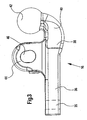
- the coupling part 16 goes out Fig. 3 out. It includes a front portion 36 which is formed substantially rectangular in shape and in a correspondingly shaped channel in the guide member 14 can be inserted.
- the rear end 38 of the rectangular portion 36 merges into an arcuate ball neck 40, the upper end of which carries a coupling ball 42 projecting upwards and rearwards over the rest of the attachment system.
- the coupling ball 42 is thus at the extreme rear end of the coupling part 16.
- the coupling part 16 From the central region of the coupling part 16 is formed as a tab 44 holding device upwards, which has a transverse, horizontal transverse recess 46.
- the transverse recess 46 of the tab 44 is aligned with the transverse bores 28 in the hold-down tabs 24, 26, so that a locking bolt of the locking device 30 is inserted and the coupling part 16 can be set directly opposite the vehicle-fixed upper frame part 10.
- the recess has a slightly oval cross-section, which is slightly narrower at the top than below, whereby the locking and finding a defined transport position is facilitated.
- the coupling part 16 is a forged part and formed integrally with the coupling ball 42 and the tab 44.
- the coupling ball 42 serves to receive a coupling device, not shown, which includes a ball socket, which is mounted, for example, at the front free end of a trailer drawbar.
- a coupling device not shown
- the hold-down tabs 24, 26 have in their rear, lower region a circular shape 48, which is adapted to the spherical surface of the coupling ball 42.
- the hold-down tabs 24, 26 thus ensure, whenever the attachment system assumes its upper transport position, a ball socket received by the coupling ball 42. If, after loosening the locking device 30, the suspension system is pivoted downwards out of its transport position, the ball socket exits from the area of influence of the hold-down tabs 24, 26, so that it can lift itself off the coupling ball 42 and release it.
Landscapes
- Engineering & Computer Science (AREA)
- Mechanical Engineering (AREA)
- Transportation (AREA)
- Life Sciences & Earth Sciences (AREA)
- Zoology (AREA)
- Soil Sciences (AREA)
- Environmental Sciences (AREA)
- Agricultural Machines (AREA)
- Vehicle Cleaning, Maintenance, Repair, Refitting, And Outriggers (AREA)
- Lifting Devices For Agricultural Implements (AREA)
Description
- Die Erfindung betrifft ein Anhängesystem für ein landwirtschaftliches oder industrielles Fahrzeug mit einem in vertikaler Richtung zwischen einer oberen Transportstellung und einer abgesenkten Stellung schwenkbar am Fahrzeugrumpf angelenkten Rahmenteil. Das freie, verschwenkbare Ende des Rahmenteils nimmt ein vorstehendes, unmittelbar oder mittelbar vom Rahmenteil geführtes und in wenigstens einer Fahrzeuglängsposition arretierbares Kupplungsteil auf. Derartige Anhängesysteme werden üblicherweise mit Pick-up Hitch bezeichnet.
- Ein derartiges Anhängesystem dem Oberbegriff entsprechend ist durch die
EP-A-0 695 655 bekannt geworden, die sich auf eine unmittelbare Festlegung zwischen einem mit Zugelement bezeichnetem Kupplungsteil und dem Fahrzeugrumpf bezieht. Das dort beschriebene Zugelement ist entweder als übliches Zugpendel ausgebildet oder es enthält einen üblichen nach oben stehenden Hitch-Haken (ISO 6489-1), der als Zug- oder Trageinrichtung für die Anhängeröse eines angehängten Gerätes dient. - Die Stützlast am Zug- oder Hitch-Haken ist jedoch begrenzt und entspricht nicht immer den Anforderungen der Praxis. So darf bei landwirtschaftlichen Traktoren die Stützlast am Hitch-Haken 30 kN (etwa 3 t) nicht überschreiten. Diese Stützlast begrenzt bei intensiver Transportarbeit die Belastbarkeit des Fahrzeugs, obwohl durch die tiefliegende Position des Anhängesystems am Traktor eine höhere Belastung grundsätzlich möglich wäre. Des weiteren wird durch die hohen vertikalen Stützlasten in der Auflagefläche zwischen dem Hitch-Haken und der Anhängeröse ein relativ hoher Verschleiß erzeugt, der wegen der bestehenden Geometrie der Bauteile, die im eingekuppelten Zustand eine Relativbewegung zueinander zulassen, nicht auf befriedigende Werte begrenzt werden kann.
- Durch die
WO-A-00/66376 - Der Kupplungsträger ist mit der Kupplungskugel starr am Fahrzeugchassis befestigt. Mit dieser Kupplungsvorrichtung ist der Kuppelvorgang jedoch schwierig, denn einerseits kann die Bedienungsperson von der Fahrerkabine aus den Kuppelpunkt nicht einsehen. Es ist daher eine Hilfsperson erforderlich, oder die Bedienungsperson muss zum Kuppeln mehrfach die Fahrerkabine verlassen. Andererseits wird insbesondere bei schweren Geräten eine Hubeinrichtung für die Deichsel des Anhängers benötigt, um diese auf die Höhe der Kupplungskugel zu bringen.
- Aus der
US-A-2 966 369 ist eine weitere Kupplungsvorrichtung bekannt, bei welcher die dort vorgesehene Kupplungkugel federnd bzw. gedämpft gelagert ist. - Die der Erfindung zugrunde liegende Aufgabe wird darin gesehen, ein Anhängesystem der eingangs genannten Art anzugeben, durch welches die vorgenannten Probleme überwunden werden. Insbesondere soll das Anhängesystem geeignet sein, höhere als bisher übliche Stützlasten aufzunehmen. Des Weiteren sollen Verschleißerscheinungen minimiert und der Kuppelvorgang erleichtert werden.
- Die Aufgabe wird erfindungsgemäß durch die Lehre des Patentanspruchs 1 gelöst. Weitere vorteilhafte Ausgestaltungen und Weiterbildungen der Erfindung gehen aus den Unteransprüchen hervor.
- Das erfindungsgemäße Anhängesystem enthält ein in vertikaler Richtung zwischen einer oberen Transportstellung und einer abgesenkten Stellung schwenkbar am Fahrzeugrumpf angelenktes Rahmenteil. Das freie, verschwenkbare Ende des Rahmenteils nimmt ein vorstehendes, unmittelbar oder mittelbar vom Rahmenteil geführtes und in wenigstens einer Fahrzeuglängsposition arretierbares Kupplungsteil auf. Es wird vorgeschlagen, dass das Kupplungsteil eine Kupplungskugel enthält.
- Durch die Verwendung einer Kugel als Stützlager lassen sich die Auflageflächen gegenüber bekannten Lösungen erheblich vergrößern, so dass eine Verbesserung der Funktion (Erhöhung der zulässigen Stützlasten) erreicht wird. Die der Kupplung dienenden Kupplungsteile - Kupplungskugel und Gegenpfanne des zu kuppelnden Gerätes - lassen sich derart aufeinander abstimmen, dass sich eine im wesentlichen spielfreie Verbindung ausbildet. Damit kann auch die Zeitfestigkeit (Verbesserung des Verschleißverhaltens) erheblich verbessert werden.
- Erfindungsgemäß ist die Kupplungskugel nicht an einem fest vorgegebenen Ort am Fahrzeugchassis befestigt, sondern an einem höhen- und längenverstellbaren Anhängesystem. Dies ermöglicht es, dass zum Kuppeln der Anhängevorrichtung einer Anhängerdeichsel der fahrzeugfeste Kuppelpunkt auf die jeweilige Höhe der Anhängevorrichtung eingestellt, insbesondere aus seiner verriegelbaren Grund- oder Transportstellung abgesenkt, werden kann. Hilfsmittel zum Anheben der Anhängerdeichsel sind nicht erforderlich. Des Weiteren lässt sich der Kuppelpunkt in Fahrzeuglängsrichtung so weit ausfahren, dass er von dem Fahrerplatz der Fahrzeugplattform aus sichtbar ist, was den Kuppelvorgang erheblich vereinfacht und die Mitwirkung einer zweiten Person entbehrlich macht. Es werden somit die Vorteile einer beweglichen Pick-up Hitch mit denen einer Kugelkupplung kombiniert.
- Für eine gute Einsehbarkeit beim Kuppelvorgang ist es von besonderem Vorteil, die Kupplungskugel im oberen Bereich des äußersten freien Endes des Kupplungsteils anzuordnen. Insbesondere kann das sich in Fahrzeuglängsrichtung erstreckende freie Ende des Kupplungsteils in einem nach oben gekrümmten Bogen verlaufen und in einer Kupplungskugel enden.
- Um hohen Kräften standhalten zu können, ohne die Bauteile übermäßig dimensionieren zu müssen, ist es vorteilhaft, das Kupplungsteil und die Kupplungskugel nicht als gesonderte Teile bereitzustellen, sondern einteilig, unlösbar mit einander verbunden auszubilden.
- Eine bevorzugte Ausgestaltung der Erfindung sieht vor, dass am Kupplungsteil eine Haltevorrichtung angebracht ist, die der Arretierung des Kupplungsteils am Fahrzeugrumpf dient. Die Arretierung kann an einer unmittelbar am Fahrzeugrumpf befestigten Arretiervorrichtung oder an einer Arretiervorrichtung, die an einem am Fahrzeugrumpf befestigten Bauteil montiert ist, erfolgen.
- Dabei ist es zweckmäßig, die Haltevorrichtung als eine im wesentlichen von dem Kupplungsteil nach oben vorstehende Lasche auszubilden, die eine horizontale Querausnehmung aufweist. Die Querausnehmung dient der Aufnahme eines Arretierbolzens, durch welchen sich das Anhängesystem, insbesondere das Kupplungsteil und das Rahmenteil, in der oberen Transportstellung gegenüber dem Fahrzeugrumpf arretieren lässt.
- Vorzugsweise ist das Kupplungsteil mit der Kupplungskugel und gegebenenfalls mit der Haltevorrichtung als ein einteiliges Schmiedeteil ausgebildet, welches hohe Zug- und Druckkräfte aufzunehmen vermag. Die genannten Teile können jedoch auch auf andere Weise unlösbar miteinander verbunden sein.
- Unmittelbar am Fahrzeugrumpf oder an einem an dem Fahrzeugrumpf befestigten Bauteil ist ein Niederhalter angeordnet, der eine auf der Kupplungskugel montierte Kupplungsvorrichtung sichert, sofern sich das Anhängesystem in Transportstellung befindet. Bei dem Niederhalter handelt es sich zweckmäßigerweise um zwei im wesentlichen parallel zueinander ausgerichtete vorstehende Laschen, die jeweils eine Querausnehmung aufweisen, die mit der Querausnehmung der Lasche der Haltevorrichtung korrespondieren, sofern das Rahmenteil und die Haltevorrichtung die Transportstellung einnehmen. Die Laschen können Arretierbolzen aufnehmen.
- Anhand der Zeichnung, die ein Ausführungsbeispiel der Erfindung zeigt, werden nachfolgend die Erfindung sowie weitere Vorteile und vorteilhafte Weiterbildungen und Ausgestaltungen der Erfindung näher beschrieben und erläutert.
- Es zeigt:
- Fig. 1
- die perspektivische Ansicht eines erfindungsgemäßen Anhängesystems,
- Fig. 2
- eine Seitenansicht des Anhängesystems gemäß
Fig. 2 und - Fig. 3
- ein Kupplungsteil mit integrierter Kupplungskugel und Befestigungslasche.
- Das in den
Figuren 1 und2 dargestellte Anhängesystem besteht im wesentlichen aus einem oberen Rahmenteil 10, einem unteren Rahmenteil 12, einem Führungsteil 14 und einem Kupplungsteil 16. Das obere Rahmenteil 10 enthält Befestigungsplatten 18, 20 mit Befestigungsbohrungen, die der starren Befestigung des oberen Rahmenteils 10 an einem nicht näher dargestellten Hinterachsdifferentialgehäuse eines Ackerschleppers dienen, wobei sich die Befestigungsplatte 20 am hinteren Schlepperende befindet. Wegen der starren Befestigung kann das obere Rahmenteil 10 als Teil des Fahrzeugrumpfs angesehen werden. - Die hintere senkrecht ausgerichtete Befestigungsplatte 20 trägt einen Niederhalter 22, welcher im wesentlichen aus zwei parallel zueinander und senkrecht ausgerichteten, nach hinten vorstehenden Niederhalterlaschen 24, 26 besteht. Die durch eine Versteifungsplatte 27 abgedeckten Niederhalterlaschen 24, 26 enthalten je eine Querbohrung 28. Die Querbohrungen 28 korrespondieren miteinander und dienen der Aufnahme eines nicht näher dargestellten Arretierbolzens einer Verriegelungseinrichtung 30. Die Verriegelungseinrichtung 30 ist an der gemäß
Fig. 1 rechten Niederhalterlasche 26 festgeschraubt. Es handelt sich beispielsweise um eine Arretiereinrichtung, deren Ausbildung und Funktionsweise in derEP-A-0 695 655 beschrieben wurde. - Im vorderen Bereich des oberen Rahmenteils 10 ist eine quer zur Fahrzeuglängsrichtung und horizontal ausgerichtete Schwenkachse 32 ausgebildet, an der das vordere Ende des unteren Rahmenteils 12 angelenkt ist. Im Bereich des hinteren Endes sind an dem unteren Rahmenteil zwei quer nach außen und in horizontaler Richtung ausgerichtete Bolzen 34 befestigt. An diesen Bolzen 34 lassen sich die Enden eines nicht dargestellten Hubgestänges befestigen, durch die sich das untere Rahmenteil 12 um die Schwenkachse 32 verschwenken lässt, um dessen hinteres Ende anzuheben oder abzusenken.
- Das untere Rahmenteil 12 ist nach Art einer Kassette ausgebildet und enthält einen im wesentlichen rechteckigen Kanal, in dem das Führungsteil 14 in Fahrzeuglängsrichtung verschiebbar geführt ist. Zur Verschiebung des Führungsteils 14 wird ein nicht dargestellter Hydraulikzylinder verwendet, dessen eines Ende an der Schwenkachse 32 und dessen anderes Ende an dem Führungsteil 14 angreift.
- Am hinteren Ende des Führungsteils 14 ist das Kupplungsteil 16 durch wenigstens eine nicht näher dargestellte Schraube, die sich durch eine Ausnehmung 35 des Kupplungsteils 16 erstreckt, befestigt. Das Kupplungsteil 16 geht aus
Fig. 3 hervor. Es enthält einen vorderen Abschnitt 36, der im wesentlichen rechteckförmig ausgebildet ist und in einen entsprechend ausgebildeten Kanal im Führungsteil 14 einführbar ist. Das hintere Ende 38 des rechteckigen Abschnitts 36 geht in einen bogenförmig ausgebildeten Kugelhals 40 über, dessen oberes Ende eine nach oben und hinten über das übrige Anhängesystem vorstehende Kupplungskugel 42 trägt. Die Kupplungskugel 42 liegt damit am äußersten hinteren Ende des Kupplungsteils 16. - Vom mittleren Bereich des Kupplungsteils 16 steht eine als Lasche 44 ausgebildete Haltevorrichtung nach oben vor, die eine quer verlaufende, horizontale Querausnehmung 46 aufweist. Wenn das Anhängesystem seine obere Transportstellung (
Fig. 2 ) einnimmt, fluchtet die Querausnehmung 46 der Lasche 44 mit den Querbohrungen 28 in den Niederhalterlaschen 24, 26, so dass ein Sicherungsbolzen der Verriegelungseinrichtung 30 eingeführt und das Kupplungsteil 16 unmittelbar gegenüber dem fahrzeugfesten oberen Rahmenteil 10 festgelegt werden kann. - Wie aus
Fig. 3 hervorgeht, hat die Ausnehmung einen leicht ovalen Querschnitt, der oben etwas enger ist als unten, wodurch das Verriegeln und Auffinden einer definierten Transportstellung erleichtert wird. Das Kupplungsteil 16 ist ein Schmiedeteil und mit der Kupplungskugel 42 und der Lasche 44 einteilig ausgebildet. - Die Kupplungskugel 42 dient der Aufnahme einer nicht dargestellten Kupplungsvorrichtung, die eine Kugelpfanne enthält, welche beispielsweise am vorderen freien Ende einer Anhängerdeichsel montiert ist. Wie aus
Fig. 2 hervorgeht, weisen die Niederhalterlaschen 24, 26 in ihrem hinteren, unteren Bereich eine kreisförmige Formgebung 48 auf, die an die sphärische Oberfläche der Kupplungskugel 42 angepasst ist. Die Niederhalterlaschen 24, 26 sichern damit immer dann, wenn das Anhängesystem seine obere Transportstellung einnimmt, eine von der Kupplungskugel 42 aufgenommene Kugelpfanne. Wenn nach einem Lösen der Verriegelungseinrichtung 30 das Anhängesystem aus seiner Transportstellung nach unten verschwenkt wird, tritt die Kugelpfanne aus dem Einflussbereich der Niederhalterlaschen 24, 26 aus, so dass sie sich von der Kupplungskugel 42 abheben und lösen lässt. - Auch wenn die Erfindung lediglich anhand eines Ausführungsbeispiels beschrieben wurde, erschließen sich für den Fachmann im Lichte der vorstehenden Beschreibung sowie der Zeichnung viele verschiedenartige Alternativen, Modifikationen und Varianten, wenn diese in den Schutzbereich der Patentansprüche fallen.
Claims (7)
- Anhängesystem für ein landwirtschaftliches oder industrielles Fahrzeug mit einem in vertikaler Richtung zwischen einer oberen Transportstellung und einer abgesenkten Stellung schwenkbar am Fahrzeugrumpf (10) angelenkten Rahmenteil (12), dessen freies, verschwenkbares Ende ein vorstehendes, unmittelbar oder mittelbar im Rahmenteil (12) geführtes und in wenigstens einer Fahrzeuglängsposition arretierbares Kupplungsteil (16) aufnimmt,
dadurch gekennzeichnet,
dass das Kupplungsteil (16) eine Kupplungskugel (42) enthält und dass am Fahrzeugrumpf unmittelbar oder mittelbar wenigstens ein Niederhalter (22) mit Niederhalterlaschen (24, 26) zur Sicherung einer auf der Kupplungskugel (42) montierten Kupplungsvorrichtung derart angeordnet ist,
dass eine von einer Kupplungskugel (42) aufgenommene Kugelpfanne dann gesichert ist, wenn das Anhängesystem sich in seiner oberen Transportstellung befindet, wobei die Niederhalterlaschen (24, 26) in einem hinteren, unteren Bereich eine kreisförmige Formgebung (48) aufweisen, die an die sphärische Oberfläche der Kupplungskugel (42) angepasst ist. - Anhängesystem nach Anspruch 1,
dadurch gekennzeichnet,
dass die Kupplungskugel (42) sich am äußersten freien Ende des Kupplungsteils (16) nach oben erstreckt. - Anhängesystem nach Anspruch 1 oder 2,
dadurch gekennzeichnet,
dass das Kupplungsteil (16) und die Kupplungskugel (42) einteilig ausgebildet und unlösbar miteinander verbunden sind. - Anhängesystem nach einem der Ansprüche 1 bis 3,
dadurch gekennzeichnet,
dass an dem Kupplungsteil (16) eine Haltevorrichtung (44) angebracht ist, die der unmittelbaren oder mittelbaren Arretierung des Kupplungsteils (16) am Fahrzeugrumpf (10) dient. - Anhängesystem nach einem der Ansprüche 1 bis 4,
dadurch gekennzeichnet,
dass das Kupplungsteil (16) mit der Kupplungskugel (42) und gegebenenfalls mit der Haltevorrichtung (44) als Schmiedeteil ausgebildet ist. - Anhängesystem nach Anspruch 4 oder 5,
dadurch gekennzeichnet,
dass die Haltevorrichtung im wesentlichen eine nach oben vorstehende Lasche (44) mit einer horizontal ausgerichteten Querausnehmung (46) ist. - Anhängesystem nach Anspruch 1,
dadurch gekennzeichnet,
dass als Niederhalter (22) zwei im Wesentlichen parallel zueinander ausgerichtete vorstehende Niederhalterlaschen (24, 26) dienen, die jeweils eine Querausnehmung (28) aufweisen, die mit der Querausnehmung (46) der Lasche (44) der Haltevorrichtung korrespondieren, sofern das Rahmenteil (12) und die Haltevorrichtung die Transportstellung einnehmen.
Priority Applications (1)
| Application Number | Priority Date | Filing Date | Title |
|---|---|---|---|
| EP05105324A EP1574364A3 (de) | 2000-12-23 | 2001-12-20 | Anhängevorrichtung für ein Arbeitsfahrzeug |
Applications Claiming Priority (2)
| Application Number | Priority Date | Filing Date | Title |
|---|---|---|---|
| DE10065161 | 2000-12-23 | ||
| DE10065161A DE10065161A1 (de) | 2000-12-23 | 2000-12-23 | Anhängevorrichtung für ein Arbeitsfahrzeug |
Related Child Applications (2)
| Application Number | Title | Priority Date | Filing Date |
|---|---|---|---|
| EP05105324A Division EP1574364A3 (de) | 2000-12-23 | 2001-12-20 | Anhängevorrichtung für ein Arbeitsfahrzeug |
| EP05105324.7 Division-Into | 2005-06-16 |
Publications (4)
| Publication Number | Publication Date |
|---|---|
| EP1216856A2 EP1216856A2 (de) | 2002-06-26 |
| EP1216856A3 EP1216856A3 (de) | 2002-11-27 |
| EP1216856B1 EP1216856B1 (de) | 2005-08-24 |
| EP1216856B2 true EP1216856B2 (de) | 2009-05-06 |
Family
ID=7669095
Family Applications (2)
| Application Number | Title | Priority Date | Filing Date |
|---|---|---|---|
| EP05105324A Withdrawn EP1574364A3 (de) | 2000-12-23 | 2001-12-20 | Anhängevorrichtung für ein Arbeitsfahrzeug |
| EP01130371A Expired - Lifetime EP1216856B2 (de) | 2000-12-23 | 2001-12-20 | Anhängevorrichtung für ein Arbeitsfahrzeug |
Family Applications Before (1)
| Application Number | Title | Priority Date | Filing Date |
|---|---|---|---|
| EP05105324A Withdrawn EP1574364A3 (de) | 2000-12-23 | 2001-12-20 | Anhängevorrichtung für ein Arbeitsfahrzeug |
Country Status (3)
| Country | Link |
|---|---|
| EP (2) | EP1574364A3 (de) |
| AT (1) | ATE302697T1 (de) |
| DE (2) | DE10065161A1 (de) |
Families Citing this family (19)
| Publication number | Priority date | Publication date | Assignee | Title |
|---|---|---|---|---|
| AT412712B (de) * | 2002-12-20 | 2005-06-27 | Josef Ing Scharmueller | Hubkupplung |
| AT412630B (de) * | 2003-02-12 | 2005-05-25 | Josef Ing Scharmueller | Kupplungsvorrichtung und verfahren zum schliessen einer kupplungsvorrichtung |
| RU2245258C1 (ru) * | 2003-07-17 | 2005-01-27 | Общество с ограниченной ответственностью "ТехноМастер" | Тягово-сцепное устройство для легкового автомобиля |
| AT413970B (de) * | 2004-09-24 | 2006-07-15 | Josef Ing Scharmueller | Kupplung |
| DE102005019362A1 (de) * | 2005-04-26 | 2006-11-02 | Deere & Company, Moline | Elektrische Schnittstellenvorrichtung zum Übertragen elektrischer Energie zwischen einem Fahrzeug und einem an das Fahrzeug ankoppelbaren Arbeitsgerät |
| AT503295B1 (de) * | 2006-06-16 | 2007-09-15 | Scharmueller Josef Ing | Hubkupplung |
| ITMO20070108A1 (it) | 2007-03-29 | 2008-09-30 | Cbm Spa | Dispositivo di traino per un veicolo agricolo o industriale. |
| DE102007036429A1 (de) | 2007-08-02 | 2009-02-05 | Deere & Company, Moline | Steuerungssystem und Verfahren zum Betreiben eines Steuerungssystems zum Lenken eines an ein landwirtschafliches Nutzfahrzeug anagekoppelten Anbaugeräts |
| CN101596847B (zh) * | 2009-06-24 | 2011-09-14 | 叶培玉 | 球头朝上牵引器及其牵引方法 |
| EP3379222B1 (de) | 2017-03-22 | 2020-12-30 | Methode Electronics Malta Ltd. | Auf magnetoelastik basierte sensoranordnung |
| DE102017214354B3 (de) | 2017-04-24 | 2018-09-27 | Deere & Company | Landwirtschaftliches Arbeitsfahrzeug mit Bodeneingriffsmitteln zur Übertragung von Querkräften |
| US11491832B2 (en) | 2018-02-27 | 2022-11-08 | Methode Electronics, Inc. | Towing systems and methods using magnetic field sensing |
| US11135882B2 (en) | 2018-02-27 | 2021-10-05 | Methode Electronics, Inc. | Towing systems and methods using magnetic field sensing |
| US11084342B2 (en) | 2018-02-27 | 2021-08-10 | Methode Electronics, Inc. | Towing systems and methods using magnetic field sensing |
| US10670479B2 (en) | 2018-02-27 | 2020-06-02 | Methode Electronics, Inc. | Towing systems and methods using magnetic field sensing |
| US11221262B2 (en) | 2018-02-27 | 2022-01-11 | Methode Electronics, Inc. | Towing systems and methods using magnetic field sensing |
| DE102019204473A1 (de) | 2019-03-29 | 2020-10-01 | Deere & Company | Anhängevorrichtung für ein landwirtschaftliches Fahrzeug |
| ES2788685B2 (es) * | 2019-04-22 | 2021-10-05 | Efitrans Efficient Logistics S L | Sistema de union entre remolque y camion |
| DE102024102279A1 (de) * | 2024-01-26 | 2025-07-31 | Deere & Company | Kupplungsanordnung für einen landwirtschaftlichen Traktor |
Family Cites Families (14)
| Publication number | Priority date | Publication date | Assignee | Title |
|---|---|---|---|---|
| US2966369A (en) * | 1959-11-17 | 1960-12-27 | Jr Herman J Paul | Trailer hitch |
| FR2201815B1 (de) * | 1972-10-11 | 1977-01-14 | Remoise Mecano Soudure | |
| US3827724A (en) * | 1973-02-16 | 1974-08-06 | Deere & Co | Coupling device |
| US3826517A (en) * | 1973-02-16 | 1974-07-30 | Deere & Co | Coupling device |
| GB2009579A (en) * | 1977-09-15 | 1979-06-20 | Whitton & Brown Ltd | Improvements in or Relating to Pick-Up Hitches |
| US4199167A (en) * | 1978-08-23 | 1980-04-22 | Points Warren D | Insertable hitch for tractors |
| US4340240A (en) * | 1980-02-04 | 1982-07-20 | Anderson Ernest L | Three point hitch adaptor for a tractor |
| US4434996A (en) * | 1982-04-23 | 1984-03-06 | Wallace Dean L | Towing hitch construction |
| US4568098A (en) * | 1983-07-20 | 1986-02-04 | Landry Jr Ernest A | Trailer hitch |
| FR2592339B1 (fr) * | 1985-12-30 | 1989-06-09 | Cosnet Pascal | Attelage oscillant, adaptable notamment sur un tracteur et utilisation de cet attelage |
| US5088753A (en) * | 1991-04-12 | 1992-02-18 | Clarence Granata | Three-point hitch which is convertible to a ball hitch |
| DE59501753D1 (de) * | 1994-08-03 | 1998-05-07 | Deere & Co | Zugvorrichtung und Verriegelungsvorrichtung |
| IES940924A2 (en) * | 1994-11-25 | 1996-04-03 | Patrick Mccormick | Hitch Assembly |
| AT406849B (de) * | 1999-04-30 | 2000-09-25 | Scharmueller Josef Ing | Kupplungsvorrichtung zwischen einem zugfahrzeug, insbesondere einem ackerschlepper, und einem anhänger |
-
2000
- 2000-12-23 DE DE10065161A patent/DE10065161A1/de not_active Withdrawn
-
2001
- 2001-12-20 DE DE50107191T patent/DE50107191D1/de not_active Expired - Lifetime
- 2001-12-20 EP EP05105324A patent/EP1574364A3/de not_active Withdrawn
- 2001-12-20 EP EP01130371A patent/EP1216856B2/de not_active Expired - Lifetime
- 2001-12-20 AT AT01130371T patent/ATE302697T1/de active
Non-Patent Citations (1)
| Title |
|---|
| "DESIGNS AND SPECIFICATIONS FOR A STANDART TRAILER & HITCH FOR LABOUR-BASED WORKS", ASIST INFORMATION SERVICES, 1997, NAIROBI KENYA, pages 1 - 37 † |
Also Published As
| Publication number | Publication date |
|---|---|
| EP1574364A2 (de) | 2005-09-14 |
| DE50107191D1 (de) | 2005-09-29 |
| EP1216856A3 (de) | 2002-11-27 |
| EP1216856A2 (de) | 2002-06-26 |
| EP1574364A3 (de) | 2005-11-23 |
| EP1216856B1 (de) | 2005-08-24 |
| DE10065161A1 (de) | 2002-07-04 |
| ATE302697T1 (de) | 2005-09-15 |
Similar Documents
| Publication | Publication Date | Title |
|---|---|---|
| EP1216856B1 (de) | Anhängevorrichtung für ein Arbeitsfahrzeug | |
| DE69226196T2 (de) | Fahrerhaus fuer eine planierraupe | |
| DE10231221A1 (de) | Anhängezugvorrichtung | |
| EP1308075A1 (de) | Kuppelhilfe zum Ankuppeln von gezogenen Geräten oder Anhängern, die eine Deichsel aufweisen, an einen Traktor | |
| DE60214433T2 (de) | Zughakensystem | |
| DE4235797C2 (de) | Kraftfahrzeug mit Hubgerüst | |
| DE102007045912A1 (de) | Landwirtschaftliches Fahrzeug | |
| EP3351074B1 (de) | Anbaugerät mit einer anbauvorrichtung und gespann aus dem anbaugerät und einem fahrzeug | |
| EP2457752B1 (de) | Kupplungsvorrichtung und Anhängevorrichtung für Zugfahrzeuge | |
| DE10052051A1 (de) | Vorrichtung zum Kuppeln eines Fahrzeugs mit einem Geät oder Anhänger | |
| EP1710100B1 (de) | Schwerlastkupplung | |
| EP1236590A1 (de) | Anhängerkupplung | |
| DE602006000600T2 (de) | Anhängerkupplung | |
| EP1867500B1 (de) | Hubkupplung | |
| DE102010053083A1 (de) | Sattelkupplung mit einstellbarer Höhe | |
| DE2613718A1 (de) | An einem traktor anbringbare baueinheit | |
| DE19847984C2 (de) | Leiterrahmen | |
| DE102004004082A1 (de) | Anhängesystem zur Verbindung eines Zugfahrzeuges mit einem Anhänger | |
| DE102012015556A1 (de) | Sattelauflieger mit einer Kippermulde | |
| DE2265144A1 (de) | Anhaengekupplung | |
| EP3666558B1 (de) | Anhängerkupplung | |
| DE102010049259A1 (de) | Zugdeichsel | |
| DE102007006265A1 (de) | Sattelzugmaschine eines Sattelkraftwagens | |
| DE10317126B4 (de) | Vorrichtung zur lösbaren Verbindung von zwei in Reihe angeordneten Fahrzeugelementen eines Fahrzeugs | |
| AT409619B (de) | Lastkraftwagen mit einem am vorderen ende des rahmens angebauten geräteträger |
Legal Events
| Date | Code | Title | Description |
|---|---|---|---|
| PUAI | Public reference made under article 153(3) epc to a published international application that has entered the european phase |
Free format text: ORIGINAL CODE: 0009012 |
|
| AK | Designated contracting states |
Kind code of ref document: A2 Designated state(s): AT BE CH CY DE DK ES FI FR GB GR IE IT LI LU MC NL PT SE TR |
|
| AX | Request for extension of the european patent |
Free format text: AL;LT;LV;MK;RO;SI |
|
| PUAL | Search report despatched |
Free format text: ORIGINAL CODE: 0009013 |
|
| AK | Designated contracting states |
Kind code of ref document: A3 Designated state(s): AT BE CH CY DE DK ES FI FR GB GR IE IT LI LU MC NL PT SE TR |
|
| AX | Request for extension of the european patent |
Free format text: AL;LT;LV;MK;RO;SI |
|
| 17P | Request for examination filed |
Effective date: 20030527 |
|
| AKX | Designation fees paid |
Designated state(s): AT BE CH CY DE DK ES FI FR GB GR IE IT LI LU MC NL PT SE TR |
|
| 17Q | First examination report despatched |
Effective date: 20040116 |
|
| GRAP | Despatch of communication of intention to grant a patent |
Free format text: ORIGINAL CODE: EPIDOSNIGR1 |
|
| GRAS | Grant fee paid |
Free format text: ORIGINAL CODE: EPIDOSNIGR3 |
|
| GRAA | (expected) grant |
Free format text: ORIGINAL CODE: 0009210 |
|
| AK | Designated contracting states |
Kind code of ref document: B1 Designated state(s): AT BE CH CY DE DK ES FI FR GB GR IE IT LI LU MC NL PT SE TR |
|
| PG25 | Lapsed in a contracting state [announced via postgrant information from national office to epo] |
Ref country code: TR Free format text: LAPSE BECAUSE OF FAILURE TO SUBMIT A TRANSLATION OF THE DESCRIPTION OR TO PAY THE FEE WITHIN THE PRESCRIBED TIME-LIMIT Effective date: 20050824 Ref country code: NL Free format text: LAPSE BECAUSE OF FAILURE TO SUBMIT A TRANSLATION OF THE DESCRIPTION OR TO PAY THE FEE WITHIN THE PRESCRIBED TIME-LIMIT Effective date: 20050824 |
|
| REG | Reference to a national code |
Ref country code: GB Ref legal event code: FG4D Free format text: NOT ENGLISH |
|
| REG | Reference to a national code |
Ref country code: CH Ref legal event code: EP |
|
| REG | Reference to a national code |
Ref country code: IE Ref legal event code: FG4D Free format text: LANGUAGE OF EP DOCUMENT: GERMAN |
|
| REF | Corresponds to: |
Ref document number: 50107191 Country of ref document: DE Date of ref document: 20050929 Kind code of ref document: P |
|
| GBT | Gb: translation of ep patent filed (gb section 77(6)(a)/1977) |
Effective date: 20050917 |
|
| PG25 | Lapsed in a contracting state [announced via postgrant information from national office to epo] |
Ref country code: SE Free format text: LAPSE BECAUSE OF FAILURE TO SUBMIT A TRANSLATION OF THE DESCRIPTION OR TO PAY THE FEE WITHIN THE PRESCRIBED TIME-LIMIT Effective date: 20051124 Ref country code: DK Free format text: LAPSE BECAUSE OF FAILURE TO SUBMIT A TRANSLATION OF THE DESCRIPTION OR TO PAY THE FEE WITHIN THE PRESCRIBED TIME-LIMIT Effective date: 20051124 Ref country code: GR Free format text: LAPSE BECAUSE OF FAILURE TO SUBMIT A TRANSLATION OF THE DESCRIPTION OR TO PAY THE FEE WITHIN THE PRESCRIBED TIME-LIMIT Effective date: 20051124 |
|
| PG25 | Lapsed in a contracting state [announced via postgrant information from national office to epo] |
Ref country code: ES Free format text: LAPSE BECAUSE OF FAILURE TO SUBMIT A TRANSLATION OF THE DESCRIPTION OR TO PAY THE FEE WITHIN THE PRESCRIBED TIME-LIMIT Effective date: 20051205 |
|
| PG25 | Lapsed in a contracting state [announced via postgrant information from national office to epo] |
Ref country code: CY Free format text: LAPSE BECAUSE OF FAILURE TO SUBMIT A TRANSLATION OF THE DESCRIPTION OR TO PAY THE FEE WITHIN THE PRESCRIBED TIME-LIMIT Effective date: 20051220 |
|
| PG25 | Lapsed in a contracting state [announced via postgrant information from national office to epo] |
Ref country code: CH Free format text: LAPSE BECAUSE OF NON-PAYMENT OF DUE FEES Effective date: 20051231 Ref country code: LI Free format text: LAPSE BECAUSE OF NON-PAYMENT OF DUE FEES Effective date: 20051231 Ref country code: LU Free format text: LAPSE BECAUSE OF NON-PAYMENT OF DUE FEES Effective date: 20051231 Ref country code: MC Free format text: LAPSE BECAUSE OF NON-PAYMENT OF DUE FEES Effective date: 20051231 Ref country code: BE Free format text: LAPSE BECAUSE OF NON-PAYMENT OF DUE FEES Effective date: 20051231 |
|
| PG25 | Lapsed in a contracting state [announced via postgrant information from national office to epo] |
Ref country code: PT Free format text: LAPSE BECAUSE OF FAILURE TO SUBMIT A TRANSLATION OF THE DESCRIPTION OR TO PAY THE FEE WITHIN THE PRESCRIBED TIME-LIMIT Effective date: 20060124 |
|
| PLBI | Opposition filed |
Free format text: ORIGINAL CODE: 0009260 |
|
| NLV1 | Nl: lapsed or annulled due to failure to fulfill the requirements of art. 29p and 29m of the patents act | ||
| 26 | Opposition filed |
Opponent name: SCHARMUELLER GESELLSCHAFT M.B.H. & CO.KG Effective date: 20060123 |
|
| ET | Fr: translation filed | ||
| PLAX | Notice of opposition and request to file observation + time limit sent |
Free format text: ORIGINAL CODE: EPIDOSNOBS2 |
|
| REG | Reference to a national code |
Ref country code: CH Ref legal event code: PL |
|
| PLAF | Information modified related to communication of a notice of opposition and request to file observations + time limit |
Free format text: ORIGINAL CODE: EPIDOSCOBS2 |
|
| PLBB | Reply of patent proprietor to notice(s) of opposition received |
Free format text: ORIGINAL CODE: EPIDOSNOBS3 |
|
| PLAY | Examination report in opposition despatched + time limit |
Free format text: ORIGINAL CODE: EPIDOSNORE2 |
|
| PLAH | Information related to despatch of examination report in opposition + time limit modified |
Free format text: ORIGINAL CODE: EPIDOSCORE2 |
|
| PLBC | Reply to examination report in opposition received |
Free format text: ORIGINAL CODE: EPIDOSNORE3 |
|
| BERE | Be: lapsed |
Owner name: DEERE & CY Effective date: 20051231 |
|
| PUAH | Patent maintained in amended form |
Free format text: ORIGINAL CODE: 0009272 |
|
| STAA | Information on the status of an ep patent application or granted ep patent |
Free format text: STATUS: PATENT MAINTAINED AS AMENDED |
|
| 27A | Patent maintained in amended form |
Effective date: 20090506 |
|
| AK | Designated contracting states |
Kind code of ref document: B2 Designated state(s): AT BE CH CY DE DK ES FI FR GB GR IE IT LI LU MC NL PT SE TR |
|
| REG | Reference to a national code |
Ref country code: ES Ref legal event code: FD2A Effective date: 20051221 |
|
| PGFP | Annual fee paid to national office [announced via postgrant information from national office to epo] |
Ref country code: IE Payment date: 20141229 Year of fee payment: 14 Ref country code: FI Payment date: 20141230 Year of fee payment: 14 |
|
| PGFP | Annual fee paid to national office [announced via postgrant information from national office to epo] |
Ref country code: AT Payment date: 20141203 Year of fee payment: 14 |
|
| PGFP | Annual fee paid to national office [announced via postgrant information from national office to epo] |
Ref country code: IT Payment date: 20141224 Year of fee payment: 14 |
|
| REG | Reference to a national code |
Ref country code: FR Ref legal event code: PLFP Year of fee payment: 15 |
|
| REG | Reference to a national code |
Ref country code: AT Ref legal event code: MM01 Ref document number: 302697 Country of ref document: AT Kind code of ref document: T Effective date: 20151220 |
|
| REG | Reference to a national code |
Ref country code: IE Ref legal event code: MM4A |
|
| PG25 | Lapsed in a contracting state [announced via postgrant information from national office to epo] |
Ref country code: IE Free format text: LAPSE BECAUSE OF NON-PAYMENT OF DUE FEES Effective date: 20151220 |
|
| PG25 | Lapsed in a contracting state [announced via postgrant information from national office to epo] |
Ref country code: AT Free format text: LAPSE BECAUSE OF NON-PAYMENT OF DUE FEES Effective date: 20151220 |
|
| REG | Reference to a national code |
Ref country code: FR Ref legal event code: PLFP Year of fee payment: 16 |
|
| PG25 | Lapsed in a contracting state [announced via postgrant information from national office to epo] |
Ref country code: IT Free format text: LAPSE BECAUSE OF NON-PAYMENT OF DUE FEES Effective date: 20151220 |
|
| PG25 | Lapsed in a contracting state [announced via postgrant information from national office to epo] |
Ref country code: FI Free format text: LAPSE BECAUSE OF NON-PAYMENT OF DUE FEES Effective date: 20151220 |
|
| REG | Reference to a national code |
Ref country code: FR Ref legal event code: PLFP Year of fee payment: 17 |
|
| PGFP | Annual fee paid to national office [announced via postgrant information from national office to epo] |
Ref country code: DE Payment date: 20191120 Year of fee payment: 19 |
|
| PGFP | Annual fee paid to national office [announced via postgrant information from national office to epo] |
Ref country code: FR Payment date: 20191226 Year of fee payment: 19 |
|
| PGFP | Annual fee paid to national office [announced via postgrant information from national office to epo] |
Ref country code: GB Payment date: 20200102 Year of fee payment: 19 |
|
| REG | Reference to a national code |
Ref country code: DE Ref legal event code: R119 Ref document number: 50107191 Country of ref document: DE |
|
| GBPC | Gb: european patent ceased through non-payment of renewal fee |
Effective date: 20201220 |
|
| PG25 | Lapsed in a contracting state [announced via postgrant information from national office to epo] |
Ref country code: FR Free format text: LAPSE BECAUSE OF NON-PAYMENT OF DUE FEES Effective date: 20201231 |
|
| PG25 | Lapsed in a contracting state [announced via postgrant information from national office to epo] |
Ref country code: GB Free format text: LAPSE BECAUSE OF NON-PAYMENT OF DUE FEES Effective date: 20201220 Ref country code: DE Free format text: LAPSE BECAUSE OF NON-PAYMENT OF DUE FEES Effective date: 20210701 |