EP1216768A1 - Anordnung und Verfahren zum Umformen eines Metallbleches - Google Patents
Anordnung und Verfahren zum Umformen eines Metallbleches Download PDFInfo
- Publication number
- EP1216768A1 EP1216768A1 EP01127928A EP01127928A EP1216768A1 EP 1216768 A1 EP1216768 A1 EP 1216768A1 EP 01127928 A EP01127928 A EP 01127928A EP 01127928 A EP01127928 A EP 01127928A EP 1216768 A1 EP1216768 A1 EP 1216768A1
- Authority
- EP
- European Patent Office
- Prior art keywords
- metal sheet
- forming
- sheet
- support surface
- metal
- Prior art date
- Legal status (The legal status is an assumption and is not a legal conclusion. Google has not performed a legal analysis and makes no representation as to the accuracy of the status listed.)
- Granted
Links
- 229910052751 metal Inorganic materials 0.000 title claims abstract description 141
- 239000002184 metal Substances 0.000 title claims abstract description 141
- 238000000034 method Methods 0.000 title claims description 31
- 239000003570 air Substances 0.000 claims description 67
- 238000010438 heat treatment Methods 0.000 claims description 36
- 238000001816 cooling Methods 0.000 claims description 13
- 238000005452 bending Methods 0.000 claims description 8
- 230000009471 action Effects 0.000 claims description 6
- 230000008859 change Effects 0.000 claims description 6
- 239000000463 material Substances 0.000 claims description 5
- 229910000838 Al alloy Inorganic materials 0.000 claims description 4
- 239000012080 ambient air Substances 0.000 claims description 4
- 238000010276 construction Methods 0.000 claims description 4
- 230000001788 irregular Effects 0.000 claims description 3
- 238000011144 upstream manufacturing Methods 0.000 claims description 2
- 238000005553 drilling Methods 0.000 abstract description 4
- 230000015572 biosynthetic process Effects 0.000 abstract 1
- 230000008569 process Effects 0.000 description 8
- 238000005461 lubrication Methods 0.000 description 5
- 238000010586 diagram Methods 0.000 description 4
- 238000000137 annealing Methods 0.000 description 3
- 210000000078 claw Anatomy 0.000 description 2
- 230000000875 corresponding effect Effects 0.000 description 2
- 239000004519 grease Substances 0.000 description 2
- 229910001092 metal group alloy Inorganic materials 0.000 description 2
- 230000008901 benefit Effects 0.000 description 1
- 238000004140 cleaning Methods 0.000 description 1
- 230000002596 correlated effect Effects 0.000 description 1
- 238000005238 degreasing Methods 0.000 description 1
- 230000008030 elimination Effects 0.000 description 1
- 238000003379 elimination reaction Methods 0.000 description 1
- 238000005516 engineering process Methods 0.000 description 1
- 230000006872 improvement Effects 0.000 description 1
- 238000004519 manufacturing process Methods 0.000 description 1
- 150000002739 metals Chemical class 0.000 description 1
- 230000004048 modification Effects 0.000 description 1
- 238000012986 modification Methods 0.000 description 1
- 238000000465 moulding Methods 0.000 description 1
- 230000008092 positive effect Effects 0.000 description 1
- 230000036316 preload Effects 0.000 description 1
- 230000009467 reduction Effects 0.000 description 1
- 238000007493 shaping process Methods 0.000 description 1
- 230000036962 time dependent Effects 0.000 description 1
Images

Classifications
-
- B—PERFORMING OPERATIONS; TRANSPORTING
- B21—MECHANICAL METAL-WORKING WITHOUT ESSENTIALLY REMOVING MATERIAL; PUNCHING METAL
- B21D—WORKING OR PROCESSING OF SHEET METAL OR METAL TUBES, RODS OR PROFILES WITHOUT ESSENTIALLY REMOVING MATERIAL; PUNCHING METAL
- B21D25/00—Working sheet metal of limited length by stretching, e.g. for straightening
- B21D25/02—Working sheet metal of limited length by stretching, e.g. for straightening by pulling over a die
-
- B—PERFORMING OPERATIONS; TRANSPORTING
- B21—MECHANICAL METAL-WORKING WITHOUT ESSENTIALLY REMOVING MATERIAL; PUNCHING METAL
- B21D—WORKING OR PROCESSING OF SHEET METAL OR METAL TUBES, RODS OR PROFILES WITHOUT ESSENTIALLY REMOVING MATERIAL; PUNCHING METAL
- B21D11/00—Bending not restricted to forms of material mentioned in only one of groups B21D5/00, B21D7/00, B21D9/00; Bending not provided for in groups B21D5/00 - B21D9/00; Twisting
- B21D11/02—Bending by stretching or pulling over a die
Definitions
- the invention relates to an arrangement and a method for forming a Metal sheets according to the preamble of claims 1, 10 and 11. With it a metal sheet, that rests on a support surface almost without friction, changes shape plastically, which is also suitable for the forming of large sheet metal structures is suitable, with further processes that the separate intermediate and / or post-treatment of the metal sheet are expedient, is waived.
- the invention is therefore based on the object of an arrangement and a method for To propose forming a metal sheet with which the plastic forming of the metal sheet without additional measures, according to which an improvement in plasticity of the material by heat treatment and no lubrication of the formed part which, at least during the forming phase (s), are almost frictionless and efficient is implemented.
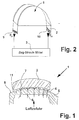
- the so called stretching die support surface 8 has a curved shape. This stretching die support surface 8 is bulged outward in the horizontal direction, it is intended to be Transfer contour to the metal sheet 2.
- the metal sheet 2 which (according to this illustration and also with an anticipation of later described method steps according to FIG. 3) in one (with the help a stretch-pull means 3 according to FIG. 2) biased at the edge of the sheet metal and in one on one Pre-bending level stretched condition.
- the stretching die 5 has several holes 4, which are arranged vertically exiting the stretching die support surface 8. Through this Bores 4 is in an intermediate space, the stretching die support surface 8 and Include sheet metal support surface 11, blown compressed air 6, within - through which localized (n) amount of compressed air - a (between) spatially spread air cushion 7 forms.
- a largely completely perforated stretch-forming support surface 8 with a largely uniform borehole architecture of the bores 4 is arranged below the sheet metal support surface 11. It is also noted that below this sheet metal support surface 11, only certain sub-areas of the stretching mold support surface 8 are provided with bores 4, thereby realizing a partial construction of the air cushion 7.
- an air cushion 7 with a sufficiently constant forming air pressure P 3 is to be built up, on which the metal sheet 2 floats during the forming.
- the bores 4 mentioned are realized with cylindrical or non-cylindrical boreholes, the hole axis of which is arranged perpendicular to the stretching die support surface 8.
- Which borehole geometry is considered appropriate is up to the individual case. It is taken into account that the borehole cross section of the non-cylindrical boreholes 4 on the stretching die support surface 8 is larger than that which is located at an entry point of the compressed air 6 vertically upstream of it into the individual borehole 4.
- a non-cylindrical borehole exit on the stretching die support surface 8 will at least enjoy the advantage of better cleaning of the bores 4.
- the compressed air source (not shown in the figure), from which the boreholes 4 are fed with compressed air 6, is arranged internally or externally of the drawing die 5 (depending on expediency). It is also added that the compressed air 6 will have a compressed air temperature of up to 350 degrees Celsius.
- the compressed air (which builds up the air cushion 7) is heated to this air temperature value and is later referred to as the heating temperature T 2 .
- This heated temperature value (the heating temperature T 2 ) is kept constant during the actual forming of the metal sheet 2, which can be achieved, for example, with a controllable heating source (not shown), which will pass the compressed air 6 (before it emerges at the stretching die support surface 8), implements.
- the metal sheet 2 consists of a material which is made, for example, of an aluminum alloy which can be formed at room temperature T 1 and which can be reshaped by the heating and consequent reduction in the yield stress during its loading.
- the material of the metal sheet 2 will mainly relate to a hardenable or non-hardenable aluminum alloy, which is largely used in aircraft construction.
- a process (described in more detail later) can be implemented with any metal (sheet 2), since almost all metals lose strength when heated.
- metal sheets 2 of a corresponding type will also be formed, which do not always have a flat appearance.
- the arrangement presented will also be able to form corresponding metal sheets 2, which are provided with an irregular surface curvature. Otherwise, these metal sheets 2 have a precisely specified surface curvature. In the worst case, the irregular appearance is understood to mean a creased sheet metal surface.
- FIG. 2 shows the arrangement 1 (presented with respect to FIG. 1) for shaping the metal sheet 2, which is expanded with a (indicated) stretch-pull means 3.
- the latter is required in order to fasten the side edges 9, 10 of the metal sheet 2 (lying horizontally on the stretching die support surface 8) on the output side of the (according to the example: convex) curvature.
- the stretch-drawing mold 5 will attack the metal sheet 2 on both sheet metal sides on these (opposing) side edges 9, 10 each with a tensile force F 21 or F 22 , provided that the metal sheet 2 is mechanically suitable on the edge of the stretch-pull means 3 in a suitable manner is attached.
- the individual side edge 9, 10 will be clamped between the clamping surfaces of a (vertically lowerable) clamping device, which is known under the name "clamping claw".
- a (vertically lowerable) clamping device which is known under the name "clamping claw”.
- FIG. 2 aims to explain stretch drawing in principle, it is further added that when the tensile forces F 21 , F 22 are applied, the metal sheet 2 is first subjected to stretching over the (horizontal) sheet length above the drawing die support surface 8, as a result of which on the metal sheet 2 (also supported by its stretching) the surface contour of the stretching die 5 is transferred.
- FIG. 3 shows a representation of (correlated) diagrams of the Forming process shown, which changes the air pressure, temperature and path illustrate time-dependent.
- the conventional metal sheet 2 is first positioned over the stretching die 5 and then placed on the curved die-drawing support surface 8. Then the side edges 9, 10 of the metal sheet 2 lying opposite one another in the horizontal plane are fastened, preferably clamped, to the tension-stretching means (3) at the edges of the stretch-drawing mold 5 [ie near the beginning of the convex-shaped curvature of the stretch-drawing mold support surface 8 curved in this way, and then pretensioned on its curved stretching mold support surface 8 under the action of room temperature T 1 and atmospheric ambient air pressure P 1 until a defined pretensioning time t 1 has elapsed, the metal sheet 2 as a result of the mechanical pretensioning on the side of the sheet metal from a rest position to the prebending level of a pretensioning path s 1 is stretched.
- This compressed air 6 will then spread between the stretching die support surface 8 and the sheet metal support surface 11, as a result of which an air cushion 7 is formed between these two support surfaces.
- the metal sheet (2) under tension will absorb the heat of the heating temperature (T 2 ), but will not experience any changes in the pre-bending level.
- the metal sheet 2 is clamped with a constant forming air pressure P 3 until a forming time t 3 has elapsed.
- the metal sheet 2 is moved in the horizontal direction of motion above the air cushion 7 so that it is almost frictionless, as a result of which the metal sheet (2), the sheet temperature of which is kept constant at the heating temperature (T 2 ).
- the sheet metal 2 will assume a (for example convex) curvature which is adapted to the surface contour of the drawing die 5 and which will change within the forming phase t 3 - t 2 will change iteratively to the forming level of a forming path s 2 .
- the shape-altered metal sheet 2 is cooled by a compressed air 6 cooled to the room temperature T 1 until a cooling time t 4 has elapsed, with a constant cooling air pressure which corresponds to the level of the heating pressure P 2 .
- This cooled compressed air is also passed through the bores 4 of the stretching die 5 to the shaped metal sheet 2, the shape-changing metal sheet 2 not experiencing any changes in the level of deformation during the cooling phase t 4 -t 3 .
- the side edges 9, 10 of the metal sheet 2, which are fixed at the edges, are prestressed on the stretching die support surface 8 under the action of room temperature T 1 and atmospheric ambient air pressure P 1 until a defined pretensioning time t 1 has elapsed, the metal sheet 2 being released due to the mechanical tensioning on the sheet metal side a rest position is stretched to the pre-bending level of a prestressing path s 1 . Only then is a tempered compressed air 6, which will reach a heating temperature T 2 after the expiry of a heating time t 2 , passed through the bores 4 of the stretching die 5 with a constant heating air pressure P 2 .
- this metal sheet 2 is calibrated [ie brought to an exact measure] under the action of room temperature T 1 until the end of a completion time t 5 , this metal sheet 2 during the calibration phase t 5 - t 4 will experience a change [of the forming level] to the calibration level of a calibration path s 3 .
- a surface pressure of up to 200 bar / cm 2 and an inflow of tempered compressed air 6 with a heating temperature T 2 of up to 350 ° C. are implemented
- the sheet-metal contact surface 11 will lift off from the stretch-drawing contact surface 8 at least during the forming phase t 3 -t 2 due to the air cushion 7 present.
Landscapes
- Engineering & Computer Science (AREA)
- Mechanical Engineering (AREA)
- Shaping Metal By Deep-Drawing, Or The Like (AREA)
- Blow-Moulding Or Thermoforming Of Plastics Or The Like (AREA)
- Manufacturing Of Printed Wiring (AREA)
- Shaping Of Tube Ends By Bending Or Straightening (AREA)
Abstract
Description
- Fig. 1
- eine Anordnung zum Umformen eines Metallbleches mit dessen Luftkissenauflage;
- Fig. 2
- die Anordnung zum Umformen eines Metallbleches und dessen mechanische Befestigung an einem Streck-Zug-Mittel;
- Fig. 3
- eine Darstellung von Diagrammen des Umformprozesses, welche die Luftdruck-, Temperatur-und Weg-Veränderungen zeitabhängig veranschaulichen.
Die nachfolgend angegebenen Schritte werden deutlich, sofern man die Angaben mit den Darstellungen der Diagramme vergleicht. Danach werden folgende Schritte verfahrensmäßig umgesetzt:
- 1
- Anordnung zum Umformen eines Metallbleches
- 2
- Metallblech
- 3
- Zug-Streck-Mittel
- 4
- Bohrung
- 5
- Streckziehform
- 6
- Druckluft
- 7
- Luftkissen
- 8
- Streckziehform-Auflagefläche
- 9
- Seitenrand (des Metallbleches 2)
- 10
- Seitenrand (des Metallbleches 2)
- 11
- Metallblech-Auflagefläche
- FZ1, FZ2
- Zugkraft
- P1
- atmosphärischer Umgebungsluftdruck
- P2
- Vorheizluftdruck
- P3
- Umformluftdruck
- T1
- Raumtemperatur
- T2
- Aufheiztemperatur
- t1
- Vorspannzeit
- t2
- Aufheizzeit
- t3
- Umformzeit
- t4
- Abkühlzeit
- t5
- Abschlusszeit
- t2 - t1
- Aufheizphase
- t3 - t2
- Umformphase
- t4 - t3
- Abkühlphase
- t5 - t4
- Kalibrierphase
- s1
- Vorspannweg
- s2
- Umformweg
- s3
- Kalibrierweg
Claims (16)
- Anordnung zum Umformen eines Metallbleches, mit einer Streckziehform (5) und einem Zug-Streck-Mittel (3), wobei das Metallblech (2) auf einer gekrümmten Streckziehform-Auflagefläche (8), die in horizontaler Richtung nach außen gewölbt ist, positioniert ist, deren ausgangsseitlich der Wölbung befindlichen Seitenränder (9, 10) dem Zug- Streck-Mittel (3) befestigt sind, dabei das Zug-Streck-Mittel (3) das Metallblech (2) zu beiden Blechseiten an den sich gegenüberstehenden Seitenrändern (9, 10) mit einer Zugkraft (FZ1, FZ2) angreifen wird und über dessen Blechlänge oberhalb der Streckziehform-Auflagefläche (8) das Metallblech (2) einer Steckung unterziehen wird, wodurch auf das Metallblech (2) auch unterstützt durch dessen Streckung die Oberflächenkontur der Streckziehform (5) übertragen wird,
dadurch gekennzeichnet, dass der Streckziehform (5) mehrere Bohrungen (4) äusgenommen sind, die vertikal austretend der Streckziehform-Auflagefläche (8) angeordnet sind, und oberhalb dieser Streckziehform-Auflagefläche (8) ein von einer Metallblech-Auflagefläche (11) eingeschlossenes Luftkissen (7) ausgebreitet ist, das von einer durch die Bohrungen (4) geleiteten Druckluft (6) aufgebaut wird. - Anordnung nach Anspruch 1, dadurch gekennzeichnet, dass unterhalb der Metallblech-Auflagefläche (11) eine weitestgehend vollständig perforierte Streckziehform-Auflagefläche (8) mit einer weitestgehend einheitlichen Bohrloch-Architektur der Bohrungen (4) angeordnet ist.
- Anordnung nach den Ansprüchen 1 bis 2, dadurch gekennzeichnet, dass unterhalb der Metallblech-Auflagefläche (11) nur bestimmte Teilbereiche der Streckziehform-Auflagefläche (8) mit Bohrungen (4) ausgestattet sind und dadurch ein partieller Aufbau des Luftkissens (7) realisiert ist.
- Anordnung nach Anspruch 1, dadurch gekennzeichnet, dass die Bohrungen (4) mit zylindrischen oder nicht zylindrischen Bohrlöchern realisiert sind, deren Lochachse lotrecht zur Streckziehform-Auflagefläche (8) angeordnet ist.
- Anordnung nach Anspruch 4, dadurch gekennzeichnet, dass der Bohrloch-Querschnitt der nicht zylindrischen Bohrlöchern an der Streckziehform-Auflagefläche (8) größer demjenigen ist, der an einer ihm vertikal vorgeordneten Eintrittsstelle der Druckluft (6) in die einzelne Bohrung (4) gelegen ist.
- Anordnung nach Anspruch 1, dadurch gekennzeichnet, dass in- oder extern der Streckziehform (5) einer Druckluftquelle angeordnet ist, von der aus durch die Bohrungen (4) eine Druckluft (6) geleitet wird.
- Anordnung nach Anspruch 1, dadurch gekennzeichnet, dass eine Lufttemperatur der Druckluft (6), mit der das Luftkissens (7) aufgebaut wird, von bis zu 350 Grad Celsius vorhanden ist.
- Anordnung nach Anspruch 1, dadurch gekennzeichnet, dass der Werkstoff des Metallblechs (2) in der Hauptsache eine aushärtbare oder nicht aushärtbare Aluminium-Legierung ist.
- Anordnung nach Anspruch 1, dadurch gekennzeichnet, dass das Metallblech (2) mit einer regellosen oder genau spezifizierten Oberfläche oder mit ebenflächiger Oberfläche versehen ist, die weitestgehend der Oberflächenkontur der Streckziehform-Auflagefläche (8) angepasst ist.
- Verfahren zum Umformen eines Metallbleches mit einer Anordnung nach Anspruch 1, bei dem das Metallblech (2) einer Streck-Zieh-Prozedur unterzogen wird, um eine einfach oder doppelt gekrümmte und konvexe oder konkave Wölbung auf das Metallblech (2) zu übertragen,
gekennzeichnet durch folgende Schritte:a) es wird ein Metallblech (2) über der Streckziehform (5) positioniert und danach auf der gekrümmten Streckziehform-Auflagefläche (8) abgelegt,b) daraufhin werden die in horizontaler Ebene sich gegenüberliegenden Seitenränder (9, 10) des Metallblechs (2) randseitlich der Streckziehform (5) dem Zug-Streck-Mittel (3) befestigt und danach auf dessen gekrümmten Streckziehform-Auflagefläche (8) bei Einwirkung von Raumtemperatur (T1) und atmosphärischem Umgebungsluftdruck (P1) bis zum Ablauf von einer definierten Vorspannzeit (t1) vorgespannt, wobei das Metallblech (2) infolge der blechrandseitlichen mechanischen Vorspannung aus einer Ruhelage auf das Vorbiegeniveau eines Vorspannweges (s1) gestreckt wird,c) dann wird über die Bohrungen (4) der Streckziehform (5) mit einem konstanten Aufheizluftdruck (P2) eine temperierte Druckluft (6), die nach dem Ablauf einer Aufheizzeit (t2) eine Aufheiztemperatur (T2) erreichen wird, geleitet, welche sich danach zwischen der Streckziehform-Auflagefläche (8) und der Metallblech-Auflagefläche (11) ausbreiten wird, wodurch zwischen diesen beiden Auflageflächen ein Luftkissen (7) gebildet wird, wobei während der Aufheizphase (t2 - t1) das unter Vorspannung befindliche Metallblech (2) die Wärme der Aufheiztemperatur (T2) aufnehmen wird, aber keine Veränderungen des Vorbiegeniveaus erfahren wird,d) dann werden die gegenüberliegenden Seitenränder des Metallblechs (2) bis zum Ablauf einer Umformzeit (t3) mit einem konstanten Umformluftdruck (P3) gespannt, gleichzeitig wird das Metallblech (2) mit Horizontalbewegungsrichtung über dem Luftkissen (7) schwebend nahezu reibungsfrei bewegt, wodurch das Metallblech (2), dessen Blechtemperatur auf Aufheiztemperatur (T2) konstant gehalten wird, infolge der Blechbewegung nach dem Ablauf der Umformzeit (t3) [durch dessen randseitlichen Zugbelastung mit nachfolgender Streckung des Metallblech-Profils) eine der Oberflächenkontur der Streckziehform (5) angepasste Wölbung annehmen wird, die sich innerhalb der Umformphase (t3 - t2) iterativ auf das Umformniveau eines Umformweg (s2) verändern wird,e) dann wird das dermaßen formveränderte Metallblech (2) durch eine bis zum Ablauf einer Abkühlzeit (t4) auf die Raumtemperatur (T1) abgekühlte Druckluft (6) mit einen konstanten Abkühlluftdruck, der dem Niveau des Aufheizdruckes (P2) entspricht, abgekühlt, die ebenfalls über die Bohrungen (4) der Streckziehform (5) an das geformte Metallblech (2) geführt wird, wobei das formveränderte Metallblech (2) während der Abkühlphase (t4 - t3) keine Veränderungen des Umformniveaus erfahren wird. - Verfahren zum Umformen eines Metallbleches mit einer Anordnung nach Anspruch 1, bei dem das Metallblech (2) einer Streck-Zieh-Prozedur unterzogen wird, um eine einfach oder doppelt gekrümmte und konvexe oder konkave Wölbung auf das Metallblech (2) zu übertragen,
gekennzeichnet durch folgende Schritte:a) zunächst werden die in horizontaler Ebene sich gegenüberliegenden Seitenränder (9, 10) des Metallblechs (2) randseitlich der Streckziehform (5) dem Zug-Streck-Mittel (3) befestigt und darauffolgend das randseitlich befestigte Metallblech (2) über der Streckziehform (5) positioniert, das anschließend vertikal soweit abgesenkt wird, bis das es auf der gekrümmten Streckziehform-Auflagefläche (8) abgelegt wird,b) daraufhin werden die randseitlich befestigten Seitenränder (9, 10) des Metallblechs (2) auf der Streckziehform-Auflagefläche (8) bei Einwirkung von Raumtemperatur (T1) und atmosphärischem Umgebungsluftdruck (P1) bis zum Ablauf von einer definierten Vorspannzeit (t1) vorgespannt, wobei das Metallblech (2) infolge der blechrandseitlichen mechanischen Vorspannung aus einer Ruhelage auf das Vorbiegeniveau eines Vorspannweges (s1) gestreckt wird,c) dann wird über die Bohrungen (4) der Streckziehform (5) mit einem konstanten Aufheizluftdruck (P2) eine temperierte Druckluft (6), die nach dem Ablauf einer Aufheizzeit (t2) eine Aufheiztemperatur (T2) erreichen wird, geleitet, welche sich danach zwischen der Streckziehform-Auflagefläche (8) und der Metallblech-Auflagefläche (11) ausbreiten wird, wodurch zwischen diesen beiden Auflageflächen ein Luftkissen (7) gebildet wird, wobei während der Aufheizphase (t2 - t1) das unter Vorspannung befindliche Metallblech (2) die Wärme der Aufheiztemperatur (T2) aufnehmen wird, aber keine Veränderungen des Vorbiegeniveaus erfahren wird,d) dann werden die gegenüberliegenden Seitenränder des Metallblechs (2) bis zum Ablauf einer Umformzeit (t3) mit einem konstanten Umformluftdruck (P3) gespannt, gleichzeitig wird das Metallblech (2) mit Horizontalbewegungsrichtung über dem Luftkissen (7) schwebend nahezu reibungsfrei bewegt, wodurch das Metallblech (2), dessen Blechtemperatur auf Aufheiztemperatur (T2) konstant gehalten wird, infolge der Blechbewegung nach dem Ablauf der Umformzeit (t3) [durch dessen randseillichen Zugbelastung mit nachfolgender Streckung des Metallblech-Profils) eine der Oberflächenkontur der Streckziehform (5) angepasste Wölbung annehmen wird, die sich innerhalb der Umformphase (t3 - t2) iterativ auf das Umformniveau eines Umformweg (s2) verändern wird,e) dann wird das dermaßen formveränderte Metallblech (2) durch eine bis zum Ablauf einer Abkühlzeit (t4) auf die Raumtemperatur (T1) abgekühlte Druckluft (6) mit einen konstanten Abkühlluftdruck, der dem Niveau des Aufheizdruckes (P2) entspricht, abgekühlt, die ebenfalls über die Bohrungen (4) der Streckziehform (5) an das geformte Metallblech (2) geführt wird, wobei das formveränderte Metallblech (2) während der Abkühlphase (t4 - t3) keine Veränderungen des Umformniveaus erfahren wird. - Verfahren zum Umformen einer Metallbleches nach den Ansprüchen 10 oder 11,
dadurch gekennzeichnet, dass nachfolgend dem Schritt e) das im abkühlten Zustand befindliche vorveränderte Metallblech (2) bei Einwirkung von Raumtemperatur (T1) bis zum Ablauf einer Abschlusszeit (t5) kalibriert [auf genaues Maß bringen] wird, wobei dieses Metallblech (2) während der Kalibrierphase (t5 - t4) eine Veränderung [des Umformniveaus] auf das Kalibrierniveau eines Kalibrierweges (s3) erfahren wird. - Verfahren zum Umformen einer Metallbleches nach den Ansprüchen 10 oder 121,
dadurch gekennzeichnet, dass die gegenüberliegenden Seitenränder (9, 10) des Metallbleches (2) nahe dem Beginn der Wölbung der gekrümmten Streckziehform-Auflagefläche (8) dem Zug-Streck-Mittel (3) befestigt werden. - Verfahren zum Umformen eines Metallbleches nach Anspruch 13,
dadurch gekennzeichnet, dass der betreffende Seitenrand (9, 10) des Metallbleches (2) einem in vertikaler Richtung positionsveränderlichen Greifmittel des Zug-Streck-Mittels (3) eingespannt wird. - Verfahren zum Umformen einer Metallbleches nach den Ansprüchen 10 oder 11,
dadurch gekennzeichnet, dass während der Umformphase (t3 - t2) eine Flächenpressung von bis zu 200 bar und ein Zustrom von temperierter Druckluft (6) mit einer Aufheiztemperatur (T2) von bis zu 350 °C umgesetzt wird. - Verfahren zum Umformen eines Metallbleches nach den Ansprüchen 10 oder 11,
dadurch gekennzeichnet, dass die Metallblech-Auflagefläche (11) wenigstens während der Umformphase (t3 - t2) von der Streckziehform-Auflagefläche (8) infolge des vorhandenen Luftkissens (7) abheben wird.
Applications Claiming Priority (2)
| Application Number | Priority Date | Filing Date | Title |
|---|---|---|---|
| DE10063287A DE10063287B4 (de) | 2000-12-19 | 2000-12-19 | Verfahren zum Umformen eines Metallbleches |
| DE10063287 | 2000-12-19 |
Publications (2)
| Publication Number | Publication Date |
|---|---|
| EP1216768A1 true EP1216768A1 (de) | 2002-06-26 |
| EP1216768B1 EP1216768B1 (de) | 2004-06-09 |
Family
ID=7667784
Family Applications (1)
| Application Number | Title | Priority Date | Filing Date |
|---|---|---|---|
| EP01127928A Expired - Lifetime EP1216768B1 (de) | 2000-12-19 | 2001-11-23 | Anordnung und Verfahren zum Umformen eines Metallbleches |
Country Status (7)
| Country | Link |
|---|---|
| US (1) | US6619094B2 (de) |
| EP (1) | EP1216768B1 (de) |
| AT (1) | ATE268655T1 (de) |
| CA (1) | CA2365771C (de) |
| DE (2) | DE10063287B4 (de) |
| ES (1) | ES2222302T3 (de) |
| TR (1) | TR200402020T4 (de) |
Cited By (1)
| Publication number | Priority date | Publication date | Assignee | Title |
|---|---|---|---|---|
| WO2017080841A1 (en) | 2015-11-13 | 2017-05-18 | Aleris Rolled Products Germany Gmbh | Method of manufacturing a fibre metal laminate material |
Families Citing this family (47)
| Publication number | Priority date | Publication date | Assignee | Title |
|---|---|---|---|---|
| US6799450B2 (en) * | 2002-10-11 | 2004-10-05 | General Motors Corporation | Method of stretch forming an aluminum metal sheet and handling equipment for doing the same |
| BRPI0408432B1 (pt) * | 2003-03-17 | 2015-07-21 | Corus Aluminium Walzprod Gmbh | Método para produção de uma estrutura integrada de alumínio monolítico e produto de alumínio usinado daquela estrutura |
| US20050005664A1 (en) * | 2003-07-09 | 2005-01-13 | Wesley Scott | System and method for bending strip material to create cutting dies |
| JP3863874B2 (ja) * | 2003-10-02 | 2006-12-27 | 新日本製鐵株式会社 | 金属板材の熱間プレス成形装置及び熱間プレス成形方法 |
| DE10346661B4 (de) * | 2003-10-08 | 2006-10-12 | Ise Innomotive Systems Europe Gmbh | Verfahren zur Warmumformung von Blechplatinen sowie Vorrichtung zur Durchführung des Verfahrens |
| US7086268B2 (en) * | 2004-03-16 | 2006-08-08 | Ford Global Technologies, Llc | Apparatus and method for removing and cooling a part from a forming tool |
| US20070261462A1 (en) * | 2006-05-11 | 2007-11-15 | Rti International Metals, Inc. | Method and apparatus for creep forming of and relieving stress in an elongated metal bar |
| US20070261463A1 (en) * | 2006-05-11 | 2007-11-15 | Rti International Metals, Inc. | Method and apparatus for creep forming of and relieving stress in an elongated metal bar |
| US20070261461A1 (en) * | 2006-05-11 | 2007-11-15 | Rti International Metals, Inc. | Method and apparatus for hot forming elongated metallic bars |
| US8069547B2 (en) * | 2008-03-05 | 2011-12-06 | Victaulic Company | Installation-ready pipe coupling method of manufacture |
| US8282136B2 (en) | 2008-06-30 | 2012-10-09 | Mueller International, Llc | Slip on groove coupling with multiple sealing gasket |
| US8567226B2 (en) * | 2008-10-06 | 2013-10-29 | GM Global Technology Operations LLC | Die for use in sheet metal forming processes |
| US8671729B2 (en) * | 2010-03-02 | 2014-03-18 | GM Global Technology Operations LLC | Fluid-assisted non-isothermal stamping of a sheet blank |
| USD706200S1 (en) | 2010-09-22 | 2014-06-03 | Pylon Manufacturing Corporation | Windshield wiper cover |
| US9174609B2 (en) | 2011-04-21 | 2015-11-03 | Pylon Manufacturing Corp. | Wiper blade with cover |
| US9457768B2 (en) | 2011-04-21 | 2016-10-04 | Pylon Manufacturing Corp. | Vortex damping wiper blade |
| WO2013016493A1 (en) | 2011-07-28 | 2013-01-31 | Pylon Manufacturing Corp. | Windshield wiper adapter, connector and assembly |
| US8806700B2 (en) | 2011-07-29 | 2014-08-19 | Pylon Manufacturing Corporation | Wiper blade connector |
| WO2013019645A1 (en) | 2011-07-29 | 2013-02-07 | Pylon Manufacturing Corp. | Windshield wiper connector |
| US9108595B2 (en) | 2011-07-29 | 2015-08-18 | Pylon Manufacturing Corporation | Windshield wiper connector |
| US9162276B2 (en) * | 2011-10-14 | 2015-10-20 | Bell Helicopter Textron Inc. | System and method of manufacturing a structure |
| USD696751S1 (en) | 2011-10-27 | 2013-12-31 | Mueller International, Llc | Slip-on gasket |
| USD680629S1 (en) | 2011-11-21 | 2013-04-23 | Mueller International, Llc | Slip-on coupling segment |
| USD680630S1 (en) | 2011-11-21 | 2013-04-23 | Mueller International, Llc | Slip-on coupling assembly |
| US9194516B2 (en) | 2012-01-20 | 2015-11-24 | Mueller International, Llc | Slip-on coupling |
| US9500307B2 (en) | 2012-01-20 | 2016-11-22 | Mueller International, Llc | Slip-on coupling gasket |
| US9039046B2 (en) | 2012-01-20 | 2015-05-26 | Mueller International, Llc | Coupling with tongue and groove |
| US9534715B2 (en) | 2012-01-20 | 2017-01-03 | Mueller International, Llc | Coupling gasket with multiple sealing surfaces |
| US20130219649A1 (en) | 2012-02-24 | 2013-08-29 | Pylon Manufacturing Corp. | Wiper blade |
| US10723322B2 (en) | 2012-02-24 | 2020-07-28 | Pylon Manufacturing Corp. | Wiper blade with cover |
| CA2865292C (en) | 2012-02-24 | 2018-03-13 | Pylon Manufacturing Corp. | Wiper blade |
| US10829092B2 (en) | 2012-09-24 | 2020-11-10 | Pylon Manufacturing Corp. | Wiper blade with modular mounting base |
| US9168585B2 (en) | 2012-11-02 | 2015-10-27 | Mueller International, Llc | Coupling with extending parting line |
| US10166951B2 (en) | 2013-03-15 | 2019-01-01 | Pylon Manufacturing Corp. | Windshield wiper connector |
| US9505380B2 (en) | 2014-03-07 | 2016-11-29 | Pylon Manufacturing Corp. | Windshield wiper connector and assembly |
| USD787308S1 (en) | 2014-10-03 | 2017-05-23 | Pylon Manufacturing Corp. | Wiper blade package |
| USD777079S1 (en) | 2014-10-03 | 2017-01-24 | Pylon Manufacturing Corp. | Wiper blade frame |
| US10363905B2 (en) | 2015-10-26 | 2019-07-30 | Pylon Manufacturing Corp. | Wiper blade |
| CN109311451B (zh) | 2016-05-19 | 2022-08-23 | 电缆塔制造有限公司 | 挡风玻璃雨刮器片 |
| WO2017201458A1 (en) | 2016-05-19 | 2017-11-23 | Pylon Manufacturing Corp. | Windshield wiper connector |
| AU2017268008A1 (en) | 2016-05-19 | 2018-11-22 | Pylon Manufacturing Corp. | Windshield wiper connector |
| US11040705B2 (en) | 2016-05-19 | 2021-06-22 | Pylon Manufacturing Corp. | Windshield wiper connector |
| WO2017201485A1 (en) | 2016-05-19 | 2017-11-23 | Pylon Manufacturing Corp. | Windshield wiper connector |
| CN114683000B (zh) * | 2021-05-27 | 2023-11-17 | 江苏瑞吉达建材科技有限公司 | 一种耐蚀双曲率铝合金板制备方法 |
| DE102021126237B3 (de) | 2021-10-11 | 2023-02-02 | Schaeffler Technologies AG & Co. KG | Bipolarplatte einer Brennstoffzelle und Verfahren zur Herstellung und Detektion geometrischer Merkmale eines Halbblechs einer Bipolarplatte |
| WO2023089358A1 (en) * | 2021-11-18 | 2023-05-25 | Arcelormittal | Hot stamping die and hot stamping process using a hot stamping press |
| CN115069910B (zh) * | 2022-06-29 | 2025-03-11 | 江门市恒正自动化设备科技有限公司 | 一种包底片加工设备 |
Citations (3)
| Publication number | Priority date | Publication date | Assignee | Title |
|---|---|---|---|---|
| GB543040A (en) * | 1940-10-25 | 1942-02-06 | Standard Pressed Steel Co | Improvements in or relating to the forming by stretching of sheet metal particularly aluminium and aluminium alloy sheet |
| US2808501A (en) * | 1955-11-25 | 1957-10-01 | Lockheed Aircraft Corp | Apparatus and improvements for hot forming materials |
| US6063216A (en) * | 1997-08-15 | 2000-05-16 | Trico Products Corporation | Working of a metallic strip |
Family Cites Families (5)
| Publication number | Priority date | Publication date | Assignee | Title |
|---|---|---|---|---|
| DE749725C (de) | 1941-10-24 | 1944-12-02 | Formklotz zum Streckziehen | |
| US2737224A (en) * | 1951-12-10 | 1956-03-06 | Boeing Co | Apparatus for forming sheet metal |
| US2752982A (en) * | 1952-05-15 | 1956-07-03 | Romeo A Lalli | Device for stretch forming metal sheets, and having a sheet metal die |
| US2952294A (en) * | 1957-05-28 | 1960-09-13 | Nat Res Dev | Forming of sheet metal |
| FR1224629A (fr) * | 1959-05-19 | 1960-06-24 | Flugzeugwerke Dresden Veb | Procédé et dispositif de façonnage sans formation de copeaux |
-
2000
- 2000-12-19 DE DE10063287A patent/DE10063287B4/de not_active Expired - Fee Related
-
2001
- 2001-11-23 DE DE50102528T patent/DE50102528D1/de not_active Expired - Lifetime
- 2001-11-23 EP EP01127928A patent/EP1216768B1/de not_active Expired - Lifetime
- 2001-11-23 TR TR2004/02020T patent/TR200402020T4/xx unknown
- 2001-11-23 AT AT01127928T patent/ATE268655T1/de active
- 2001-11-23 ES ES01127928T patent/ES2222302T3/es not_active Expired - Lifetime
- 2001-12-19 CA CA002365771A patent/CA2365771C/en not_active Expired - Fee Related
- 2001-12-19 US US10/029,422 patent/US6619094B2/en not_active Expired - Fee Related
Patent Citations (3)
| Publication number | Priority date | Publication date | Assignee | Title |
|---|---|---|---|---|
| GB543040A (en) * | 1940-10-25 | 1942-02-06 | Standard Pressed Steel Co | Improvements in or relating to the forming by stretching of sheet metal particularly aluminium and aluminium alloy sheet |
| US2808501A (en) * | 1955-11-25 | 1957-10-01 | Lockheed Aircraft Corp | Apparatus and improvements for hot forming materials |
| US6063216A (en) * | 1997-08-15 | 2000-05-16 | Trico Products Corporation | Working of a metallic strip |
Cited By (2)
| Publication number | Priority date | Publication date | Assignee | Title |
|---|---|---|---|---|
| WO2017080841A1 (en) | 2015-11-13 | 2017-05-18 | Aleris Rolled Products Germany Gmbh | Method of manufacturing a fibre metal laminate material |
| DE112016005215T5 (de) | 2015-11-13 | 2018-08-02 | Aleris Rolled Products Germany Gmbh | Verfahren zur Herstellung eines Faser-Metall-Laminat-Materials |
Also Published As
| Publication number | Publication date |
|---|---|
| US20020095967A1 (en) | 2002-07-25 |
| DE10063287A1 (de) | 2002-07-04 |
| ATE268655T1 (de) | 2004-06-15 |
| ES2222302T3 (es) | 2005-02-01 |
| EP1216768B1 (de) | 2004-06-09 |
| DE50102528D1 (de) | 2004-07-15 |
| CA2365771C (en) | 2008-09-23 |
| CA2365771A1 (en) | 2002-06-19 |
| DE10063287B4 (de) | 2007-05-03 |
| TR200402020T4 (tr) | 2004-09-21 |
| US6619094B2 (en) | 2003-09-16 |
Similar Documents
| Publication | Publication Date | Title |
|---|---|---|
| EP1216768B1 (de) | Anordnung und Verfahren zum Umformen eines Metallbleches | |
| DE10326554B4 (de) | Verfahren zum Herstellen einer Stossstangenverstärkung | |
| DE102019132170B4 (de) | Nietstruktur für eine dünne kühlkörperrippe und eine dünne abdeckplatte | |
| EP2155917A1 (de) | Verfahren zur herstellung eines lokal gehärteten profilbauteils, lokal gehärtetes profilbauteil und verwendung eines lokal gehärteten profilbauteils | |
| EP2701862B1 (de) | Verfahren und vorrichtung zur herstellung flanschbehafteter ziehteile mit gleichzeitigem beschnitt | |
| DE202020105963U1 (de) | Kraftfahrzeugbauteil | |
| DE60016709T2 (de) | Verfahren und vorrichtung zum ausweiten eines rohrmaterials | |
| DE69807723T2 (de) | Vorrichtung zum klemmen, führen und fördern der ränder einer mit schnitten versehenen folienbahn in einer maschine zum herstellen von streckmetall | |
| DE10303184B3 (de) | Verfahren und Vorrichtung zur Herstellung von einer in ihrer Dicke mindestens in einem Bereich variierenden Platine | |
| DE102005057424B4 (de) | Verfahren und Vorrichtung zum kernlosen Einformen von Hohlprofilen | |
| EP0546319A1 (de) | Streckbiegeverfahren zur Biegung von Hohlprofilen und Profildorn-Streckbiegemaschine | |
| EP0882639B1 (de) | Karosserierahmenbauteil für die Karosserie eines Kraftfahrzeuges und Verfahren für dessen Herstellung | |
| EP1467114A1 (de) | Verbindungselement | |
| EP1975293A1 (de) | Litzentragschiene aus gebogenem Blech | |
| DE102022104206A1 (de) | Pressgehärtetes Blechformteil mit unterschiedlichen Blechdicken und Festigkeiten | |
| EP0979693B1 (de) | Verfahren zur Herstellung eines Dichtkanals für eine Tür- oder Heckklappenöffnung | |
| DE19939860A1 (de) | Verfahren zur Verbesserung der Planheit von Blechen | |
| DE102014115073A1 (de) | Verfahren und Vorrichtung zur Herstellung eines Kragens an einem Werkstück | |
| DE69000714T2 (de) | Vorrichtung zum biegen und haerten einer glasscheibe. | |
| DE19744787A1 (de) | Stanzniet sowie Verfahren zu dessen Herstellung | |
| DE1627701A1 (de) | Verfahren zum schrittweisen Schmieden von mehrhuebigen Kurbelwellen | |
| DE102005036526B4 (de) | Verfahren zur Herstellung eines einteiligen, hinteren Querträgers für Sitzrahmen von Fahrzeugsitzen | |
| DE10043880A1 (de) | Stossfänger | |
| DE102014203767A1 (de) | Verfahren zur Herstellung von Fahrzeugbauteilen | |
| EP2805781A2 (de) | Hohlprofil für eine Trägerstruktur eines Fahrzeugs |
Legal Events
| Date | Code | Title | Description |
|---|---|---|---|
| PUAI | Public reference made under article 153(3) epc to a published international application that has entered the european phase |
Free format text: ORIGINAL CODE: 0009012 |
|
| AK | Designated contracting states |
Kind code of ref document: A1 Designated state(s): AT BE CH CY DE DK ES FI FR GB GR IE IT LI LU MC NL PT SE TR |
|
| AX | Request for extension of the european patent |
Free format text: AL;LT;LV;MK;RO;SI |
|
| 17P | Request for examination filed |
Effective date: 20021227 |
|
| AKX | Designation fees paid |
Designated state(s): AT BE CH CY DE DK ES FI FR GB GR IE IT LI LU MC NL PT SE TR |
|
| GRAP | Despatch of communication of intention to grant a patent |
Free format text: ORIGINAL CODE: EPIDOSNIGR1 |
|
| GRAS | Grant fee paid |
Free format text: ORIGINAL CODE: EPIDOSNIGR3 |
|
| GRAA | (expected) grant |
Free format text: ORIGINAL CODE: 0009210 |
|
| AK | Designated contracting states |
Kind code of ref document: B1 Designated state(s): AT BE CH CY DE DK ES FI FR GB GR IE IT LI LU MC NL PT SE TR |
|
| PG25 | Lapsed in a contracting state [announced via postgrant information from national office to epo] |
Ref country code: FI Free format text: LAPSE BECAUSE OF FAILURE TO SUBMIT A TRANSLATION OF THE DESCRIPTION OR TO PAY THE FEE WITHIN THE PRESCRIBED TIME-LIMIT Effective date: 20040609 Ref country code: IE Free format text: LAPSE BECAUSE OF FAILURE TO SUBMIT A TRANSLATION OF THE DESCRIPTION OR TO PAY THE FEE WITHIN THE PRESCRIBED TIME-LIMIT Effective date: 20040609 Ref country code: CY Free format text: LAPSE BECAUSE OF FAILURE TO SUBMIT A TRANSLATION OF THE DESCRIPTION OR TO PAY THE FEE WITHIN THE PRESCRIBED TIME-LIMIT Effective date: 20040609 |
|
| REG | Reference to a national code |
Ref country code: GB Ref legal event code: FG4D Free format text: NOT ENGLISH |
|
| REG | Reference to a national code |
Ref country code: CH Ref legal event code: EP |
|
| REF | Corresponds to: |
Ref document number: 50102528 Country of ref document: DE Date of ref document: 20040715 Kind code of ref document: P |
|
| REG | Reference to a national code |
Ref country code: IE Ref legal event code: FG4D Free format text: GERMAN |
|
| PG25 | Lapsed in a contracting state [announced via postgrant information from national office to epo] |
Ref country code: DK Free format text: LAPSE BECAUSE OF FAILURE TO SUBMIT A TRANSLATION OF THE DESCRIPTION OR TO PAY THE FEE WITHIN THE PRESCRIBED TIME-LIMIT Effective date: 20040909 Ref country code: GR Free format text: LAPSE BECAUSE OF FAILURE TO SUBMIT A TRANSLATION OF THE DESCRIPTION OR TO PAY THE FEE WITHIN THE PRESCRIBED TIME-LIMIT Effective date: 20040909 |
|
| REG | Reference to a national code |
Ref country code: SE Ref legal event code: TRGR |
|
| GBT | Gb: translation of ep patent filed (gb section 77(6)(a)/1977) |
Effective date: 20040922 |
|
| PG25 | Lapsed in a contracting state [announced via postgrant information from national office to epo] |
Ref country code: LU Free format text: LAPSE BECAUSE OF NON-PAYMENT OF DUE FEES Effective date: 20041123 |
|
| PG25 | Lapsed in a contracting state [announced via postgrant information from national office to epo] |
Ref country code: MC Free format text: LAPSE BECAUSE OF NON-PAYMENT OF DUE FEES Effective date: 20041130 |
|
| REG | Reference to a national code |
Ref country code: IE Ref legal event code: FD4D |
|
| REG | Reference to a national code |
Ref country code: ES Ref legal event code: FG2A Ref document number: 2222302 Country of ref document: ES Kind code of ref document: T3 |
|
| ET | Fr: translation filed | ||
| PLBE | No opposition filed within time limit |
Free format text: ORIGINAL CODE: 0009261 |
|
| STAA | Information on the status of an ep patent application or granted ep patent |
Free format text: STATUS: NO OPPOSITION FILED WITHIN TIME LIMIT |
|
| 26N | No opposition filed |
Effective date: 20050310 |
|
| PG25 | Lapsed in a contracting state [announced via postgrant information from national office to epo] |
Ref country code: LI Free format text: LAPSE BECAUSE OF NON-PAYMENT OF DUE FEES Effective date: 20051130 Ref country code: CH Free format text: LAPSE BECAUSE OF NON-PAYMENT OF DUE FEES Effective date: 20051130 |
|
| REG | Reference to a national code |
Ref country code: CH Ref legal event code: PL |
|
| PG25 | Lapsed in a contracting state [announced via postgrant information from national office to epo] |
Ref country code: PT Free format text: LAPSE BECAUSE OF NON-PAYMENT OF DUE FEES Effective date: 20041109 |
|
| REG | Reference to a national code |
Ref country code: ES Ref legal event code: PC2A Owner name: AIRBUS OPERATIONS GMBH Effective date: 20110930 |
|
| REG | Reference to a national code |
Ref country code: FR Ref legal event code: CD Owner name: AIRBUS OPERATIONS GMBH Effective date: 20111118 |
|
| PGFP | Annual fee paid to national office [announced via postgrant information from national office to epo] |
Ref country code: DE Payment date: 20121121 Year of fee payment: 12 Ref country code: FR Payment date: 20121130 Year of fee payment: 12 |
|
| PGFP | Annual fee paid to national office [announced via postgrant information from national office to epo] |
Ref country code: SE Payment date: 20121120 Year of fee payment: 12 Ref country code: IT Payment date: 20121127 Year of fee payment: 12 Ref country code: ES Payment date: 20121127 Year of fee payment: 12 Ref country code: GB Payment date: 20121120 Year of fee payment: 12 Ref country code: BE Payment date: 20121122 Year of fee payment: 12 |
|
| PGFP | Annual fee paid to national office [announced via postgrant information from national office to epo] |
Ref country code: NL Payment date: 20121120 Year of fee payment: 12 Ref country code: AT Payment date: 20121113 Year of fee payment: 12 |
|
| PGFP | Annual fee paid to national office [announced via postgrant information from national office to epo] |
Ref country code: TR Payment date: 20131025 Year of fee payment: 13 |
|
| BERE | Be: lapsed |
Owner name: *AIRBUS DEUTSCHLAND G.M.B.H. Effective date: 20131130 |
|
| REG | Reference to a national code |
Ref country code: DE Ref legal event code: R119 Ref document number: 50102528 Country of ref document: DE |
|
| REG | Reference to a national code |
Ref country code: NL Ref legal event code: V1 Effective date: 20140601 |
|
| REG | Reference to a national code |
Ref country code: SE Ref legal event code: EUG |
|
| REG | Reference to a national code |
Ref country code: AT Ref legal event code: MM01 Ref document number: 268655 Country of ref document: AT Kind code of ref document: T Effective date: 20131123 |
|
| GBPC | Gb: european patent ceased through non-payment of renewal fee |
Effective date: 20131123 |
|
| REG | Reference to a national code |
Ref country code: FR Ref legal event code: ST Effective date: 20140731 |
|
| PG25 | Lapsed in a contracting state [announced via postgrant information from national office to epo] |
Ref country code: SE Free format text: LAPSE BECAUSE OF NON-PAYMENT OF DUE FEES Effective date: 20131124 Ref country code: NL Free format text: LAPSE BECAUSE OF NON-PAYMENT OF DUE FEES Effective date: 20140601 Ref country code: DE Free format text: LAPSE BECAUSE OF NON-PAYMENT OF DUE FEES Effective date: 20140603 Ref country code: AT Free format text: LAPSE BECAUSE OF NON-PAYMENT OF DUE FEES Effective date: 20131123 Ref country code: IT Free format text: LAPSE BECAUSE OF NON-PAYMENT OF DUE FEES Effective date: 20131123 |
|
| REG | Reference to a national code |
Ref country code: DE Ref legal event code: R119 Ref document number: 50102528 Country of ref document: DE Effective date: 20140603 |
|
| PG25 | Lapsed in a contracting state [announced via postgrant information from national office to epo] |
Ref country code: BE Free format text: LAPSE BECAUSE OF NON-PAYMENT OF DUE FEES Effective date: 20131130 |
|
| PG25 | Lapsed in a contracting state [announced via postgrant information from national office to epo] |
Ref country code: GB Free format text: LAPSE BECAUSE OF NON-PAYMENT OF DUE FEES Effective date: 20131123 Ref country code: FR Free format text: LAPSE BECAUSE OF NON-PAYMENT OF DUE FEES Effective date: 20131202 |
|
| REG | Reference to a national code |
Ref country code: ES Ref legal event code: FD2A Effective date: 20150401 |
|
| PG25 | Lapsed in a contracting state [announced via postgrant information from national office to epo] |
Ref country code: ES Free format text: LAPSE BECAUSE OF NON-PAYMENT OF DUE FEES Effective date: 20131124 |
|
| PG25 | Lapsed in a contracting state [announced via postgrant information from national office to epo] |
Ref country code: TR Free format text: LAPSE BECAUSE OF NON-PAYMENT OF DUE FEES Effective date: 20141123 |