EP1216632A2 - Verstellbare Armlehne - Google Patents
Verstellbare Armlehne Download PDFInfo
- Publication number
- EP1216632A2 EP1216632A2 EP01204671A EP01204671A EP1216632A2 EP 1216632 A2 EP1216632 A2 EP 1216632A2 EP 01204671 A EP01204671 A EP 01204671A EP 01204671 A EP01204671 A EP 01204671A EP 1216632 A2 EP1216632 A2 EP 1216632A2
- Authority
- EP
- European Patent Office
- Prior art keywords
- armrest
- rail
- pedestal
- disposed
- pivotal
- Prior art date
- Legal status (The legal status is an assumption and is not a legal conclusion. Google has not performed a legal analysis and makes no representation as to the accuracy of the status listed.)
- Withdrawn
Links
- NJPPVKZQTLUDBO-UHFFFAOYSA-N novaluron Chemical compound C1=C(Cl)C(OC(F)(F)C(OC(F)(F)F)F)=CC=C1NC(=O)NC(=O)C1=C(F)C=CC=C1F NJPPVKZQTLUDBO-UHFFFAOYSA-N 0.000 claims abstract description 19
- 238000006073 displacement reaction Methods 0.000 description 4
- 210000000245 forearm Anatomy 0.000 description 3
- 230000002441 reversible effect Effects 0.000 description 2
- 238000010276 construction Methods 0.000 description 1
- 230000006378 damage Effects 0.000 description 1
- 230000000694 effects Effects 0.000 description 1
- 210000004247 hand Anatomy 0.000 description 1
- 238000004519 manufacturing process Methods 0.000 description 1
- 238000012986 modification Methods 0.000 description 1
- 230000004048 modification Effects 0.000 description 1
- 210000003205 muscle Anatomy 0.000 description 1
- 230000003387 muscular Effects 0.000 description 1
- 230000001105 regulatory effect Effects 0.000 description 1
- 230000000717 retained effect Effects 0.000 description 1
- 239000011435 rock Substances 0.000 description 1
- 208000011580 syndromic disease Diseases 0.000 description 1
- 210000000707 wrist Anatomy 0.000 description 1
Images


Classifications
-
- A—HUMAN NECESSITIES
- A47—FURNITURE; DOMESTIC ARTICLES OR APPLIANCES; COFFEE MILLS; SPICE MILLS; SUCTION CLEANERS IN GENERAL
- A47C—CHAIRS; SOFAS; BEDS
- A47C1/00—Chairs adapted for special purposes
- A47C1/02—Reclining or easy chairs
- A47C1/022—Reclining or easy chairs having independently-adjustable supporting parts
- A47C1/03—Reclining or easy chairs having independently-adjustable supporting parts the parts being arm-rests
Definitions
- the present invention relates to an armrest for a work chair, the armrest being adjustable in the vertical direction and the longitudinal direction.
- the armrests are reversible.
- the armrest has one side which projects a relatively long distance while the other side is shorter.
- the armrest In order to realise a switch between projecting armrest and armrest in the rear position, respectively, the armrest must be removed and reversed. This is quite a complex operation and the risk is imminent that the user carry out this adjustment only once, i.e. when the chair is new. If the chair is used by several people, there is a manifest risk that the adjustment of the armrest will be incorrect for many of them.
- One and the same user may also have a need for different length adjustments of the armrest for different working duties.
- the far projecting armrest has a tendency to collide with the edge of the table. The result may then be that the user will have a working position which is unsuitable not only for the arms and shoulders, but which also places stress on the back.
- a few examples of working duties which require different adjustment positions of both seat and backrest, as well as armrest are work at computers using a mouse or other pointer device, keyboard work such as word processing or programming, reading or handwriting at writing desks, telephone conversations and conversations with a person present in the same room. In all of these situations, the body - and thereby the arms - assumes a number of different positions.
- USPS 5,407,249 discloses a work chair which displays adjustable armrests.
- the construction disclosed is quite complex and has many regulatory devices and adjustment wheels which must be operated to alter the position of the armrests.
- the above-mentioned Patent Specification shows armrests which are pivotal in one plane, but in addition to this pivotal feature being difficult to adjust, the armrest suffers from the drawback that the pivotal point is placed centrally beneath the armrest. This placing entails that the elbow is moved away from the body when the front edges of the armrest are moved towards one another. A working position in which the elbow is far from the body often has a negative effect on muscles in both the upper arm and the back and shoulders.
- the object of the present invention is to realise armrests which are simply adjustable to ergonomically suitable positions for different users so that the whole of the forearm can obtain support in different working duties.
- the object forming the basis of present invention will be attained if the armrest intimated by way of introduction is characterised in that the armrest is pivotal in a substantially horizontal plane about a pivot axis which is disposed in a rear end region of the armrest.
- a chair has armrests 1 which are illustrated in Figs. 1 and 2 and which are disposed at each side of the chair, each on its pedestal 2.
- the armrests 1 are movable in relation to each respective pedestal 2 in a direction forwards and rearwards on the chair, in accordance with the double-headed arrow A-B, where A designates forwards and B designates rearwards.
- a and B designates rearwards.
- the armrest On forward movement A and rearward movement B, the armrest is located substantially in one and the same plane which is largely horizontal.
- the armrests 1 may be angled. By this is taken to signify that the front ends of the armrests are movable towards and away from a user sitting in the chair, while the rear ends of the armrests 1 are located in substantially the same position during the angling movement.
- the rear ends are however movable on movement forwards and rearwards. That the rear end retains its position affords the advantage that the user may obtain support for the whole of the forearm without the elbow needing to be rotated out away from the user's body.
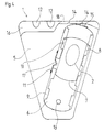
- the armrest 1 has an upper side 4 which is advantageously provided with some form of soft padding or upholstery.
- the under side 5 of the armrest is connected to the pedestal 2. This connection is realised in the preferred embodiment by means of a rail 6 which is disposed between the pedestal 2 and the under side 5 of the armrest 1.
- the under side 5 of the armrest 1 which advantageously manufactured from hard plastic, is interconnected with the rail 6 by the intermediary of a pin 13 in the rear end of the rail.
- the under side 5 is best visible in Figs. 3 and 4.
- the under side 5 of the armrest 1 is interconnected with the rail by a projecting edge 16 which extends out under a front region of the under side of the rail 6.
- the rail 6 is reciprocal in a groove-shaped space which is upwardly defined by the under side 5 and downwardly by the upper side of the projecting edge 16.
- the interconnection 18 which forwardly unites the under side 5 and the edge 16 is suitably of arcuate configuration seen from beneath or above, the centre of arc being the pivot axis or pin 13.
- the rail 6 is in turn connected to the pedestal 2.
- the upper region of the pedestal 2 is designed as a platform 7 with opposing, substantially mutually parallel edges.
- the platform 7 thus has a substantially planar surface whose width is substantially equal to the width of the rail 6.
- the platform 7 of the pedestal 2 has, along its two sides, a projecting edge or flange 8 which, as will disclosed in greater detail below, serves the function of a slip- or sliding guide together with corresponding means on the rail 6.
- the rail 6 is provided with inwardly folded lugs or flaps 9 which are bent in over the rail in such a manner that there is an interspace between the flaps 9 and the rail 6.
- the interspace is substantially the same size as or slightly larger in the vertical direction than the height of the flanges 8. Consequently, the pedestal 2 is movable forwards and rearwards along the rail 6 in such a manner that the platform 7 of the pedestal abuts against the under side of the rail 6 and its flanges 8 are overlapped on their under side by the flaps 9.
- the armrest 1 is, by means of above-mentioned slip- or sliding guide, movable forwards and rearwards in accordance with the double-headed arrow A-B.
- the armrest is provided with a number of distinct arrest positions for its movement forwards and rearwards.
- the arrest positions are such that one user may use the chair in a normal way without displacing the armrests 1, while if a slightly increased force is applied by the user, the armrests 1 may nevertheless be moved out of their current arrest position to another position.
- a number of recesses 10 are provided in at least one of the projecting edges or flanges 8 on the platform 7 of the pedestal 2.
- a spring 11 is disposed at the side of the rail 6 corresponding to that side of the platform 7 of the pedestal 2 where the recesses 10 are provided.
- the spring 11 may be disposed on the outside of the rail 6 and project in over this through a recess in its upwardly folded edge, or be disposed inside the upwardly folded edge and wholly or partly covered by the inwardly folded lugs or flaps 9. Regardless of how the spring 11 is placed, it is provided with a protruding projection 17 which snaps into one of the recesses 10 when these are located in register with the projection 17. If the armrest is, with a force which exceeds the forces which occur on normal use, shifted forwards or rearwards, the projection 17 of the spring 11 is dislodged from its position in any of the recesses 10 and the armrest is then movable to another position which is represented by another recess 10. By such means, a plurality of distinct positions may be provided for the armrest 1 when this is slid forwards or rearwards.
- finger grips 12 are disposed on the under side of the projecting edge 16 in the forward end of the armrest.
- the finger grips 12 which may most closely be described as a number of cup-shaped recesses, preferably four in number for the fingers will make it easier for the user to understand how the hands are ideally placed on movement of the armrest.
- the armrest 1 can, in addition to being moved in its longitudinal direction, also be angled outwards and inwards in relation to the user, at the same time as the armrest 1 is substantially horizontal and its rear end is moved minimally. It is thus the forward end of the armrest 1 which moves in a direction towards or away from the user.
- the rail 6 is pivotal in relation to the armrest 1.
- the rail 6 is connected to the under side 5 of the armrest by the intermediary of the pin 13 and the projecting edge 16 in the forward end of the armrest. A portion of this edge 16 has been cut away in Fig. 4.
- the pivotability or angling function is achieved in that the rail 6 may be pivoted about the pin 13 in relation to the armrest 1. It is also possible to invert this reasoning and assert that the armrest 1 may be pivoted about the pin 13 in relation to the rail 6.
- the armrest can be turned to one or more different positions between the end positions.
- recesses 14 are provided inside the projecting edge 16, provided with the finger grips 12, in the forward end of the armrest 1.
- the end positions each have their recess 14, and each desired intermediate position is represented by one recess 14 each.
- a spring 15 is provided in the forward edge of the rail. The armrest 1 is moved between the different snap engagements, which correspond to the different positions, in that an extra force is applied to the armrest 1.
- the finger grips 12 can also advantageously be used on turning of the armrest 1.
Landscapes
- Health & Medical Sciences (AREA)
- Dentistry (AREA)
- General Health & Medical Sciences (AREA)
- Special Chairs (AREA)
- Chairs Characterized By Structure (AREA)
Applications Claiming Priority (2)
| Application Number | Priority Date | Filing Date | Title |
|---|---|---|---|
| SE0004675 | 2000-12-18 | ||
| SE0004675A SE0004675L (sv) | 2000-12-18 | 2000-12-18 | Justerbart armstöd |
Publications (2)
| Publication Number | Publication Date |
|---|---|
| EP1216632A2 true EP1216632A2 (de) | 2002-06-26 |
| EP1216632A3 EP1216632A3 (de) | 2003-11-05 |
Family
ID=20282269
Family Applications (1)
| Application Number | Title | Priority Date | Filing Date |
|---|---|---|---|
| EP01204671A Withdrawn EP1216632A3 (de) | 2000-12-18 | 2001-12-04 | Verstellbare Armlehne |
Country Status (3)
| Country | Link |
|---|---|
| US (1) | US20020074844A1 (de) |
| EP (1) | EP1216632A3 (de) |
| SE (1) | SE0004675L (de) |
Families Citing this family (5)
| Publication number | Priority date | Publication date | Assignee | Title |
|---|---|---|---|---|
| US20050189807A1 (en) * | 2004-02-27 | 2005-09-01 | Norman Christopher J. | Chair with functional armrest |
| CN101346634B (zh) * | 2005-11-04 | 2012-10-24 | 甲骨文国际公司 | 用于通信网络中的网守的系统和方法 |
| CA2697273A1 (en) * | 2007-08-23 | 2009-02-26 | Herman Miller Inc. | Adjustable armrest and method for the use thereof |
| USD697726S1 (en) | 2012-09-20 | 2014-01-21 | Steelcase Inc. | Chair |
| US11304528B2 (en) | 2012-09-20 | 2022-04-19 | Steelcase Inc. | Chair assembly with upholstery covering |
Citations (1)
| Publication number | Priority date | Publication date | Assignee | Title |
|---|---|---|---|---|
| US5407249A (en) | 1990-10-15 | 1995-04-18 | Bonutti; Peter M. | Armrest assembly |
Family Cites Families (8)
| Publication number | Priority date | Publication date | Assignee | Title |
|---|---|---|---|---|
| US4576351A (en) * | 1984-06-15 | 1986-03-18 | Brink T A | Portable stroke victims arm rest |
| CA2162781C (en) * | 1995-11-14 | 2000-05-23 | David Novis | Arm support device |
| US6076892A (en) * | 1997-06-04 | 2000-06-20 | Knoll, Inc. | Multi-adjustable armrest assembly |
| US5931536A (en) * | 1997-10-16 | 1999-08-03 | Wu; Yao-Chuan | Adjustable armrest of a chair |
| US5927811A (en) * | 1998-02-27 | 1999-07-27 | Shin Yen Enterprise Co., Ltd. | Adjustable chair-armrest assembly |
| DE59906411D1 (de) * | 1998-05-22 | 2003-09-04 | Froli Kunststoffwerk Fromme H | Armstütze, insbesondere für Büro- und Drehstühle |
| AT407003B (de) * | 1999-04-12 | 2000-11-27 | Sdm Hansen Ag | Armauflage für ein sitzmöbel |
| DE29908103U1 (de) * | 1999-05-06 | 1999-07-22 | Hu, Jung-Hua, Tainan Hsien | Bewegungsvorrichtung für eine Armlehne |
-
2000
- 2000-12-18 SE SE0004675A patent/SE0004675L/ not_active Application Discontinuation
-
2001
- 2001-12-04 EP EP01204671A patent/EP1216632A3/de not_active Withdrawn
- 2001-12-17 US US10/015,897 patent/US20020074844A1/en not_active Abandoned
Patent Citations (1)
| Publication number | Priority date | Publication date | Assignee | Title |
|---|---|---|---|---|
| US5407249A (en) | 1990-10-15 | 1995-04-18 | Bonutti; Peter M. | Armrest assembly |
Also Published As
| Publication number | Publication date |
|---|---|
| US20020074844A1 (en) | 2002-06-20 |
| SE0004675D0 (sv) | 2000-12-18 |
| SE0004675L (sv) | 2002-06-19 |
| EP1216632A3 (de) | 2003-11-05 |
Similar Documents
| Publication | Publication Date | Title |
|---|---|---|
| US9955785B2 (en) | Ergonomic productivity workstation having coordinated and harmonized movement of head rest, backrest, seat, leg rest, arm rests, monitor support, and work trays through sitting, standing, and reclining configurations | |
| US7234775B2 (en) | Dynamically balanced seat assembly having independently and arcuately movable seat and backrest and method | |
| US5542746A (en) | Variable posture component system seating device | |
| US6923505B2 (en) | Ergonomically neutral arm support system | |
| JPH01297009A (ja) | 人間工学的椅子の座面 | |
| US9968196B2 (en) | Kinematic mechanisms for furniture | |
| JPH06500944A (ja) | 作業用椅子、特に事務用椅子 | |
| NL8004217A (nl) | Stoel, in het bijzonder stoel voor een datavisie- toestel | |
| EP0723500A1 (de) | Ergonomische mausunterlage | |
| GB2582671A (en) | Seat armrest | |
| EP1658606A2 (de) | Ergonomische maus | |
| EP1216632A2 (de) | Verstellbare Armlehne | |
| US9282826B1 (en) | Ergonomic chair and system | |
| AU2018344896B2 (en) | Posture adaptive work chair | |
| US11490732B2 (en) | Stairlift chair | |
| JP4105916B2 (ja) | 椅子 | |
| JP7770001B2 (ja) | 機能性イス及び機能性座イス | |
| CN112272527A (zh) | 坐式家具 | |
| NL1030423C2 (nl) | Rechtop-armsteun-werkblad. | |
| EP1933666B1 (de) | Ergonomischer arbeitsplatz | |
| JPWO2001064080A1 (ja) | 椅子のロッキング装置 | |
| JP5891012B2 (ja) | 格納椅子 | |
| CN121369870A (zh) | 具伸缩靠背调整机构的可调整椅子 | |
| Adams | Solutions for Reclined Seating in Office Workstation Design | |
| Wyatt | Analysis of the VDT-worker interface |
Legal Events
| Date | Code | Title | Description |
|---|---|---|---|
| PUAI | Public reference made under article 153(3) epc to a published international application that has entered the european phase |
Free format text: ORIGINAL CODE: 0009012 |
|
| AK | Designated contracting states |
Kind code of ref document: A2 Designated state(s): AT BE CH CY DE DK ES FI FR GB GR IE IT LI LU MC NL PT SE TR |
|
| AX | Request for extension of the european patent |
Free format text: AL;LT;LV;MK;RO;SI |
|
| PUAL | Search report despatched |
Free format text: ORIGINAL CODE: 0009013 |
|
| STAA | Information on the status of an ep patent application or granted ep patent |
Free format text: STATUS: THE APPLICATION HAS BEEN WITHDRAWN |
|
| AK | Designated contracting states |
Kind code of ref document: A3 Designated state(s): AT BE CH CY DE DK ES FI FR GB GR IE IT LI LU MC NL PT SE TR |
|
| AX | Request for extension of the european patent |
Extension state: AL LT LV MK RO SI |
|
| 18W | Application withdrawn |
Effective date: 20031021 |