EP1215856A2 - Billing redundant ATM connections - Google Patents
Billing redundant ATM connections Download PDFInfo
- Publication number
- EP1215856A2 EP1215856A2 EP01310316A EP01310316A EP1215856A2 EP 1215856 A2 EP1215856 A2 EP 1215856A2 EP 01310316 A EP01310316 A EP 01310316A EP 01310316 A EP01310316 A EP 01310316A EP 1215856 A2 EP1215856 A2 EP 1215856A2
- Authority
- EP
- European Patent Office
- Prior art keywords
- component
- switch
- counting
- cells
- switchover
- Prior art date
- Legal status (The legal status is an assumption and is not a legal conclusion. Google has not performed a legal analysis and makes no representation as to the accuracy of the status listed.)
- Granted
Links
Images


Classifications
-
- H—ELECTRICITY
- H04—ELECTRIC COMMUNICATION TECHNIQUE
- H04L—TRANSMISSION OF DIGITAL INFORMATION, e.g. TELEGRAPHIC COMMUNICATION
- H04L12/00—Data switching networks
- H04L12/54—Store-and-forward switching systems
- H04L12/56—Packet switching systems
- H04L12/5601—Transfer mode dependent, e.g. ATM
-
- H—ELECTRICITY
- H04—ELECTRIC COMMUNICATION TECHNIQUE
- H04L—TRANSMISSION OF DIGITAL INFORMATION, e.g. TELEGRAPHIC COMMUNICATION
- H04L49/00—Packet switching elements
- H04L49/10—Packet switching elements characterised by the switching fabric construction
- H04L49/104—Asynchronous transfer mode [ATM] switching fabrics
- H04L49/105—ATM switching elements
- H04L49/108—ATM switching elements using shared central buffer
-
- H—ELECTRICITY
- H04—ELECTRIC COMMUNICATION TECHNIQUE
- H04L—TRANSMISSION OF DIGITAL INFORMATION, e.g. TELEGRAPHIC COMMUNICATION
- H04L12/00—Data switching networks
- H04L12/54—Store-and-forward switching systems
- H04L12/56—Packet switching systems
- H04L12/5601—Transfer mode dependent, e.g. ATM
- H04L2012/5625—Operations, administration and maintenance [OAM]
- H04L2012/5627—Fault tolerance and recovery
-
- H—ELECTRICITY
- H04—ELECTRIC COMMUNICATION TECHNIQUE
- H04L—TRANSMISSION OF DIGITAL INFORMATION, e.g. TELEGRAPHIC COMMUNICATION
- H04L12/00—Data switching networks
- H04L12/54—Store-and-forward switching systems
- H04L12/56—Packet switching systems
- H04L12/5601—Transfer mode dependent, e.g. ATM
- H04L2012/5638—Services, e.g. multimedia, GOS, QOS
- H04L2012/5646—Cell characteristics, e.g. loss, delay, jitter, sequence integrity
- H04L2012/5649—Cell delay or jitter
Definitions
- the present invention is related to billing redundant ATM connections. More specifically, the present invention is related to billing redundant ATM connections based on an accurate account based on the total cell counts received, transmitted or dropped obtained from both the primary and the secondary components.
- ATM switches can be used to setup connections between logical interfaces on the switch. These connections can allow data to flow through the switch in small pre defined packets called atm cells.
- the switch hardware can be configured to count the number of cells that have been received, transmitted or dropped through the switch. These cell counts are then utilized by various billing software packages to bill users for the amount of traffic that they have sent through the switch.
- a hardware component (primary component) is backed up by another identical hardware component (secondary component).
- secondary component When the primary component fails, the secondary component takes over. Failure can be defined as physical hardware component failures or as loss of signal/carrier on a fiber carrying data.
- the secondary component taking over from the primary component prevents existing connections that have been setup from being torn down. Minimal data loss is experienced during this transition.
- cell flows through the primary and secondary components will be different depending on the component that is active. Therefore cell counts collected from the primary and secondary components will be different.
- This invention solves the problem of collecting the relevant hardware cell counters, combining them in software and ensuring that the cell counts collected represents an accurate count of total cells received, transmitted or dropped through the ATM switch.
- the present invention pertains to an apparatus for transferring data on a network.
- the apparatus comprises a switch comprising a primary component for switching the data through the switch.
- the apparatus comprises a secondary component for switching the data through the switch if the primary component fails.
- the apparatus comprises a mechanism for counting the data that has been received, transmitted or dropped by the switch without including any redundancy in the counting of the data due to the primary component and secondary component both able to switch data through the switch.
- the present invention pertains to a method for transferring ATM cells on a network.
- the method comprises the steps of switching the ATM cells with an ATM switch of the ATM network having a primary component for switching the cells and a secondary component for switching the cells if the primary component fails. Then there is the step of counting the cells that have been received, transmitted or dropped by the switch without including any redundancy in the counting if the cells due to the primary component and secondary component both able to switch the cells through the switch.
- the apparatus 10 for transferring data on a network 12.
- the apparatus 10 comprises a switch 14 comprising a primary component 16 for switching the data through the switch 14.
- the apparatus 10 comprises a secondary component 18 for switching the data through the switch 14 if the primary component 16 fails.
- the apparatus 10 comprises a mechanism for counting the data that has been received, transmitted or dropped by the switch 14 without including any redundancy in the counting of the data due to the primary component 16 and secondary component 18 both able to switch 14 data through the switch 14.
- the counting mechanism 20 counts data as ATM cells from the network 12 which is an ATM network 12.
- the counting mechanism 20 preferably includes a cell recording module 22 which combines cell counts calculated from the primary and secondary components 16, 18.
- the module collects cell counts for each connection through the switch 14.
- the module preferably counts cell counts from either the primary component 16 or the secondary component 18 depending upon which one is actually having the connection through the switch 14, otherwise known as an active component.
- the primary component 16 and the secondary component 18 each have physical interfaces 24 and a logical interface 26 for both components that maintains a switchover count which counts whenever a physical component takes over the connection because the other component has failed, otherwise called a switchover event, and each physical interface 24 counts the number of cells of the connection that have passed through it.
- the logical interface 26 preferably increases its switchover count whenever it receives a switchover event and clears cell counts on the active component.
- the module counts the cell counts of the logical interface 26 on the active component for each connection in predetermined intervals.
- the module preferably reviews the logical interface 26 at each interval to determine if the component with which it is associated has its switchover count increased since a previous interval.
- the module counts cell counts from each physical interface 24 to determine a total number of cells that has passed through the switch 14, unless the switchover count has increased since the previous interval, in which case the cell count from the previous interval is subtracted from the cell count from the logical interface 26.
- the present invention pertains to a method for transferring ATM cells on a network 12.
- the method comprises the steps of switching the ATM cells with an ATM switch 14 of the ATM network 12 having a primary component 16 for switching the cells and a secondary component 18 for switching the cells if the primary component 16 fails. Then there is the step of counting the cells that have been received, transmitted or dropped by the switch 14 without including any redundancy in the counting if the cells due to the primary component 16 and secondary component 18 both able to switch 14 the cells through the switch 14.
- the counting step includes the step of counting the cells with a cell recording module 22 which combines cell counts from the primary and secondary components 16, 18.
- the counting step preferably includes the step of counting cells with the module for each connection that passes through the switch 14.
- the counting step includes the step of counting with the module from either the primary component 16 or the secondary component 18 depending on which one is actually having the connection through the switch 14, otherwise known as an active component.
- the counting step preferably includes the step of maintaining a switchover count in each logical interface 26 of each component which maintains a switchover count which counts whenever the associated components takes over the connection because the other component has failed, otherwise called a switchover event, and counting with each logical interface 26 the number of cells of the connection that has passed through it.
- the maintaining step includes the step of increasing by each logical interface 26 its switchover count whenever it receives a switchover event and then clearing cell counts on the active component.
- the counting step preferably includes the step of counting the cell counts of each logical interface 26 on the active component for each connection at predetermined intervals.
- the counting step includes the step of reviewing each logical interface 26 at each interval to determine if the component with which it is associated has its switchover count increased since a previous interval.
- the call recording module is responsible for collecting cell counts from various per connection hardware counters. This module implements the software algorithm for combining cell counts collected from the primary and secondary components 16, 18.
- the hardware component that is actively involved in switching cells and carrying data is referred to as the "active" component.
- the active component can be either the primary or secondary component.
- the active component is the primary component 16.
- the primary fails and the secondary takes over the active component is the secondary component 18. If the secondary fails and the primary takes over again, the active component will be the primary component 16.
- the switchover between the primary and secondary components 16, 18 can occur multiple number of times while the switch 14 is active.
- a switchover event is generated on all logical interfaces 26 that are associated with the hardware component that switched over.
- Each logical interface 26 maintains a switchover count.
- the logical interface 26 increases its switchover count and clears the cell counts on the active hardware component.
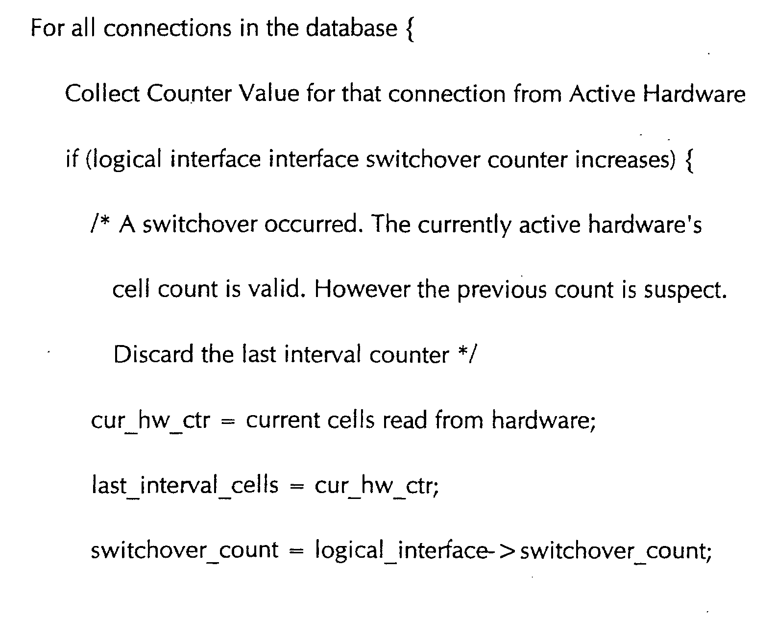
- the following algorithm describes the set of actions taking place when a logical interface 26 receives a switchover event.
- the call recording module keeps track of cell counters on the "active" hardware component by checking them on user-configured intervals. At every user-configured interval, the logical interfaces 26 associated with each connection are looked at to identify if the hardware associated with those interfaces switched over. If the hardware switched over (identified by the increased switchover count) between the previous interval and this one, cells counts are combined in one way. If the hardware did not switch over, cell counts are combined in a different way. The following algorithm describes how the cell counts collected from the currently "active" component are actually combined.
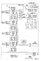
- Figure 1 and Table 1 illustrate how the Counter-combining Algorithm works.
- Figure 1 assumes that cells are uniformly sent at about 100 cells/minute.
- Actual Cell Count Cell Counts obtained from the current hardware component.
- Active H/W Cell Counts from Standby/Active hardware component after Ctrs after Switchover switchover. (The terms “standby” and “active” refer to the standby and active hardware components after switchover.
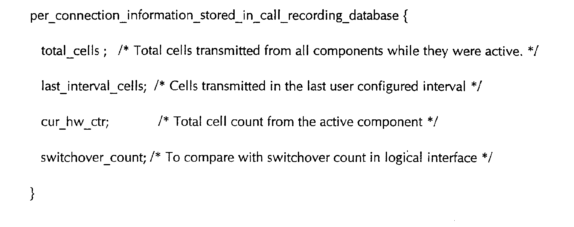
- Delayed Cell Count Cell counts after discarding 1 interval of data Total Cells, Last Interval Cells, Current HW Ctr and Call recording Switchover Ctr are per connection structures stored in the call recording database.
- Logical Interface Switchover Counter is stored in the logical interface switchover counter and is incremented when ever a switchover occurs.
- the Delayed Cell Count is manually calculated by looking at cell counts after switchover occurs. This cell count is obtained by discarding data obtained in an interval where one or more switchovers occur and by adding all other cell count data after a delay of one interval. This count should be similar to the Total Cells count arrived at by using the algorithm.
- Physical Hardware ctr are the cell counts obtained by looking at the actual "active" hardware counters.
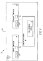
- Figures 2 and 3 show where the cell counts are obtained from.
- Figure 3 shows the physical interface 24 which counts the transmitted cells, and the physical interface 24 which counts the received cells and the dropped cells.
Landscapes
- Engineering & Computer Science (AREA)
- Computer Networks & Wireless Communication (AREA)
- Signal Processing (AREA)
- Data Exchanges In Wide-Area Networks (AREA)
Abstract
Description


| Notation: | |
| Time : | User Configured Interval when the hardware cell counts are collected. In this example the User Configured Interval is set to 60 seconds. |
| Actual Cell Count : | Cell Counts obtained from the current hardware component. |
| Standby |Active H/W : | Cell Counts from Standby/Active hardware component after Ctrs after Switchover switchover. (The terms "standby" and "active" refer to the standby and active hardware components after switchover. |
| Delayed Cell Count : | Cell counts after discarding 1 interval of data |

Logical Interface Switchover Counter is stored in the logical interface switchover counter and is incremented when ever a switchover occurs.
The Delayed Cell Count is manually calculated by looking at cell counts after switchover occurs. This cell count is obtained by discarding data obtained in an interval where one or more switchovers occur and by adding all other cell count data after a delay of one interval. This count should be similar to the Total Cells count arrived at by using the algorithm.
Physical Hardware ctr are the cell counts obtained by looking at the actual "active" hardware counters.
Claims (18)
- An apparatus for transferring data on a network comprising:a switch comprising a primary component for switching the data through the switch;a secondary component for switching the data through the switch if the primary component fails; anda mechanism for counting the data that has been received, transmitted or dropped by the switch without including any redundancy in the counting of the data due to the primary component and secondary component both able to switch data through the switch.
- An apparatus as described in Claim 1 wherein the counting mechanism counts data as ATM cells from the network which is an ATM network.
- An apparatus as described in Claim 2 wherein the counting mechanism includes a cell recording module which combines cell counts calculated from the primary and secondary components.
- An apparatus as described in Claim 3 wherein the module collects cell counts for each connection through the switch.
- An apparatus as described in Claim 4 wherein the module counts cell counts from either the primary component or the secondary component depending upon which one is actually having the connection through the switch, otherwise known as an active component.
- An apparatus as described in Claim 5 wherein the primary component and the secondary component each have physical interfaces and a logical interface for both components that maintains a switchover count which counts whenever a physical component takes over the connection because the other component has failed, otherwise called a switchover event, and each physical interface counts the number of cells of the connection that have passed through it.
- An apparatus as described in Claim 6 wherein the logical interface increases its switchover count whenever it receives a switchover event and clears cell counts on the active component.
- An apparatus as described in Claim 7 wherein the module counts the cell counts of the logical interface on the active component for each connection in predetermined intervals.
- An apparatus as described in Claim 8 wherein the module reviews the logical interface at each interval to determine if the component with which it is associated has its switchover count increased since a previous interval.
- An apparatus as described in Claim 9 wherein the module counts cell counts from each physical interface to determine a total number of cells that has passed through the switch, unless the switchover count has increased since the previous interval, in which case the cell count from the previous interval is subtracted from the cell count from the logical interface.
- A method for transferring ATM cells on a network comprising the steps of:switching the ATM cells with an ATM switch of the ATM network having a primary component for switching the cells and a secondary component for switching the cells if the primary component fails; andcounting the cells that have been received, transmitted or dropped by the switch without including any redundancy in the counting if the cells due to the primary component and secondary component both able to switch the cells through the switch.
- A method as described in Claim 11 wherein the counting step includes the step of counting the cells with a cell recording module which combines cell counts from the primary and secondary components.
- A method as described in Claim 12 wherein the counting step includes the step of counting cells with the module for each connection that passes through the switch.
- A method as described in Claim 13 wherein the counting step includes the step of counting with the module from either the primary component or the secondary component depending on which one is actually having the connection through the switch, otherwise known as an active component.
- A method as described in Claim 14 wherein the counting step includes the step of maintaining a switchover count in each logical interface of each component which maintains a switchover count which counts whenever the associated components takes over the connection because the other component has failed, otherwise called a switchover event, and counting with each logical interface the number of cells of the connection that has passed through it.
- A method as described in Claim 15 wherein the maintaining step includes the step of increasing by each logical interface its switchover count whenever it receives a switchover event and then clearing cell counts on the active component.
- A method as described in Claim 16 wherein the counting step includes the step of counting the cell counts of each logical interface on the active component for each connection at predetermined intervals.
- A method as described in Claim 17 wherein the counting step includes the step of reviewing each logical interface at each interval to determine if the component with which it is associated has its switchover count increased since a previous interval.
Applications Claiming Priority (2)
| Application Number | Priority Date | Filing Date | Title |
|---|---|---|---|
| US740151 | 2000-12-18 | ||
| US09/740,151 US6856626B2 (en) | 2000-12-18 | 2000-12-18 | Billing redundant ATM connections |
Publications (3)
| Publication Number | Publication Date |
|---|---|
| EP1215856A2 true EP1215856A2 (en) | 2002-06-19 |
| EP1215856A3 EP1215856A3 (en) | 2003-05-21 |
| EP1215856B1 EP1215856B1 (en) | 2006-03-22 |
Family
ID=24975258
Family Applications (1)
| Application Number | Title | Priority Date | Filing Date |
|---|---|---|---|
| EP01310316A Expired - Lifetime EP1215856B1 (en) | 2000-12-18 | 2001-12-10 | Billing redundant ATM connections |
Country Status (5)
| Country | Link |
|---|---|
| US (1) | US6856626B2 (en) |
| EP (1) | EP1215856B1 (en) |
| JP (1) | JP2002223232A (en) |
| AT (1) | ATE321401T1 (en) |
| DE (1) | DE60118139T2 (en) |
Families Citing this family (3)
| Publication number | Priority date | Publication date | Assignee | Title |
|---|---|---|---|---|
| US6524912B1 (en) * | 2000-08-31 | 2003-02-25 | Micron Technology, Inc. | Planarization of metal container structures |
| JP4745915B2 (en) * | 2006-08-11 | 2011-08-10 | 富士通株式会社 | Transmission equipment |
| CN116248606A (en) * | 2023-03-10 | 2023-06-09 | 昆山网电科技有限公司 | Redundancy processing method, redundancy switch and redundancy switch system |
Family Cites Families (14)
| Publication number | Priority date | Publication date | Assignee | Title |
|---|---|---|---|---|
| JP3003557B2 (en) * | 1995-10-13 | 2000-01-31 | 日本電信電話株式会社 | Active spare switching device |
| JPH09261229A (en) * | 1996-03-19 | 1997-10-03 | Hitachi Ltd | ATM communication device |
| US6052373A (en) * | 1996-10-07 | 2000-04-18 | Lau; Peter S. Y. | Fault tolerant multicast ATM switch fabric, scalable speed and port expansion configurations |
| ATE389995T1 (en) * | 1997-03-27 | 2008-04-15 | Nokia Siemens Networks Gmbh | REDUNDANT TRANSMISSION SYSTEM WITH SWITCHING OFF A TRANSMISSION ROUTE OF DEFECTIVE TRANSMISSION BEHAVIOR |
| US6011780A (en) * | 1997-05-23 | 2000-01-04 | Stevens Institute Of Technology | Transparant non-disruptable ATM network |
| JPH11122266A (en) * | 1997-10-17 | 1999-04-30 | Fujitsu Ltd | ATM switch and data editing system |
| JPH11127155A (en) * | 1997-10-20 | 1999-05-11 | Fujitsu Ltd | switch |
| US6195351B1 (en) * | 1998-01-28 | 2001-02-27 | 3Com Corporation | Logical switch set |
| JPH11261570A (en) * | 1998-03-10 | 1999-09-24 | Fujitsu Ltd | ATM equipment |
| US6347073B1 (en) * | 1998-04-29 | 2002-02-12 | 3Com Corporation | Method and system for controlling data transfer between a logical switch set and outside nodes |
| JPH11317746A (en) * | 1998-05-06 | 1999-11-16 | Fujitsu Ltd | Quality monitoring method and quality monitoring device for duplicated ATM switch |
| US6512769B1 (en) * | 1998-06-03 | 2003-01-28 | Cisco Technology, Inc. | Method and apparatus for rate-based cell traffic arbitration in a switch |
| US6674756B1 (en) * | 1999-02-23 | 2004-01-06 | Alcatel | Multi-service network switch with multiple virtual routers |
| US6763024B1 (en) * | 1999-10-14 | 2004-07-13 | Alcatel Canada Inc. | Method and devices for cell loss detection in ATM telecommunication devices |
-
2000
- 2000-12-18 US US09/740,151 patent/US6856626B2/en not_active Expired - Lifetime
-
2001
- 2001-12-10 EP EP01310316A patent/EP1215856B1/en not_active Expired - Lifetime
- 2001-12-10 DE DE60118139T patent/DE60118139T2/en not_active Expired - Fee Related
- 2001-12-10 AT AT01310316T patent/ATE321401T1/en not_active IP Right Cessation
- 2001-12-17 JP JP2001382459A patent/JP2002223232A/en active Pending
Also Published As
| Publication number | Publication date |
|---|---|
| EP1215856A3 (en) | 2003-05-21 |
| US6856626B2 (en) | 2005-02-15 |
| DE60118139T2 (en) | 2006-08-24 |
| ATE321401T1 (en) | 2006-04-15 |
| JP2002223232A (en) | 2002-08-09 |
| DE60118139D1 (en) | 2006-05-11 |
| EP1215856B1 (en) | 2006-03-22 |
| US20040213240A1 (en) | 2004-10-28 |
Similar Documents
| Publication | Publication Date | Title |
|---|---|---|
| JP3003051B2 (en) | ATM switch with dual switch plane operation | |
| US6538987B1 (en) | Rapid ring protection switching system | |
| US7058010B2 (en) | Controlled switchover of unicast and multicast data flows in a packet based switching system | |
| US7839772B2 (en) | Line redundant device and method | |
| JPH05252184A (en) | Virtual pass connection device and virtual pass tracing method | |
| US20020089926A1 (en) | Method and apparatus for lossless switchover in a redundant switch fabric | |
| US6016340A (en) | Billing scheme for a telecommunications network | |
| US6580688B1 (en) | Switching transmission units to an equivalent circuit for the purposes of bidirectional asynchronous cell transfer | |
| US5923840A (en) | Method of reporting errors by a hardware element of a distributed computer system | |
| US5084863A (en) | System for interchanging messages in real time between stations interconnected by a loop link, in particular between stations in a telecommunications exchange | |
| US7158721B2 (en) | Performance monitoring of multiple channels in an automatic protection switched network | |
| JP3811007B2 (en) | Virtual connection protection switching | |
| US6246665B1 (en) | Method for attending occurrence of failure in an exchange system that exchanges cells having fixed-length, and interface unit and concentrator equipped in the exchange system using the method | |
| DE60133659T2 (en) | SYNCHRONOUS CHANGE OF THE MEASUREMENT LEVEL | |
| US6856626B2 (en) | Billing redundant ATM connections | |
| WO2007132361A2 (en) | System and method of interface association for interface operational status event monitoring | |
| US7502447B2 (en) | Call failure recording | |
| EP1093263A2 (en) | Method and devices for cell loss detection in ATM telecommunication devices | |
| JPH0382244A (en) | Inter-processor communication system | |
| JP3045144B2 (en) | ATM switch | |
| JP3517164B2 (en) | Communication device with duplex switching function | |
| JP2768762B2 (en) | switch | |
| Yoshikai et al. | Message control channel protocol and performance analysis for distributed ATM Virtual Path self-healing network | |
| KR960015606B1 (en) | Processor State Management Method Using Forward and Reverse Navigation Techniques | |
| JPH10276204A (en) | ATM best effort service providing method using spare bandwidth |
Legal Events
| Date | Code | Title | Description |
|---|---|---|---|
| PUAI | Public reference made under article 153(3) epc to a published international application that has entered the european phase |
Free format text: ORIGINAL CODE: 0009012 |
|
| AK | Designated contracting states |
Kind code of ref document: A2 Designated state(s): AT BE CH CY DE DK ES FI FR GB GR IE IT LI LU MC NL PT SE TR |
|
| AX | Request for extension of the european patent |
Free format text: AL;LT;LV;MK;RO;SI |
|
| PUAL | Search report despatched |
Free format text: ORIGINAL CODE: 0009013 |
|
| AK | Designated contracting states |
Designated state(s): AT BE CH CY DE DK ES FI FR GB GR IE IT LI LU MC NL PT SE TR |
|
| AX | Request for extension of the european patent |
Extension state: AL LT LV MK RO SI |
|
| RAP1 | Party data changed (applicant data changed or rights of an application transferred) |
Owner name: MARCONI INTELLECTUAL PROPERTY (RINGFENCE) INC. |
|
| 17P | Request for examination filed |
Effective date: 20031117 |
|
| 17Q | First examination report despatched |
Effective date: 20031218 |
|
| AKX | Designation fees paid |
Designated state(s): AT BE CH CY DE DK ES FI FR GB GR IE IT LI LU MC NL PT SE TR |
|
| GRAP | Despatch of communication of intention to grant a patent |
Free format text: ORIGINAL CODE: EPIDOSNIGR1 |
|
| GRAS | Grant fee paid |
Free format text: ORIGINAL CODE: EPIDOSNIGR3 |
|
| GRAA | (expected) grant |
Free format text: ORIGINAL CODE: 0009210 |
|
| AK | Designated contracting states |
Kind code of ref document: B1 Designated state(s): AT BE CH CY DE DK ES FI FR GB GR IE IT LI LU MC NL PT SE TR |
|
| PG25 | Lapsed in a contracting state [announced via postgrant information from national office to epo] |
Ref country code: CH Free format text: LAPSE BECAUSE OF FAILURE TO SUBMIT A TRANSLATION OF THE DESCRIPTION OR TO PAY THE FEE WITHIN THE PRESCRIBED TIME-LIMIT Effective date: 20060322 Ref country code: LI Free format text: LAPSE BECAUSE OF FAILURE TO SUBMIT A TRANSLATION OF THE DESCRIPTION OR TO PAY THE FEE WITHIN THE PRESCRIBED TIME-LIMIT Effective date: 20060322 Ref country code: BE Free format text: LAPSE BECAUSE OF FAILURE TO SUBMIT A TRANSLATION OF THE DESCRIPTION OR TO PAY THE FEE WITHIN THE PRESCRIBED TIME-LIMIT Effective date: 20060322 Ref country code: AT Free format text: LAPSE BECAUSE OF FAILURE TO SUBMIT A TRANSLATION OF THE DESCRIPTION OR TO PAY THE FEE WITHIN THE PRESCRIBED TIME-LIMIT Effective date: 20060322 |
|
| REG | Reference to a national code |
Ref country code: GB Ref legal event code: FG4D |
|
| REG | Reference to a national code |
Ref country code: CH Ref legal event code: EP |
|
| REG | Reference to a national code |
Ref country code: IE Ref legal event code: FG4D |
|
| REF | Corresponds to: |
Ref document number: 60118139 Country of ref document: DE Date of ref document: 20060511 Kind code of ref document: P |
|
| PG25 | Lapsed in a contracting state [announced via postgrant information from national office to epo] |
Ref country code: DK Free format text: LAPSE BECAUSE OF FAILURE TO SUBMIT A TRANSLATION OF THE DESCRIPTION OR TO PAY THE FEE WITHIN THE PRESCRIBED TIME-LIMIT Effective date: 20060622 |
|
| PG25 | Lapsed in a contracting state [announced via postgrant information from national office to epo] |
Ref country code: ES Free format text: LAPSE BECAUSE OF FAILURE TO SUBMIT A TRANSLATION OF THE DESCRIPTION OR TO PAY THE FEE WITHIN THE PRESCRIBED TIME-LIMIT Effective date: 20060703 |
|
| REG | Reference to a national code |
Ref country code: SE Ref legal event code: TRGR |
|
| REG | Reference to a national code |
Ref country code: GB Ref legal event code: 732E |
|
| PG25 | Lapsed in a contracting state [announced via postgrant information from national office to epo] |
Ref country code: PT Free format text: LAPSE BECAUSE OF FAILURE TO SUBMIT A TRANSLATION OF THE DESCRIPTION OR TO PAY THE FEE WITHIN THE PRESCRIBED TIME-LIMIT Effective date: 20060822 |
|
| ET | Fr: translation filed | ||
| REG | Reference to a national code |
Ref country code: CH Ref legal event code: PL |
|
| PGFP | Annual fee paid to national office [announced via postgrant information from national office to epo] |
Ref country code: GB Payment date: 20061130 Year of fee payment: 6 |
|
| PG25 | Lapsed in a contracting state [announced via postgrant information from national office to epo] |
Ref country code: IE Free format text: LAPSE BECAUSE OF NON-PAYMENT OF DUE FEES Effective date: 20061211 |
|
| PGFP | Annual fee paid to national office [announced via postgrant information from national office to epo] |
Ref country code: SE Payment date: 20061219 Year of fee payment: 6 |
|
| PGFP | Annual fee paid to national office [announced via postgrant information from national office to epo] |
Ref country code: FR Payment date: 20061220 Year of fee payment: 6 |
|
| PGFP | Annual fee paid to national office [announced via postgrant information from national office to epo] |
Ref country code: DE Payment date: 20061221 Year of fee payment: 6 |
|
| PGFP | Annual fee paid to national office [announced via postgrant information from national office to epo] |
Ref country code: NL Payment date: 20061228 Year of fee payment: 6 |
|
| PG25 | Lapsed in a contracting state [announced via postgrant information from national office to epo] |
Ref country code: MC Free format text: LAPSE BECAUSE OF NON-PAYMENT OF DUE FEES Effective date: 20061231 |
|
| PGFP | Annual fee paid to national office [announced via postgrant information from national office to epo] |
Ref country code: IT Payment date: 20061231 Year of fee payment: 6 |
|
| PLBE | No opposition filed within time limit |
Free format text: ORIGINAL CODE: 0009261 |
|
| STAA | Information on the status of an ep patent application or granted ep patent |
Free format text: STATUS: NO OPPOSITION FILED WITHIN TIME LIMIT |
|
| NLS | Nl: assignments of ep-patents |
Owner name: ERICSSON AB Effective date: 20061123 |
|
| REG | Reference to a national code |
Ref country code: FR Ref legal event code: TP |
|
| 26N | No opposition filed |
Effective date: 20061227 |
|
| PG25 | Lapsed in a contracting state [announced via postgrant information from national office to epo] |
Ref country code: GR Free format text: LAPSE BECAUSE OF FAILURE TO SUBMIT A TRANSLATION OF THE DESCRIPTION OR TO PAY THE FEE WITHIN THE PRESCRIBED TIME-LIMIT Effective date: 20060623 |
|
| PG25 | Lapsed in a contracting state [announced via postgrant information from national office to epo] |
Ref country code: FI Free format text: LAPSE BECAUSE OF FAILURE TO SUBMIT A TRANSLATION OF THE DESCRIPTION OR TO PAY THE FEE WITHIN THE PRESCRIBED TIME-LIMIT Effective date: 20060322 |
|
| PG25 | Lapsed in a contracting state [announced via postgrant information from national office to epo] |
Ref country code: TR Free format text: LAPSE BECAUSE OF FAILURE TO SUBMIT A TRANSLATION OF THE DESCRIPTION OR TO PAY THE FEE WITHIN THE PRESCRIBED TIME-LIMIT Effective date: 20060322 Ref country code: LU Free format text: LAPSE BECAUSE OF NON-PAYMENT OF DUE FEES Effective date: 20061210 |
|
| EUG | Se: european patent has lapsed | ||
| GBPC | Gb: european patent ceased through non-payment of renewal fee |
Effective date: 20071210 |
|
| NLV4 | Nl: lapsed or anulled due to non-payment of the annual fee |
Effective date: 20080701 |
|
| PG25 | Lapsed in a contracting state [announced via postgrant information from national office to epo] |
Ref country code: SE Free format text: LAPSE BECAUSE OF NON-PAYMENT OF DUE FEES Effective date: 20071211 Ref country code: DE Free format text: LAPSE BECAUSE OF NON-PAYMENT OF DUE FEES Effective date: 20080701 |
|
| REG | Reference to a national code |
Ref country code: FR Ref legal event code: ST Effective date: 20081020 |
|
| PG25 | Lapsed in a contracting state [announced via postgrant information from national office to epo] |
Ref country code: CY Free format text: LAPSE BECAUSE OF FAILURE TO SUBMIT A TRANSLATION OF THE DESCRIPTION OR TO PAY THE FEE WITHIN THE PRESCRIBED TIME-LIMIT Effective date: 20060322 Ref country code: NL Free format text: LAPSE BECAUSE OF NON-PAYMENT OF DUE FEES Effective date: 20080701 |
|
| PG25 | Lapsed in a contracting state [announced via postgrant information from national office to epo] |
Ref country code: GB Free format text: LAPSE BECAUSE OF NON-PAYMENT OF DUE FEES Effective date: 20071210 |
|
| PG25 | Lapsed in a contracting state [announced via postgrant information from national office to epo] |
Ref country code: FR Free format text: LAPSE BECAUSE OF NON-PAYMENT OF DUE FEES Effective date: 20071231 |
|
| PG25 | Lapsed in a contracting state [announced via postgrant information from national office to epo] |
Ref country code: IT Free format text: LAPSE BECAUSE OF NON-PAYMENT OF DUE FEES Effective date: 20071210 |