EP1215817A2 - Surface acoustic wave filter - Google Patents
Surface acoustic wave filter Download PDFInfo
- Publication number
- EP1215817A2 EP1215817A2 EP01129825A EP01129825A EP1215817A2 EP 1215817 A2 EP1215817 A2 EP 1215817A2 EP 01129825 A EP01129825 A EP 01129825A EP 01129825 A EP01129825 A EP 01129825A EP 1215817 A2 EP1215817 A2 EP 1215817A2
- Authority
- EP
- European Patent Office
- Prior art keywords
- surface acoustic
- acoustic wave
- inter
- filter
- resonator
- Prior art date
- Legal status (The legal status is an assumption and is not a legal conclusion. Google has not performed a legal analysis and makes no representation as to the accuracy of the status listed.)
- Withdrawn
Links
Images





Classifications
-
- H—ELECTRICITY
- H03—ELECTRONIC CIRCUITRY
- H03H—IMPEDANCE NETWORKS, e.g. RESONANT CIRCUITS; RESONATORS
- H03H9/00—Networks comprising electromechanical or electro-acoustic elements; Electromechanical resonators
- H03H9/46—Filters
- H03H9/64—Filters using surface acoustic waves
- H03H9/6423—Means for obtaining a particular transfer characteristic
- H03H9/6433—Coupled resonator filters
- H03H9/644—Coupled resonator filters having two acoustic tracks
- H03H9/6456—Coupled resonator filters having two acoustic tracks being electrically coupled
- H03H9/6469—Coupled resonator filters having two acoustic tracks being electrically coupled via two connecting electrodes
- H03H9/6473—Coupled resonator filters having two acoustic tracks being electrically coupled via two connecting electrodes the electrodes being electrically interconnected
-
- H—ELECTRICITY
- H03—ELECTRONIC CIRCUITRY
- H03H—IMPEDANCE NETWORKS, e.g. RESONANT CIRCUITS; RESONATORS
- H03H9/00—Networks comprising electromechanical or electro-acoustic elements; Electromechanical resonators
- H03H9/46—Filters
- H03H9/64—Filters using surface acoustic waves
- H03H9/6423—Means for obtaining a particular transfer characteristic
- H03H9/6433—Coupled resonator filters
- H03H9/6436—Coupled resonator filters having one acoustic track only
Definitions
- the present invention relates to a surface acoustic wave filter (SAW filter) for use as a high-frequency device in mobile communication apparatuses.
- SAW filter surface acoustic wave filter
- a surface acoustic wave is a wave propagated as a result of concentration of energy near a surface of an elastic body such as a piezoelectric substrate.
- Electronic devices using the surface acoustic wave such as filters; resonators, delay lines and oscillators, have been put to practical applications.
- FIG. 1 is a schematic view showing an example of the structure of a longitudinally-coupled double-mode resonator filter as one of SAW filters.
- the longitudinally-coupled double-mode resonator filter 1
- three inter-digital transducers 4, 3, 4 (IDTs) for exciting and receiving a surface acoustic wave are arranged in the direction of propagation of the surface acoustic wave on a piezoelectric substrate 10.
- Two reflectors 5 for reflecting the surface acoustic wave are provided on both sides of the three inter-digital transducers 4, 3, 4, in the direction of propagation of the surface acoustic wave.
- each of the inter-digital transducers 3 and 4 two IDT electrodes having a number of (omitted in FIG. 1) electrode fingers 12 are disposed to face each other so that their electrode fingers 12 cross at equal intervals.
- the IDT electrode on one side of the center inter-digital transducer 3 has an input terminal IN of the longitudinally-coupled double-mode resonator filter 1.
- the IDT electrode on the other side of the center inter-digital transducer 3 is connected to the ground.
- the IDT electrode on one side of each of the inter-digital transducers 4 on both sides is connected to the ground.
- the IDT electrodes on the other side of the inter-digital transducers 4 on both sides are connected together and has an output terminal OUT of the longitudinally-coupled double-mode resonator filter 1.
- each reflector 5 a number of (omitted in FIG. 1) electrode fingers similar to the electrode fingers 12 of the inter-digital transducers 3 and 4 are arranged at substantially the same intervals as the intervals in the inter-digital transducers 3 and 4.
- the three inter-digital transducers 4, 3, 4 and the reflectors 5 have substantially an equal aperture length W that is a length in a direction orthogonal to the direction of propagation of the surface acoustic wave.
- the piezoelectric substrate 10 when an alternating voltage is applied to the input terminal IN, the piezoelectric substrate 10 has a distortion between adjacent electrode fingers 12 as a result of the piezoelectric effect, and the surface acoustic wave is excited.
- the surface acoustic wave is most strongly excited when its wavelength and the pitch of the electrode fingers 12 are equal to each other. Since the excited surface acoustic wave is reflected by the two reflectors 5, the vibration energy is enclosed between the two reflectors 5, and a standing wave is generated to resonate. This resonated output can be obtained from the output terminal OUT.
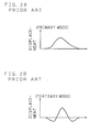
- the standing wave has a dual mode in which a primary-mode wave having a displacement distribution as shown in FIG. 2A and a tertiary-mode wave having a displacement distribution as indicated in FIG. 2B exist.
- the reflection characteristics are shown by representing each of the relationship S11 between the incident wave from the input side (IN) and the wave reflected in the filter to return to the input side and the relationship S22 between the incident wave from the output side (OUT) and the wave reflected in the filter to return to the output side by a voltage standing wave ratio (VSWR).
- the voltage standing wave ratio (VSWR) is the ratio of the maximum voltage and the minimum voltage when the magnitude of the standing wave generated on the propagation path is shown in voltage. As the value becomes closer to 1, the matching state is improved.
- the characteristic S11 shows a value substantially 2 or less within the pass band and is thus satisfactory, but the characteristic S22 is inferior to the characteristic S11.
- the longitudinally-coupled double-mode resonator filters 1 as described above are vertically connected in two stages on a piezoelectric substrate 11. As a result, the vicinity of the cutoff frequency on the high-frequency side was suppressed. However, this structure was suffered from a large insertion loss (difference between the attenuation when the filter was inserted and the attenuation when the filter was not inserted).
- Japanese Laid-Open Patent Publication No. 8-191229 discloses a "longitudinally-coupled double-mode resonator SAW filter".
- the inter-center intervals of the facing innermost electrode fingers of a center IDT and of each of side IDTs are different on the right and left sides.
- the present invention has been made with the aim of solving the above problems, and an object of the present invention is to provide a surface acoustic wave filter having high sharpness in the vicinity of the cutoff frequency on the high-frequency side of the pass band and capable of obtaining sufficient attenuation and a good input and output matching state.
- a surface acoustic wave filter comprises a longitudinally-coupled double-mode resonator filter in which a plurality of inter-digital transducers for exciting and receiving a surface acoustic wave are arranged adjacent to each other in the direction of propagation of the surface acoustic wave, and a resonator having one or a plurality of inter-digital transducers for exciting and receiving a surface acoustic wave.
- the longitudinally-coupled double-mode resonator filter and the resonator are connected in series.
- the cutoff frequency on the high-frequency side of the pass band of the longitudinally-coupled double-mode resonator filter and the antiresonant frequency of the resonator are substantially equal.
- Two reflectors for reflecting the surface acoustic wave are provided on both sides of the plurality of inter-digital transducers arranged in the longitudinally-coupled double-mode resonator filter, in the propagation direction. Vibration energy of the surface acoustic wave can be enclosed between the two reflectors.
- the resonator is a one-port resonator.
- Two reflectors for reflecting the surface acoustic wave are provided on both sides of the resonator, in the direction of propagation of the surface acoustic wave.
- the longitudinally-coupled double-mode resonator filter and the resonator are mounted on a single piezoelectric substrate. It is therefore possible to realize a surface acoustic wave filter having smaller dimensions.
- FIG. 5 is a schematic view showing an example of the structure of a one-port resonator as a resonator using a surface acoustic wave.
- this one-port resonator two reflectors 7 for reflecting a surface acoustic wave are mounted on a piezoelectric substrate 9 on both sides of an inter-digital transducer 6 (IDT) for exciting and receiving the surface acoustic wave, in the direction of propagation of the surface acoustic wave.
- IDT inter-digital transducer 6
- inter-digital transducer 6 two IDT electrodes having a number of (omitted in FIG. 5) electrode fingers 13 are disposed to face each other so that their electrode fingers 13 cross at equal intervals.
- the IDT electrode on one side of the inter-digital transducer 6 has an input terminal IN of the one-port resonator 2, while the IDT electrode on the other side has an output terminal OUT.
- each reflector 7 a number of (omitted in FIG. 5) electrode fingers similar to the electrode fingers 13 of the inter-digital transducer 6 are arranged at substantially the same intervals as the intervals in the inter-digital transducer 6.
- the piezoelectric substrate 9 when an alternating voltage is applied across the input terminal IN and output terminal OUT, the piezoelectric substrate 9 has a distortion between adjacent electrode fingers 13 as a result of the piezoelectric effect, and the surface acoustic wave is excited.
- the surface acoustic wave is most strongly excited when its wavelength and the pitch of the electrode fingers 13 are equal to each other. Since the excited surface acoustic wave is reflected by the two reflectors 7, the vibration energy is enclosed between the two reflectors 7, and a standing wave is generated to resonate.
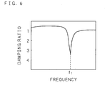
- the one-port resonator 2 has the frequency characteristics as shown in FIG. 6, for example, and has an antiresonant frequency f1.
- the longitudinally-coupled double-mode resonator filter 1 and the one-port resonator 2 are connected in series, and the cutoff frequency on the high-frequency side of the pass band of the longitudinally-coupled double-mode resonator filter 1 and the antiresonant frequency f1 of the one-port resonator 2 are substantially equal.
- the pass band characteristics show higher sharpness in the vicinity of the cutoff frequency on the high-frequency side, and sufficient attenuation is obtained.
- a pitch of electrode fingers in the inter-digital transducers of the resonator is larger than a pitch of electrode fingers in the inter-digital transducers of the longitudinally-coupled double-mode resonator filter. Since antiresonant frequency of the inter-digital transducers of the resonator is adjusted by adjusting the wavelength thereof, the antiresonant frequency of the inter-digital transducers of the resonator is adjusted to a frequency on the high-frequency side of the cutoff frequency of the longitudinally-coupled double-mode resonator filter in the present invention.
- the longitudinally-coupled double-mode resonator filter is provided with three inter-digital transducers, since more than two inter-digital transducers are indispensable in order to obtain pass band higher than 75 MHz (with the fractional bandwidth of 4.1 to 4.3 %). Since the longitudinally-coupled double-mode resonator filter includes only three inter-digital transducers, which meet the minimal requirements, the number of the design parameters to set for the filter can be reduced.
- FIG. 7 is a schematic view showing the structures of essential sections of the embodiment of a surface acoustic wave filter (SAW filter) according to the present invention.
- SAW filter is constructed by connecting a longitudinally-coupled double-mode resonator filter 1 and a one-port resonator 2 in series on a piezoelectric substrate 8.
- inter-digital transducers 4, 3, 4 for exciting and receiving a surface acoustic wave are arranged in the direction of propagation of the surface acoustic wave.
- Two reflectors 5 for reflecting the surface acoustic wave are provided on both sides of the three inter-digital transducers 4, 3, 4, in the direction of propagation of the surface acoustic wave.
- each of the inter-digital transducers 3 and 4 two IDT electrodes having a number of (omitted in FIG. 7) electrode fingers 12 are disposed to face each other so that their electrode fingers 12 cross at equal intervals.
- the filter characteristics are adjusted.
- each reflector 5 a number of (omitted in FIG. 7) electrode fingers similar to the electrode fingers 12 of the inter-digital transducers 3 and 4 are arranged at substantially the same intervals as the intervals in the inter-digital transducers 3 and 4.
- the three inter-digital transducers 4, 3, 4 and the reflectors 5 have substantially an equal aperture length W1 that is a length in a direction orthogonal to the direction of propagation of the surface acoustic wave. However, their aperture lengths W1 are not necessarily equal.
- two reflectors 7 for reflecting a surface acoustic wave are provided on both sides of the inter-digital transducer 6 for exciting and reflecting the surface acoustic wave, in the direction of propagation of the surface acoustic wave.
- two IDT electrodes having a number of (omitted in FIG. 7) electrode fingers 13 are disposed to face each other so that their electrode fingers 13 cross at equal intervals.
- each reflector 7 a number of (omitted in FIG. 7) electrode fingers similar to the electrode fingers 13 of the inter-digital transducer 6 are arranged at substantially the same intervals as the intervals in the inter-digital transducer 6.
- the inter-digital transducer 6 and the reflectors 7 have substantially an equal aperture length W2 that is a length in a direction orthogonal to the direction of propagation of the surface acoustic wave. However, their aperture lengths W2 are not necessarily equal.
- the IDT electrode on one side of the center inter-digital transducer 3 has an input terminal IN of this SAW filter.
- the IDT electrode on the other side of the center inter-digital transducer 3 is connected to the ground.
- the IDT electrode on one side of each of the inter-digital transducers 4 on both sides is connected to the ground, while the IDT electrodes on the other side of the inter-digital transducers 4 on both sides are connected together and then connected to a terminal of the one-port resonator 2.
- the IDT electrodes on the other side of the inter-digital transducers 4 of the longitudinally-coupled double-mode resonator filter 1 have a common connection with the IDT electrode on one side of the inter-digital transducer 6 of the one-port resonator 2.
- the IDT electrode on the other side of the inter-digital transducer 6 has the output terminal OUT of this SAW filter.
- the piezoelectric substrate 8 when an alternating voltage is applied to the input terminal IN, the piezoelectric substrate 8 has a distortion between adjacent electrode fingers 12 as a result of the piezoelectric effect of the longitudinally-coupled double-mode resonator filter 1, and the surface acoustic wave is excited.
- the surface acoustic wave is most strongly excited when its wavelength and the pitch of the electrode fingers 12 are equal to each other. Since the excited surface acoustic wave is reflected by the two reflectors 5, the vibration energy is enclosed between the two reflectors 5, and a standing wave is generated to resonate. This resonated output is supplied to the one-port resonator 2.
- the piezoelectric substrate 8 upon the supply of the output of the longitudinally-coupled double-mode resonator filter 1, the piezoelectric substrate 8 has a distortion between adjacent electrode fingers 13 as a result of the piezoelectric effect, and the surface acoustic wave is excited.
- the surface acoustic wave is most strongly excited when its wavelength and the pitch of the electrode fingers 13 are equal to each other. Since the excited surface acoustic wave is reflected by the two reflectors 7, the vibration energy is enclosed between the two reflectors 7, and a standing wave is generated to resonate. This resonated output is outputted from the output terminal OUT of the SAW filter.
- the one-port resonator 2 has the frequency characteristics as shown in FIG. 6, and has an antiresonant frequency f1.
- This antiresonant frequency f1 and the cutoff frequency on the high-frequency side of the pass band of the longitudinally-coupled double-mode resonator filter 1 are substantially equal.
- the overall pass band characteristic of the SAW filter achieves high sharpness in the vicinity of the cutoff frequency on the high-frequency side, thereby obtaining sufficient attenuation.
- the piezoelectric substrate 8 it is possible to use 42° Y (cut) - X (propagation) LiTaO 3 , 36° Y-X LiTaO 3 , 64° Y-X LiNbO 3 , 41° Y-X LiNbO 3 or 128° Y-X LiNbO 3 , and it is also possible to use X-cut LiTaO 3 or X-cut LiNbO 3 .
- other piezoelectric body such as quartz and langasite may also be used for the piezoelectric substrate 8.
- the material for the inter-digital transducer (IDT) and the reflector is Al or Al-Cu (1%).
- the coating thickness of the inter-digital transducer is, in order to obtain 1.7 to 2.0 GHz as the pass band for example, 80 to 220 nm, preferably 140 to 180 nm in view of the band-pass characteristics (the band-pass width and the sharpness in the vicinity of the cutoff frequency).
- the connected length is an effective length.
- the reflectors 5 are included in the structure of the longitudinally-coupled double-mode resonator filter 1 in the above explanation, the reflectors 5 are not essential. A structure having no reflectors 5 can be realized depending on the number of the inter-digital transducers 3 and 4 and the positioning method, the use of reflection on the crystal end face, and the like. Furthermore, in the one-port resonator 2, it is possible to use an inter-digital transducer 6 having no reflectors 7.
- the inter-digital transducers are sometimes positioned to cross each other at right angles.
- the resonator is not necessarily limited to one port.
- a structure using a two-port resonator may be used.
- the process of designing the above-described SAW filter is as follows. First, the parameters of one stage of the longitudinally-coupled double-mode resonator filter 1 are designed so as to achieve a high suppression on the low-frequency side of the pass band and have high sharpness on the low-frequency side.
- the suppression and sharpness on the high-frequency side of the pass band are designed so that the antiresonant frequency of the one-port resonator 2 and the cutoff frequency on the high-frequency side of the pass band are substantially equal.
- the wavelength tilt the pitch of the electrode fingers
- the aperture length and the number of the electrode fingers are adjusted. More specifically, in the one-port resonator 2, the aperture length that affects the filter waveform and the number of electrode fingers 13 and the number of electrode fingers of the reflectors 7 are adjusted so as to adjust the filter waveform of the pass band.
- the parameters of the one-port resonator are adjusted so that the above-mentioned characteristics S11 and S22 are similar in the vicinity of the pass band.
- the parameters of the longitudinally-coupled double-mode resonator filter 1 are further adjusted so as to adjust the pass band width and the voltage standing wave ratio (VSWR) in the pass band.
- the number of the electrode fingers of the inter-digital transducer 3 was 27, the number of the electrode fingers of the inter-digital transducer 4 was 19, the wavelength (twice the pitch of the electrode fingers) of the inter-digital transducers 3 and 4 was 2.13 ⁇ m, the metallization ratio of the electrode fingers of the inter-digital transducers 3 and 4 was 65, the wavelength (twice the pitch of the electrode fingers) of the reflector 5 was 2.19 ⁇ m, the metallization ratio of the reflector 5 was 65, and the aperture length was 170 ⁇ m.
- the number of the electrode fingers of the inter-digital transducer 6 was 251
- the wavelength (twice the pitch of the electrode fingers) of the inter-digital transducer 6 was 2.14 ⁇ m
- the metallization ratio of the inter-digital transducer 6 was 50
- the wavelength (twice the pitch of the electrode fingers) of the reflector 7 was 2.14 ⁇ m
- the metallization ratio of the reflector 7 was 50
- the aperture length was 50 ⁇ m.
- FIG. 8A shows the pass band characteristics of the surface acoustic wave filter according to Experiment 1.
- the reflection characteristics are shown by representing each of the relationship S11 between the incident wave from the input side (IN) and the wave reflected in the filter to return to the input side and the relationship S22 between the incident wave from the output side (OUT) and the wave reflected in the filter to return to the output side by a voltage standing wave ratio (VSWR).
- VSWR voltage standing wave ratio
- the pass band was 1805 to 1880 MHz.
- the wavelength is mainly adjusted, but other parameters are substantially the same.
- FIG. 9A shows the pass band characteristics when the antiresonant frequency of the one-port resonator 2 was shifted to a higher frequency side in the structure (FIG. 7) similar to that of the above-described SAW filter. Since the VSWR characteristics of the characteristics S11 and S22 did not match as shown in FIG. 9B, both the sharpness (FIG. 9A) and the VSWR characteristics (FIG. 9B) were inferior to those of FIGS. 8A and 8B.
- the number of the electrode fingers of the inter-digital transducer 3 was 37
- the number of the electrode fingers of the inter-digital transducer 4 was 25
- the wavelength (twice the pitch of the electrode fingers) of the inter-digital transducers 3 and 4 was 2.035 ⁇ m
- the metallization ratio of the electrode fingers of the inter-digital transducers 3 and 4 was 60
- the wavelength (twice the pitch of the electrode fingers) of the reflector 5 was 2.081 ⁇ m
- the metallization ratio of the reflector 5 was 60
- the aperture length was 90 ⁇ m.
- the number of the electrode fingers of the inter-digital transducer 6 was 251
- the wavelength (twice the pitch of the electrode fingers) of the inter-digital transducer 6 was 2.050 ⁇ m
- the metallization ratio of the inter-digital transducer 6 was 50
- the wavelength (twice the pitch of the electrode fingers) of the reflector 7 was 2.050 ⁇ m
- the metallization ratio of the reflector 7 was 50
- the aperture length was 50 ⁇ m.
- FIG. 10A shows the pass band characteristics of the surface acoustic wave filter according to Experiment 2.
- the reflection characteristics are shown by representing each of the relationship S11 between the incident wave from the input side (IN) and the wave reflected in the filter to return to the input side and the relationship S22 between the incident wave from the output side (OUT) and the wave reflected in the filter to return to the output side by a voltage standing wave ratio (VSWR).
- VSWR voltage standing wave ratio
- the SAW filter according to the present invention is applicable in a frequency band between 1.8 and 1.9 GHz.
- Experiment 1 shows the present invention in respect of the frequency band of 1700 to 1800 MHz
- Experiment 2 illustrates the present invention in respect of the frequency band of 1.9 to 2.0 GHz.
- the present invention is also applicable in the RF and IF frequency bands of mobile communications, particularly, the 300 to 500 MHz band, 800 to 900 MHz band, 1500 MHz band, 1.9 to 2.1 GHz band and 2.4 to 2.5 GHz band.
Landscapes
- Physics & Mathematics (AREA)
- Acoustics & Sound (AREA)
- Surface Acoustic Wave Elements And Circuit Networks Thereof (AREA)
Abstract
Description
Claims (7)
- A surface acoustic wave filter comprising a longitudinally-coupled double-mode resonator filter (1) in which a plurality of inter-digital transducers (3, 4) for exciting and receiving a surface acoustic wave are arranged adjacent to each other in a direction of propagation of the surface acoustic wave,
characterized by further comprising a resonator (2) having one or a plurality of inter-digital transducers (6) for exciting and receiving a surface acoustic wave, the resonator (2) being connected to said longitudinally-coupled double-mode resonator filter (1) in series,
wherein a cutoff frequency on a high-frequency side of a pass band of said longitudinally-coupled double-mode resonator filter (1) and an antiresonant frequency of said resonator (2) are substantially equal. - A surface acoustic wave filter comprising a longitudinally-coupled double-mode resonator filter (1) in which a plurality of inter-digital transducers (3, 4) for exciting and receiving a surface acoustic wave are arranged adjacent to each other in a direction of propagation of the surface acoustic wave,
characterized by further comprising a resonator (2) having one or a plurality of inter-digital transducers (6) for exciting and receiving a surface acoustic wave, the resonator (2) being connected to said longitudinally-coupled double-mode resonator filter (1) in series,
wherein a pitch of electrode fingers (13) in the inter-digital transducers (6) of the resonator (2) is larger than a pitch of electrode fingers (12) in the inter-digital transducers (3, 4) of the longitudinally-coupled double-mode resonator filter (1). - The surface acoustic wave filter according to Claim 1 or 2, characterized in that two reflectors (5) for reflecting the surface acoustic wave are provided on both sides of the plurality of inter-digital transducers (3, 4) arranged in said longitudinally-coupled double-mode resonator filter (1), in the propagation direction, so as to enclose vibration energy of the surface acoustic wave between said two reflectors (5).
- The surface acoustic wave filter according to one of Claims 1 through 3, characterized in that said resonator (2) is a one-port resonator.
- The surface acoustic wave filter according to one of Claims 1 through 4, characterized in that two reflectors (7) for reflecting the surface acoustic wave are provided on both sides of said resonator (2), in the direction of propagation of the surface acoustic wave.
- The surface acoustic wave filter according to one of Claims 1 through 5, characterized in that said longitudinally-coupled double-mode resonator filter (1) and said resonator (2) are mounted on a single piezoelectric substrate.
- The surface acoustic wave filter according to one of Claims 1 through 6, characterized in that said longitudinally-coupled double-mode resonator filter (1) is provided with three inter-digital transducers (3, 4).
Applications Claiming Priority (2)
| Application Number | Priority Date | Filing Date | Title |
|---|---|---|---|
| JP2000382849A JP2002185284A (en) | 2000-12-15 | 2000-12-15 | Surface acoustic wave filter |
| JP2000382849 | 2000-12-15 |
Publications (2)
| Publication Number | Publication Date |
|---|---|
| EP1215817A2 true EP1215817A2 (en) | 2002-06-19 |
| EP1215817A3 EP1215817A3 (en) | 2006-05-03 |
Family
ID=18850598
Family Applications (1)
| Application Number | Title | Priority Date | Filing Date |
|---|---|---|---|
| EP01129825A Withdrawn EP1215817A3 (en) | 2000-12-15 | 2001-12-14 | Surface acoustic wave filter |
Country Status (4)
| Country | Link |
|---|---|
| US (1) | US6781483B2 (en) |
| EP (1) | EP1215817A3 (en) |
| JP (1) | JP2002185284A (en) |
| CN (1) | CN1360395A (en) |
Cited By (1)
| Publication number | Priority date | Publication date | Assignee | Title |
|---|---|---|---|---|
| US20210384925A1 (en) * | 2019-03-13 | 2021-12-09 | Murata Manufacturing Co., Ltd. | Multiplexer, radio-frequency module, and communication apparatus |
Families Citing this family (6)
| Publication number | Priority date | Publication date | Assignee | Title |
|---|---|---|---|---|
| WO2003063561A1 (en) * | 2002-01-24 | 2003-07-31 | Mitsubishi Materials Corporation | Printed-circuit board, electronic part having shield structure, and radio communication apparatus |
| JP3764731B2 (en) | 2002-10-18 | 2006-04-12 | 富士通メディアデバイス株式会社 | Multimode surface acoustic wave filter and duplexer |
| JP2006268578A (en) * | 2005-03-24 | 2006-10-05 | Fuji Xerox Co Ltd | Information providing system and image formation device |
| JP4867997B2 (en) * | 2006-12-25 | 2012-02-01 | 株式会社村田製作所 | Elastic wave device |
| SE541055C2 (en) * | 2017-05-30 | 2019-03-19 | Aldo Jesorka | A surface acoustic wave resonant sensor |
| CN119628595B (en) * | 2025-02-11 | 2025-09-23 | 深圳新声半导体有限公司 | Surface acoustic wave resonator and filter |
Family Cites Families (18)
| Publication number | Priority date | Publication date | Assignee | Title |
|---|---|---|---|---|
| DE69323163T2 (en) * | 1992-12-01 | 1999-06-02 | Japan Radio Co. Ltd., Mitaka, Tokio/Tokyo | Acoustic surface wave filter and mobile communication system with such a filter |
| JP2888739B2 (en) | 1993-09-14 | 1999-05-10 | 日本無線株式会社 | Surface acoustic wave filter |
| JP3191473B2 (en) | 1993-03-09 | 2001-07-23 | 三菱電機株式会社 | Surface acoustic wave filter |
| JP3139225B2 (en) | 1993-07-08 | 2001-02-26 | 株式会社村田製作所 | Surface acoustic wave filter |
| JP3424971B2 (en) | 1994-01-20 | 2003-07-07 | 松下電器産業株式会社 | Surface acoustic wave filter |
| JP3218855B2 (en) | 1994-05-11 | 2001-10-15 | 株式会社村田製作所 | Surface acoustic wave device |
| JP3393945B2 (en) | 1995-01-10 | 2003-04-07 | 東洋通信機株式会社 | Vertically coupled dual mode SAW filter |
| JPH08265087A (en) * | 1995-03-22 | 1996-10-11 | Mitsubishi Electric Corp | Surface acoustic wave filter |
| JPH098599A (en) | 1995-06-16 | 1997-01-10 | Toyo Commun Equip Co Ltd | Vertically coupled dual mode SAW filter |
| EP0757438B1 (en) * | 1995-07-25 | 2001-08-16 | Murata Manufacturing Co., Ltd. | Surface acoustic wave device |
| JP3309721B2 (en) | 1995-07-25 | 2002-07-29 | 株式会社村田製作所 | Surface acoustic wave device |
| JPH09162695A (en) | 1995-12-14 | 1997-06-20 | Murata Mfg Co Ltd | Surface acoustic wave device |
| EP0782255B1 (en) * | 1995-12-28 | 2002-03-27 | Murata Manufacturing Co., Ltd. | Longitudinal coupling type surface acoustic wave resonator filter |
| JP3514015B2 (en) | 1995-12-28 | 2004-03-31 | 株式会社村田製作所 | Surface acoustic wave device and method of manufacturing the same |
| JP3175581B2 (en) | 1996-03-14 | 2001-06-11 | 株式会社村田製作所 | Surface acoustic wave device |
| JPH1065481A (en) | 1996-08-13 | 1998-03-06 | Toyo Commun Equip Co Ltd | Surface acoustic wave filter |
| EP0998039B1 (en) * | 1997-07-18 | 2016-12-28 | Murata Manufacturing Co., Ltd. | Surface acoustic wave filter |
| JP3371849B2 (en) * | 1999-04-28 | 2003-01-27 | 株式会社村田製作所 | SAW resonator, composite SAW filter and SAW filter |
-
2000
- 2000-12-15 JP JP2000382849A patent/JP2002185284A/en active Pending
-
2001
- 2001-12-13 US US10/022,096 patent/US6781483B2/en not_active Expired - Lifetime
- 2001-12-14 EP EP01129825A patent/EP1215817A3/en not_active Withdrawn
- 2001-12-14 CN CN01144302.2A patent/CN1360395A/en active Pending
Cited By (2)
| Publication number | Priority date | Publication date | Assignee | Title |
|---|---|---|---|---|
| US20210384925A1 (en) * | 2019-03-13 | 2021-12-09 | Murata Manufacturing Co., Ltd. | Multiplexer, radio-frequency module, and communication apparatus |
| US12132504B2 (en) * | 2019-03-13 | 2024-10-29 | Murata Manufacturing Co., Ltd. | Multiplexer, radio-frequency module, and communication apparatus |
Also Published As
| Publication number | Publication date |
|---|---|
| JP2002185284A (en) | 2002-06-28 |
| EP1215817A3 (en) | 2006-05-03 |
| US6781483B2 (en) | 2004-08-24 |
| US20020075102A1 (en) | 2002-06-20 |
| CN1360395A (en) | 2002-07-24 |
Similar Documents
| Publication | Publication Date | Title |
|---|---|---|
| US6570470B2 (en) | Surface acoustic wave ladder filter utilizing parallel resonators with different resonant frequencies | |
| US6346864B1 (en) | Saw resonator filter and duplexer utilizing SH waves, substrate edge reflection, and sub-interdigital transducer portions | |
| EP1337039B1 (en) | Surface acoustic wave device and communications apparatus | |
| US6353371B1 (en) | Transversely coupled resonator type surface acoustic wave filter and longitudinally coupled resonator type surface acoustic wave filter | |
| JPH08265087A (en) | Surface acoustic wave filter | |
| JP2002314366A (en) | Surface acoustic wave filter, surface acoustic wave device, and communication device | |
| EP1037385B1 (en) | Surface acoustic wave filter, duplexer, and communications device | |
| JPH05267990A (en) | Vertically coupled double-mode SAW filter | |
| JPH0856135A (en) | Surface acoustic wave device | |
| US6297713B1 (en) | Surface acoustic wave device with split electrodes and outermost electrodes of a different width than the split electrodes | |
| US6933803B2 (en) | Surface acoustic wave filter, branching filter, and communication apparatus | |
| US6828879B2 (en) | Longitudinal coupled multiple mode surface acoustic wave filter | |
| US6781483B2 (en) | Surface acoustic wave filter | |
| US6429569B1 (en) | Surface acoustic wave device and communication apparatus | |
| JP3181090B2 (en) | Vertically coupled dual mode leaky SAW filter | |
| US6531937B2 (en) | Edge reflection type surface acoustic wave filter | |
| JP2002217680A (en) | Ladder type surface acoustic wave filter | |
| JP3137394B2 (en) | Vertically coupled dual mode leaky SAW filter | |
| JP3290164B2 (en) | Surface acoustic wave filter | |
| JP3261353B2 (en) | Method for improving characteristics of surface acoustic wave device | |
| JP2002290196A (en) | Longitudinally coupled dual-mode surface acoustic wave filter | |
| JP2000013174A (en) | Resonator type SAW filter | |
| JPH09331230A (en) | Surface acoustic wave device |
Legal Events
| Date | Code | Title | Description |
|---|---|---|---|
| PUAI | Public reference made under article 153(3) epc to a published international application that has entered the european phase |
Free format text: ORIGINAL CODE: 0009012 |
|
| AK | Designated contracting states |
Kind code of ref document: A2 Designated state(s): AT BE CH CY DE DK ES FI FR GB GR IE IT LI LU MC NL PT SE TR |
|
| AX | Request for extension of the european patent |
Free format text: AL;LT;LV;MK;RO;SI |
|
| PUAL | Search report despatched |
Free format text: ORIGINAL CODE: 0009013 |
|
| AK | Designated contracting states |
Kind code of ref document: A3 Designated state(s): AT BE CH CY DE DK ES FI FR GB GR IE IT LI LU MC NL PT SE TR |
|
| AX | Request for extension of the european patent |
Extension state: AL LT LV MK RO SI |
|
| 17P | Request for examination filed |
Effective date: 20060511 |
|
| 17Q | First examination report despatched |
Effective date: 20060705 |
|
| AKX | Designation fees paid |
Designated state(s): DE FI FR GB |
|
| 17Q | First examination report despatched |
Effective date: 20060705 |
|
| STAA | Information on the status of an ep patent application or granted ep patent |
Free format text: STATUS: THE APPLICATION HAS BEEN WITHDRAWN |
|
| 18W | Application withdrawn |
Effective date: 20080718 |