EP1215619B1 - Verfahren zur Überwachung des Innenraums eines Kraftfahrzeuges - Google Patents
Verfahren zur Überwachung des Innenraums eines Kraftfahrzeuges Download PDFInfo
- Publication number
- EP1215619B1 EP1215619B1 EP01127922A EP01127922A EP1215619B1 EP 1215619 B1 EP1215619 B1 EP 1215619B1 EP 01127922 A EP01127922 A EP 01127922A EP 01127922 A EP01127922 A EP 01127922A EP 1215619 B1 EP1215619 B1 EP 1215619B1
- Authority
- EP
- European Patent Office
- Prior art keywords
- infrared
- interior
- image
- camera
- images
- Prior art date
- Legal status (The legal status is an assumption and is not a legal conclusion. Google has not performed a legal analysis and makes no representation as to the accuracy of the status listed.)
- Expired - Lifetime
Links
Images

Classifications
-
- G—PHYSICS
- G08—SIGNALLING
- G08B—SIGNALLING SYSTEMS, e.g. PERSONAL CALLING SYSTEMS; ORDER TELEGRAPHS; ALARM SYSTEMS
- G08B13/00—Burglar, theft or intruder alarms
- G08B13/18—Actuation by interference with heat, light, or radiation of shorter wavelength; Actuation by intruding sources of heat, light, or radiation of shorter wavelength
- G08B13/189—Actuation by interference with heat, light, or radiation of shorter wavelength; Actuation by intruding sources of heat, light, or radiation of shorter wavelength using passive radiation detection systems
- G08B13/194—Actuation by interference with heat, light, or radiation of shorter wavelength; Actuation by intruding sources of heat, light, or radiation of shorter wavelength using passive radiation detection systems using image scanning and comparing systems
- G08B13/196—Actuation by interference with heat, light, or radiation of shorter wavelength; Actuation by intruding sources of heat, light, or radiation of shorter wavelength using passive radiation detection systems using image scanning and comparing systems using television cameras
- G08B13/19639—Details of the system layout
- G08B13/19647—Systems specially adapted for intrusion detection in or around a vehicle
-
- G—PHYSICS
- G01—MEASURING; TESTING
- G01S—RADIO DIRECTION-FINDING; RADIO NAVIGATION; DETERMINING DISTANCE OR VELOCITY BY USE OF RADIO WAVES; LOCATING OR PRESENCE-DETECTING BY USE OF THE REFLECTION OR RERADIATION OF RADIO WAVES; ANALOGOUS ARRANGEMENTS USING OTHER WAVES
- G01S17/00—Systems using the reflection or reradiation of electromagnetic waves other than radio waves, e.g. lidar systems
- G01S17/02—Systems using the reflection of electromagnetic waves other than radio waves
- G01S17/04—Systems determining the presence of a target
-
- G—PHYSICS
- G06—COMPUTING OR CALCULATING; COUNTING
- G06T—IMAGE DATA PROCESSING OR GENERATION, IN GENERAL
- G06T5/00—Image enhancement or restoration
- G06T5/50—Image enhancement or restoration using two or more images, e.g. averaging or subtraction
-
- G—PHYSICS
- G06—COMPUTING OR CALCULATING; COUNTING
- G06V—IMAGE OR VIDEO RECOGNITION OR UNDERSTANDING
- G06V10/00—Arrangements for image or video recognition or understanding
- G06V10/10—Image acquisition
- G06V10/12—Details of acquisition arrangements; Constructional details thereof
- G06V10/14—Optical characteristics of the device performing the acquisition or on the illumination arrangements
- G06V10/145—Illumination specially adapted for pattern recognition, e.g. using gratings
-
- G—PHYSICS
- G06—COMPUTING OR CALCULATING; COUNTING
- G06V—IMAGE OR VIDEO RECOGNITION OR UNDERSTANDING
- G06V20/00—Scenes; Scene-specific elements
- G06V20/50—Context or environment of the image
- G06V20/59—Context or environment of the image inside of a vehicle, e.g. relating to seat occupancy, driver state or inner lighting conditions
-
- H—ELECTRICITY
- H04—ELECTRIC COMMUNICATION TECHNIQUE
- H04N—PICTORIAL COMMUNICATION, e.g. TELEVISION
- H04N23/00—Cameras or camera modules comprising electronic image sensors; Control thereof
- H04N23/20—Cameras or camera modules comprising electronic image sensors; Control thereof for generating image signals from infrared radiation only
Definitions
- the invention relates to a method for monitoring the interior a motor vehicle by means of IR radiation.
- the interior of the motor vehicle is a In terms of image processing, highly dynamic space. Especially disturbing are occurring influences of extraneous light sources, e.g. the sun.
- the usage A highly dynamic camera (HDR cameras) has the disadvantage that such Cameras are very slow and also expensive.
- the output image of an HDR Camera usually uses a depth of 16-20 bits to represent its data (120 dB / 1048 k grayscale) per pixel (pixel) to the full optical dynamics display. This pixel depth is for further processing of the image information necessary to get all relevant information from the entry scene. This means an increased data volume per image with respect to images of one conventional monochrome camera, which captured the scene in the Rule with 8 bits per pixel from (256 grayscale / 48dB). This heightened Data volume in turn results in a lower readout speed and increased follow-up costs for the evaluation hardware. Both factors make the use of an HDR camera in the automotive sector more difficult.
- WO-A-00/38949 is a method for monitoring the interior of a Motor vehicle known by IR radiation.
- the recording is proposed a first image of the interior without IR illumination and the inclusion of a second image of the interior with IR illumination.
- Below is the first one Subtract image from second image. This will cause sunlight and the light from subtracted out from artificial light sources.
- EP 0 680 205 A2 an image processing system for segmentation or Separation of an object from the background of the object known.
- the object is illuminated by a light source of a first brightness and an image thereof added.
- the object is further from a light source with a second Brightness lit and taken a picture of this.
- the pictures will be analyzed pixel by pixel and pixels that are particularly bright in both images assigned to the object and not to the background.
- the invention is based on the object, a method of the aforementioned Art to create, with the appropriate illuminance levels for image capture to be selected.
- the invention does not extend the capabilities of the camera. It rather influences the environment that needs to be analyzed. This is done by novel lighting techniques, which are described in detail below.
- One way to eliminate these nuisances and analyze such a space by digital image processing is to use a camera that only detects wavelengths emanating from its own controllable light source (eg in the near IR region). In doing so, the illuminance E on which the scene is based is kept constant over time. This means that even with fluctuations in the external interference, a pixel of the image sensor used only changes its gray value when the scene to be analyzed changes.
- Such a noise or offset suppression significantly simplifies the subsequent image analysis and leads to reduced system costs with regard to the evaluation hardware.
- an image without self-illumination E sun and, as soon as possible, an image with self-illumination ( E sun + E ir ) are recorded. This will be further explained with reference to FIG. 1.
- the gray value detected by the camera is a function of the illuminance occurring and the reflection factor ⁇ of the surface.
- gl f ( ⁇ ⁇ e ir )
- FIG. This relationship is shown in FIG. This was the signal of a individual pixels (gray level) over time (time range).
- time unit here serves the difference between the reading out of two images of the image sensor (Frames). At a frame rate of 25Hz, this corresponds to one frame per 40ms.
- the Position of the pixel on the image sensor is constant. The sequence shows minor lighting fluctuations and a larger double peak, caused by a powerful Frémdlichtán, the short in the Vehicle interior was addressed.
- the method described above is used only for offset suppression of the input image.
- two partial images are subtracted in order to obtain an output image without offset.
- the image at time t n is illuminated in addition to the incident extraneous light E sun with a self-light source E ir , the image at time t n + 1 not.
- the light fluctuations at a fixed location, but between two images at the time t n and t n + 1 are characterized by the occurring illuminance E (time range).
- Fig. 2 is intended to clarify this. This is the same plot as in FIG. 1, but this time the gray values were plotted logarithmically and not linearly, to emphasize the effects on the image sensor dynamics.
- the output image of the offset suppression is usually in its dynamics reduced by the subtraction around the light output of the sun. But that's about it It is necessary to continue to calculate the output image of the offset suppression Partial image to absorb without self-lighting, due to the radiation the sun has an unchanged high dynamic. At this point, that sets inventive method. Um despite a given highly dynamic Environment to use a non-highly dynamic sensor both input images for the method described for offset suppression in reduced their dynamics.
- the aim of the invention is, despite a highly dynamic environment, the optical To reduce the dynamics of a room (e.g., car interior) and at the same time suppress disturbing extraneous light.
- a room e.g., car interior
- two consecutive pictures of a picture sequence at time t n and t n + 1 are used to generate an output picture. Both images will be exposed to two different light outputs by a controllable self-illumination: E ir, hi at time t n and E ir, low at time t n + 1 .
- the self-lighting can be switched off to save energy and to cool the light source. As a result, larger pulse currents and thus more light output at the same time smaller LEDs are possible.
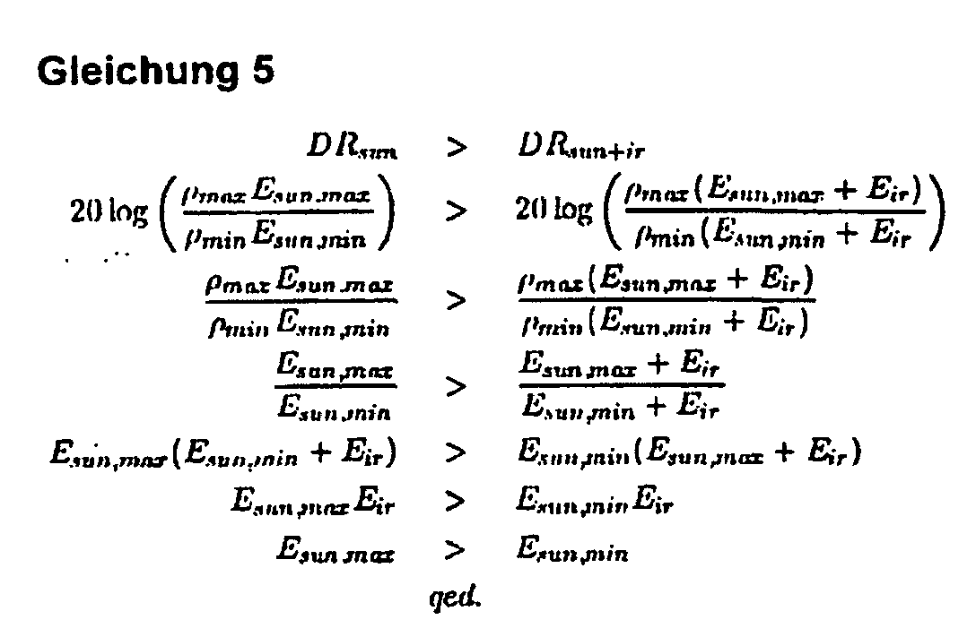
- E ir, low acts as a gain for the minimum light output E min , which was previously defined only by the extraneous light sources with E sun, min .
- E ir reduces the original dynamics of the scene.
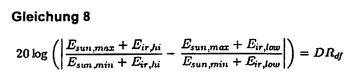
- the relationship between the intensity E ir, hi and E ir , low is shown in Equation 8.
- E ir, hi causes a higher dynamic reduction than E ir, low and thus also a lower contrast.
- the dynamics DR df of the output image is formed by the difference between the two self-illumination sources E ir, hi and E ir, low , since the extraneous light component has been eliminated by the offset suppression according to Equation 7.
- the output image of the double illumination should have a maximum contrast DR df of 1: 255, this corresponds to a dynamics of 48 dB or a linear pixel depth of 8 bits.
- the maximum camera dynamics of commercially available CMOS cameras has already been specified at 60 dB and thus resulted in a necessary self-lighting of 50 mW / m 2 .
- this necessary, minimum self-lighting is defined for reducing the dynamics of the scene with E ir, low .
- a stronger self-illumination E ir, hi leads only to a greater reduction in the dynamics of the scene and is thus definitely in the detection range of the camera.
- the irradiation intensities E sun, min and E sun, max occurring in a scene are given by the environmental influences and thus can not be controlled.
- the variation of E ir, low and E ir, hi the optical dynamics of a scene is influenced such that scenes with a really high dynamics DR sun can be analyzed by cameras with a lower optical dynamics DR df , without image information to lose, with simultaneous offset suppression.
- the speed of a CMOS camera is determined in the case of an automotive use without conditions such as video standards authoritative by the used integration time of the output current of the photodiodes.
- a camera that needs 10ms to expose to have a stable output at the pixels can not deliver images faster than those 10ms.
- OOP Out-Of-Position
- OOP detection can be carried out inexpensively by image processing even under the influence of strong extraneous light sources.
- the image preprocessing described last could already take place in the image sensor, to the calculation of the offset-free and low-dynamic output image accelerate. This has an increase in the speed of the overall system result.
Landscapes
- Engineering & Computer Science (AREA)
- Physics & Mathematics (AREA)
- General Physics & Mathematics (AREA)
- Multimedia (AREA)
- Theoretical Computer Science (AREA)
- Electromagnetism (AREA)
- Remote Sensing (AREA)
- Radar, Positioning & Navigation (AREA)
- Artificial Intelligence (AREA)
- Computer Vision & Pattern Recognition (AREA)
- Computer Networks & Wireless Communication (AREA)
- Signal Processing (AREA)
- Studio Devices (AREA)
- Image Processing (AREA)
Description
- Die verwendete Kamera kann den gesamten optischen Dynamikbereich der Szene erfassen und geht auch bei einzelnen Pixeln oder Bildbereichen nicht in die Sättigung (Übersteuerung/Untersteuerung).
- Die externe Bestrahlungsstärke Esun ändert sich zwischen den beiden Bildern nicht (andernfalls würde die Subtraktion der beiden Eingangsbilder ein unbrauchbares Ergebnis liefern)
- Die gesamte zu analysierende Szenerie unterliegt der Eigenbeleuchtung, wie dies in geschlossenen Räumen wie z.B. im Fahrzeug gegeben ist.
- Die Kennlinie des Bildsensors ist vorzugsweise linear. Dadurch verringert sich der Aufwand für die Differenzbildung der beiden Eingangsbilder. Die Subtraktion zweier Bilder einer Kamera mit logarithmischer Kennlinie ist gleichbedeutend mit einer Division der Grauwerte und somit ungeeignet. Es besteht jedoch die Möglichkeit das Ausgangssignal eines logarithmischen Bildsensors durch eine Look-Up Table zu linearisieren, um im Anschluss die Bilder zu subtrahieren.

Hierdurch sind größere Impulsströme und somit mehr Lichtleistung bei gleichzeitig kleineren Leuchtdioden möglich.

Bildrate zu erhöhen. Gerade die OOP (Out-Of-Position) Anwendung stellt sehr kritische Zeitanforderungen, die im Moment von einer HDR-Kamera prinzipbedingt nicht erfüllt werden kann. Durch die Reduzierung der optischen Dynamik im Innenraum eines Fahrzeugs kann eine OOP-Erkennung mittels Bildverarbeitung kostengünstig selbst beim Einfluß von starken Fremdlichtquellen durchgeführt werden.
Claims (3)
- Verfahren zur Überwachung des Innenraums eines Kraftfahrzeuges mittels IR-Strahlung, bei dem mindestens ein stationärer IR-Sender und mindestens ein stationärer IR-Empfänger in zentraler Position im Fahrzeuginnenraum angeordnet ist, der Innenraum zumindest temporär bestrahlt wird, die reflektierte IR-Strahlung mit einer IR-Kamera als IR-Empfänger empfangen wird, dass zur Unterdrückung von Störeinflüssen zwei Bilder aufgenommen werden, und die beiden Bilder hinsichtlich ihrer Grauwerte voneinander subtrahiert werden, dadurch gekennzeichnet, dass es zwei Bilder desselben Objekts sind, die durch eine Beleuchtung des mindestens einen IR-Sensors mit zwei verschiedenen Licht-Ausgangsleistungen des IR-Senders erzeugt werden und die Beleuchtungsstärken so gewählt werden, dass deren Unterschied unter Ausblendung des Umgebungslichtes den vollen Dynamikbereich der Kamera ausnutzt.
- Verfahren nach Anspruch 1, dadurch gekennzeichnet, dass der IR-Sender eine Leuchtdiode ist, die während der Integrationszeit des IR-Sensors eingeschaltet und während der Read-Out Phase des IR-Sensors ausgeschaltet ist.
- Verfahren nach einem der Ansprüche 1 oder 2, dadurch gekennzeichnet, dass das optische Sensorelement der Kamera eine lineare Kennlinie besitzt, oder dass Kameras mit einer nicht-linearen Kennlinie mittels einer Look-Up Table einen linearen Ausgang zur Verfügung stellen.
Applications Claiming Priority (2)
| Application Number | Priority Date | Filing Date | Title |
|---|---|---|---|
| DE10062977A DE10062977A1 (de) | 2000-12-16 | 2000-12-16 | Verfahren zur Überwachung des Innenraums eines Kraftfahrzeuges |
| DE10062977 | 2000-12-16 |
Publications (2)
| Publication Number | Publication Date |
|---|---|
| EP1215619A1 EP1215619A1 (de) | 2002-06-19 |
| EP1215619B1 true EP1215619B1 (de) | 2005-03-23 |
Family
ID=7667576
Family Applications (1)
| Application Number | Title | Priority Date | Filing Date |
|---|---|---|---|
| EP01127922A Expired - Lifetime EP1215619B1 (de) | 2000-12-16 | 2001-11-23 | Verfahren zur Überwachung des Innenraums eines Kraftfahrzeuges |
Country Status (4)
| Country | Link |
|---|---|
| US (1) | US6674079B2 (de) |
| EP (1) | EP1215619B1 (de) |
| DE (2) | DE10062977A1 (de) |
| ES (1) | ES2236118T3 (de) |
Families Citing this family (5)
| Publication number | Priority date | Publication date | Assignee | Title |
|---|---|---|---|---|
| DE10245912B4 (de) * | 2002-10-01 | 2011-12-08 | Bayerische Motoren Werke Aktiengesellschaft | Verfahren zum Betreiben einer optoelektronischen Sensorvorrichtung |
| DE10250705A1 (de) * | 2002-10-31 | 2004-05-13 | Bayerische Motoren Werke Ag | Verfahren und Vorrichtung zur Schattenkompensation in digitalen Bildern |
| US7599576B2 (en) * | 2004-01-23 | 2009-10-06 | Electro Scientific Industries, Inc. | Image subtraction of illumination artifacts |
| JP2006259900A (ja) * | 2005-03-15 | 2006-09-28 | Omron Corp | 画像処理システム、画像処理装置および方法、記録媒体、並びにプログラム |
| JP4797752B2 (ja) * | 2006-03-31 | 2011-10-19 | 株式会社デンソー | 移動体用操作物体抽出装置 |
Family Cites Families (12)
| Publication number | Priority date | Publication date | Assignee | Title |
|---|---|---|---|---|
| US5500904A (en) * | 1992-04-22 | 1996-03-19 | Texas Instruments Incorporated | System and method for indicating a change between images |
| DE4228629C2 (de) * | 1992-08-28 | 1994-12-15 | Dornier Gmbh | Bildaufnahme- und Bildverarbeitungssystem zur nächtlichen Videoüberwachung |
| KR940008510A (ko) * | 1992-09-14 | 1994-04-29 | 김광호 | 고체촬상소자(ccd)형 컬러비디오카메라의 비디오신호처리회로 |
| DE4417710C2 (de) * | 1994-03-01 | 1996-01-25 | Becker Gmbh | Infrarot-Innenraumüberwachungs-System |
| US5631976A (en) * | 1994-04-29 | 1997-05-20 | International Business Machines Corporation | Object imaging system |
| US6028672A (en) * | 1996-09-30 | 2000-02-22 | Zheng J. Geng | High speed three dimensional imaging method |
| DE19532680A1 (de) | 1995-09-05 | 1997-03-06 | Telefunken Microelectron | Optisches System |
| US5909244A (en) * | 1996-04-15 | 1999-06-01 | Massachusetts Institute Of Technology | Real time adaptive digital image processing for dynamic range remapping of imagery including low-light-level visible imagery |
| DE29617749U1 (de) * | 1996-10-12 | 1997-01-23 | Schoenberger Armin | Überwachungsvorrichtung |
| DE19736584A1 (de) * | 1997-08-22 | 1999-02-25 | Kostal Leopold Gmbh & Co Kg | Verfahren zum Erkennen von Veränderungen im Innenraum eines Kraftfahrzeuges sowie ein Innenraumüberwachungssystem für ein Kraftfahrzeug |
| US6021210A (en) * | 1997-12-01 | 2000-02-01 | Sensar, Inc. | Image subtraction to remove ambient illumination |
| DE19921488A1 (de) * | 1999-05-08 | 2000-11-16 | Bosch Gmbh Robert | Verfahren und Vorrichtung zur Überwachung des Innenraums und des Umfeldes eines Fahrzeugs |
-
2000
- 2000-12-16 DE DE10062977A patent/DE10062977A1/de not_active Withdrawn
-
2001
- 2001-11-23 ES ES01127922T patent/ES2236118T3/es not_active Expired - Lifetime
- 2001-11-23 EP EP01127922A patent/EP1215619B1/de not_active Expired - Lifetime
- 2001-11-23 DE DE50105679T patent/DE50105679D1/de not_active Expired - Lifetime
- 2001-12-17 US US10/015,945 patent/US6674079B2/en not_active Expired - Lifetime
Also Published As
| Publication number | Publication date |
|---|---|
| DE10062977A1 (de) | 2002-06-27 |
| ES2236118T3 (es) | 2005-07-16 |
| US20020113209A1 (en) | 2002-08-22 |
| EP1215619A1 (de) | 2002-06-19 |
| US6674079B2 (en) | 2004-01-06 |
| DE50105679D1 (de) | 2005-04-28 |
Similar Documents
| Publication | Publication Date | Title |
|---|---|---|
| EP1019267B1 (de) | Verfahren und anordnung zur ermittlung der lichtverhältnisse in front eines fahrzeugs | |
| DE102019114533A1 (de) | Erkennung von visible-light-communication-quellen über einen hohen dynamikbereich | |
| KR20070005553A (ko) | 촬상시스템 | |
| JP4985394B2 (ja) | 画像処理装置および方法、プログラム、並びに記録媒体 | |
| DE10303046A1 (de) | Verfahren und Vorrichtung zur quantitativen Abschätzung der Sichtweite in Fahrzeugen | |
| DE102011088393A1 (de) | Bestimmen einer Gesamtzahl an Personen in einem IR-Bild, das mittels eines IR-Bilderzeugungssystems gewonnen wird | |
| EP2879919B1 (de) | Detektion von regentropfen auf einer scheibe mittels einer kamera und beleuchtung | |
| DE102018207388B4 (de) | Verfahren und Vorrichtung zur Erzeugung eines Anzeigebildes in einem Kraftfahrzeug | |
| DE102014013099A1 (de) | Verfahren und Vorrichtung zur vereinfachten Erfassung eines Tiefenbildes | |
| WO2007009836A1 (de) | Bildaufnahmesystem | |
| DE102004010908B4 (de) | Bildaufnahmevorrichtung und Bildaufnahmeverfahren | |
| DE102009055269A1 (de) | Verfahren zur Bestimmung der Relativbewegung mittels einer HDR-Kamera | |
| DE102012216065A1 (de) | Verfahren und Vorrichtung zur Erkennung von zumindest einer gepulsten Lichtquelle für ein Fahrzeug | |
| DE69223625T2 (de) | Elektro-optischer detektor für reflexfreie unterwasseraufnahmen aus der luft | |
| EP3100594A1 (de) | Selbstjustierender sensor zum erfassen des tageslichts | |
| EP2978216B1 (de) | Verfahren zur Erkennung von Bewegungsunschärfe | |
| EP1476326B1 (de) | Einrichtung zur automatischen einstellung der leuchtdichte des von einer rückwärtigen beleuchtungseinrichtung eines fahrzeugs ausgesandten lichtbündels | |
| EP1215619A1 (de) | Verfahren zur Überwachung des Innenraums eines Kraftfahrzeuges | |
| DE102006055905A1 (de) | Verfahren zur Fahrzeugumfelderkennung und Vorrichtung zur Umfelderkennung in einem Kraftfahrzeug | |
| DE1537952A1 (de) | Bildwiedergabe- bzw. Fernsehsystem | |
| DE102016114419B3 (de) | Messverfahren, Sensorfeld und Messsystem mit lokalen lichtemittierenden Sensoren | |
| DE102004042816B3 (de) | Nachtsichtsystem für ein Kraftfahrzeug | |
| DE10126683A1 (de) | Nachtsichteinrichtung für Fahrzeuge | |
| EP1829373B1 (de) | Vorrichtung zur umgebungslicht-unabhängigen kontinuierlichen beobachtung von objekten | |
| DE102012108316A1 (de) | Detektion von Regentropfen auf einer Scheibe mittels einer Kamera und Beleuchtung |
Legal Events
| Date | Code | Title | Description |
|---|---|---|---|
| PUAI | Public reference made under article 153(3) epc to a published international application that has entered the european phase |
Free format text: ORIGINAL CODE: 0009012 |
|
| AK | Designated contracting states |
Kind code of ref document: A1 Designated state(s): AT BE CH CY DE DK ES FI FR GB GR IE IT LI LU MC NL PT SE TR |
|
| AX | Request for extension of the european patent |
Free format text: AL;LT;LV;MK;RO;SI |
|
| 17P | Request for examination filed |
Effective date: 20020702 |
|
| AKX | Designation fees paid |
Designated state(s): DE ES FR GB IT SE |
|
| 17Q | First examination report despatched |
Effective date: 20030417 |
|
| GRAP | Despatch of communication of intention to grant a patent |
Free format text: ORIGINAL CODE: EPIDOSNIGR1 |
|
| GRAS | Grant fee paid |
Free format text: ORIGINAL CODE: EPIDOSNIGR3 |
|
| GRAA | (expected) grant |
Free format text: ORIGINAL CODE: 0009210 |
|
| AK | Designated contracting states |
Kind code of ref document: B1 Designated state(s): DE ES FR GB IT SE |
|
| REG | Reference to a national code |
Ref country code: GB Ref legal event code: FG4D Free format text: NOT ENGLISH |
|
| GBT | Gb: translation of ep patent filed (gb section 77(6)(a)/1977) |
Effective date: 20050323 |
|
| REG | Reference to a national code |
Ref country code: IE Ref legal event code: FG4D Free format text: GERMAN |
|
| REF | Corresponds to: |
Ref document number: 50105679 Country of ref document: DE Date of ref document: 20050428 Kind code of ref document: P |
|
| REG | Reference to a national code |
Ref country code: SE Ref legal event code: TRGR |
|
| REG | Reference to a national code |
Ref country code: ES Ref legal event code: FG2A Ref document number: 2236118 Country of ref document: ES Kind code of ref document: T3 |
|
| ET | Fr: translation filed | ||
| PLBE | No opposition filed within time limit |
Free format text: ORIGINAL CODE: 0009261 |
|
| STAA | Information on the status of an ep patent application or granted ep patent |
Free format text: STATUS: NO OPPOSITION FILED WITHIN TIME LIMIT |
|
| 26N | No opposition filed |
Effective date: 20051227 |
|
| REG | Reference to a national code |
Ref country code: FR Ref legal event code: PLFP Year of fee payment: 15 |
|
| REG | Reference to a national code |
Ref country code: FR Ref legal event code: PLFP Year of fee payment: 16 |
|
| REG | Reference to a national code |
Ref country code: FR Ref legal event code: PLFP Year of fee payment: 17 |
|
| PGFP | Annual fee paid to national office [announced via postgrant information from national office to epo] |
Ref country code: IT Payment date: 20201130 Year of fee payment: 20 Ref country code: ES Payment date: 20201214 Year of fee payment: 20 Ref country code: FR Payment date: 20201119 Year of fee payment: 20 Ref country code: DE Payment date: 20201126 Year of fee payment: 20 Ref country code: SE Payment date: 20201123 Year of fee payment: 20 Ref country code: GB Payment date: 20201123 Year of fee payment: 20 |
|
| REG | Reference to a national code |
Ref country code: DE Ref legal event code: R071 Ref document number: 50105679 Country of ref document: DE |
|
| REG | Reference to a national code |
Ref country code: GB Ref legal event code: PE20 Expiry date: 20211122 |
|
| REG | Reference to a national code |
Ref country code: SE Ref legal event code: EUG |
|
| PG25 | Lapsed in a contracting state [announced via postgrant information from national office to epo] |
Ref country code: GB Free format text: LAPSE BECAUSE OF EXPIRATION OF PROTECTION Effective date: 20211122 |
|
| REG | Reference to a national code |
Ref country code: ES Ref legal event code: FD2A Effective date: 20220406 |
|
| PG25 | Lapsed in a contracting state [announced via postgrant information from national office to epo] |
Ref country code: ES Free format text: LAPSE BECAUSE OF EXPIRATION OF PROTECTION Effective date: 20211124 |
|
| P01 | Opt-out of the competence of the unified patent court (upc) registered |
Effective date: 20230502 |