EP1215373A2 - Abgasreinigungsanlage zum Entsticken von Abgasen einer Brennkraftmaschine - Google Patents
Abgasreinigungsanlage zum Entsticken von Abgasen einer Brennkraftmaschine Download PDFInfo
- Publication number
- EP1215373A2 EP1215373A2 EP01128290A EP01128290A EP1215373A2 EP 1215373 A2 EP1215373 A2 EP 1215373A2 EP 01128290 A EP01128290 A EP 01128290A EP 01128290 A EP01128290 A EP 01128290A EP 1215373 A2 EP1215373 A2 EP 1215373A2
- Authority
- EP
- European Patent Office
- Prior art keywords
- exhaust gas
- reduction
- container
- docking device
- tank
- Prior art date
- Legal status (The legal status is an assumption and is not a legal conclusion. Google has not performed a legal analysis and makes no representation as to the accuracy of the status listed.)
- Granted
Links
Images


Classifications
-
- F—MECHANICAL ENGINEERING; LIGHTING; HEATING; WEAPONS; BLASTING
- F01—MACHINES OR ENGINES IN GENERAL; ENGINE PLANTS IN GENERAL; STEAM ENGINES
- F01N—GAS-FLOW SILENCERS OR EXHAUST APPARATUS FOR MACHINES OR ENGINES IN GENERAL; GAS-FLOW SILENCERS OR EXHAUST APPARATUS FOR INTERNAL-COMBUSTION ENGINES
- F01N3/00—Exhaust or silencing apparatus having means for purifying, rendering innocuous, or otherwise treating exhaust
- F01N3/08—Exhaust or silencing apparatus having means for purifying, rendering innocuous, or otherwise treating exhaust for rendering innocuous
- F01N3/10—Exhaust or silencing apparatus having means for purifying, rendering innocuous, or otherwise treating exhaust for rendering innocuous by thermal or catalytic conversion of noxious components of exhaust
- F01N3/18—Exhaust or silencing apparatus having means for purifying, rendering innocuous, or otherwise treating exhaust for rendering innocuous by thermal or catalytic conversion of noxious components of exhaust characterised by methods of operation; Control
- F01N3/20—Exhaust or silencing apparatus having means for purifying, rendering innocuous, or otherwise treating exhaust for rendering innocuous by thermal or catalytic conversion of noxious components of exhaust characterised by methods of operation; Control specially adapted for catalytic conversion
- F01N3/206—Adding periodically or continuously substances to exhaust gases for promoting purification, e.g. catalytic material in liquid form, NOx reducing agents
- F01N3/2066—Selective catalytic reduction [SCR]
-
- B—PERFORMING OPERATIONS; TRANSPORTING
- B01—PHYSICAL OR CHEMICAL PROCESSES OR APPARATUS IN GENERAL
- B01D—SEPARATION
- B01D53/00—Separation of gases or vapours; Recovering vapours of volatile solvents from gases; Chemical or biological purification of waste gases, e.g. engine exhaust gases, smoke, fumes, flue gases, aerosols
- B01D53/34—Chemical or biological purification of waste gases
- B01D53/92—Chemical or biological purification of waste gases of engine exhaust gases
- B01D53/94—Chemical or biological purification of waste gases of engine exhaust gases by catalytic processes
- B01D53/9404—Removing only nitrogen compounds
- B01D53/9409—Nitrogen oxides
- B01D53/9431—Processes characterised by a specific device
-
- B—PERFORMING OPERATIONS; TRANSPORTING
- B01—PHYSICAL OR CHEMICAL PROCESSES OR APPARATUS IN GENERAL
- B01D—SEPARATION
- B01D53/00—Separation of gases or vapours; Recovering vapours of volatile solvents from gases; Chemical or biological purification of waste gases, e.g. engine exhaust gases, smoke, fumes, flue gases, aerosols
- B01D53/34—Chemical or biological purification of waste gases
- B01D53/92—Chemical or biological purification of waste gases of engine exhaust gases
- B01D53/94—Chemical or biological purification of waste gases of engine exhaust gases by catalytic processes
- B01D53/9495—Controlling the catalytic process
-
- F—MECHANICAL ENGINEERING; LIGHTING; HEATING; WEAPONS; BLASTING
- F01—MACHINES OR ENGINES IN GENERAL; ENGINE PLANTS IN GENERAL; STEAM ENGINES
- F01N—GAS-FLOW SILENCERS OR EXHAUST APPARATUS FOR MACHINES OR ENGINES IN GENERAL; GAS-FLOW SILENCERS OR EXHAUST APPARATUS FOR INTERNAL-COMBUSTION ENGINES
- F01N2330/00—Structure of catalyst support or particle filter
- F01N2330/02—Metallic plates or honeycombs, e.g. superposed or rolled-up corrugated or otherwise deformed sheet metal
- F01N2330/04—Methods of manufacturing
-
- F—MECHANICAL ENGINEERING; LIGHTING; HEATING; WEAPONS; BLASTING
- F01—MACHINES OR ENGINES IN GENERAL; ENGINE PLANTS IN GENERAL; STEAM ENGINES
- F01N—GAS-FLOW SILENCERS OR EXHAUST APPARATUS FOR MACHINES OR ENGINES IN GENERAL; GAS-FLOW SILENCERS OR EXHAUST APPARATUS FOR INTERNAL-COMBUSTION ENGINES
- F01N2610/00—Adding substances to exhaust gases
- F01N2610/02—Adding substances to exhaust gases the substance being ammonia or urea
-
- F—MECHANICAL ENGINEERING; LIGHTING; HEATING; WEAPONS; BLASTING
- F01—MACHINES OR ENGINES IN GENERAL; ENGINE PLANTS IN GENERAL; STEAM ENGINES
- F01N—GAS-FLOW SILENCERS OR EXHAUST APPARATUS FOR MACHINES OR ENGINES IN GENERAL; GAS-FLOW SILENCERS OR EXHAUST APPARATUS FOR INTERNAL-COMBUSTION ENGINES
- F01N2610/00—Adding substances to exhaust gases
- F01N2610/06—Adding substances to exhaust gases the substance being in the gaseous form
-
- F—MECHANICAL ENGINEERING; LIGHTING; HEATING; WEAPONS; BLASTING
- F01—MACHINES OR ENGINES IN GENERAL; ENGINE PLANTS IN GENERAL; STEAM ENGINES
- F01N—GAS-FLOW SILENCERS OR EXHAUST APPARATUS FOR MACHINES OR ENGINES IN GENERAL; GAS-FLOW SILENCERS OR EXHAUST APPARATUS FOR INTERNAL-COMBUSTION ENGINES
- F01N2610/00—Adding substances to exhaust gases
- F01N2610/14—Arrangements for the supply of substances, e.g. conduits
- F01N2610/1406—Storage means for substances, e.g. tanks or reservoirs
-
- Y—GENERAL TAGGING OF NEW TECHNOLOGICAL DEVELOPMENTS; GENERAL TAGGING OF CROSS-SECTIONAL TECHNOLOGIES SPANNING OVER SEVERAL SECTIONS OF THE IPC; TECHNICAL SUBJECTS COVERED BY FORMER USPC CROSS-REFERENCE ART COLLECTIONS [XRACs] AND DIGESTS
- Y02—TECHNOLOGIES OR APPLICATIONS FOR MITIGATION OR ADAPTATION AGAINST CLIMATE CHANGE
- Y02T—CLIMATE CHANGE MITIGATION TECHNOLOGIES RELATED TO TRANSPORTATION
- Y02T10/00—Road transport of goods or passengers
- Y02T10/10—Internal combustion engine [ICE] based vehicles
- Y02T10/12—Improving ICE efficiencies
Definitions
- the invention relates to an exhaust gas purification system for the denitrification of exhaust gases from an internal combustion engine on an SCR catalytic converter using ammonia (NH 3 ) additionally introduced into the exhaust gas stream upstream of the SCR catalytic converter, comprising a reduction tank in which the NH 3 to be supplied to the exhaust gas stream is stored. which reduction tank is connected to the exhaust line via a supply line. Furthermore, the invention relates to a device for holding and connecting a reduction container in the context of an interchangeable container system to such an exhaust gas cleaning system. The invention further relates to a container for ammonia for use in such an exhaust gas cleaning system.
- NH 3 ammonia
- nitrogen oxides (NO x ) in particular are among the environmentally hazardous, directly emitted primary pollutants that arise from the operation of internal combustion engines, especially diesel engines.
- a selectively operating SCR catalyst S elective C atalytic R eduction catalyst
- NH 3 ammonia
- Such exhaust gas cleaning systems are known, for example, from EP 0 277 765 A1 or EP 0 381 276 A1.
- the NH 3 is stored as a liquid in a pressure-resistant container and connected to the exhaust line via a supply line.
- the gaseous NH 3 is tapped from the reduction tank and is injected into the exhaust gas flow in the required quantity via a metering valve controlled by a control unit. A quantity is metered depending on the current operating conditions of the internal combustion engine.
- the invention lies on the basis of this prior art discussed therefore based on the task of a generic type mentioned Exhaust gas cleaning system in such a way that the to stand the disadvantages shown in the art are minimized, if not avoided are.
- the at least one reduction tank in a docking device as part of the Exhaust gas cleaning system held and with a coupling device the supply line is connected by which coupling device one coupling part of the docking device and the other coupling part is assigned to the reduction tank, both coupling parts via an axial, mutually directed movement with each other are engaged, and the docking device and the at least have a reducing container interacting guide means, through which the at least one reduction vessel is guided into its Intended position to bring the two coupling parts together is feasible.
- the object is achieved by a device for holding and connecting a reduction tank as part of a swap body system to an exhaust gas cleaning system mentioned at the outset, which is determined by the characterizing features of claim 24. Furthermore, this task is accomplished by a reduction tank Use in an exhaust gas cleaning system with the Features of claim 25 solved.
- the exhaust gas cleaning system comprises a docking device to hold one or more reduction tanks.
- This Docking device has a coupling part, which can be created a fluid connection between the reduction tank and the Supply line with a second, assigned to the reduction tank Coupling part is adjustable in engagement.
- the two coupling parts are designed in the manner of a quick coupling and at least partially over an axial, mutually directed movement in engagement with each other to deliver. It can therefore be sufficient to connect the two coupling parts be the two coupling parts axially towards each other move until the intended connection is finally established is. It can also be provided that the axial movement only a vector part of a merging movement of the two Represents coupling parts, in which also contain a rotary part is.
- the two coupling parts can, for example be engaged by a bayonet.
- the docking device further comprises guide means through which a reduction tank in its intended position to bring the two together Coupling parts can be brought.
- the guide means can be such Include means for guiding and supporting the reduction container serve as such and also have guide means provided are to the two coupling parts as intended with each other To intervene.
- an exhaust gas cleaning system equipped with such a docking device can not only a quick change of the reduction tank used take place, but in particular can be used by the Guide means or the reduction container to the supply line be connected without having to merge immediately of the coupling parts someone lead the coupling parts themselves got to.
- a reduction container can thus be in the docking device be connected to the emission control system in which the reduction tank at its end opposite the coupling part - the bottom of the vessel - is handled and the container change performing person thus at a relatively large distance from the two coupling parts to be engaged with each other.
- a reduction tank for such an exhaust gas purification system at its foot end opposite the coupling part a handle for handling the reduction tank.
- the bottom of the reduction container can be handled surrounding ring with handle openings inserted therein.
- the purpose of the reduction containers in the docking device is expedient kept lying down.
- the exhaust gas purification system comprises guide means for engaging of the two coupling parts with each other, in the manner of a bayonet lock are formed, it is expedient to each concentrically to provide mutually arranged annular bodies, the reduction container such a concentrically the associated coupling part surrounding ring body with one or more introduced therein Bayonet grooves open on the top and another ring body concentric to the coupling part assigned to the docking device with a number of guide pins corresponding to the number of bayonet grooves assigned.
- the use of such a bayonet lock between the reduction tank and the docking device provides a guided movement with which both an axial stroke and also a rotational movement of the two coupling parts against each other is exercisable.
- the guide grooves used have no slope in a last section, which is then useful if such a clutch is used, at the one after creating the intended connection by a final one rotational movement of the two coupling parts against each other an actual opening to create the desired fluid connection he follows.
- the or the reduction container used in the docking device additionally locked by a locking device are to the reduction container used in the docking device to back up.
- a locking device it is expedient to To provide means that only then a closing of the locking device allow if the or the inserted into the docking device Reduction tanks are arranged as intended.
- Such additional security can be realized, for example, by that the locking device is pivotable on the docking device has articulated locking arm, each in the docking device used reduction container such a locking arm assigned. Also located on the locking arm Extensions that with a proper positioning of the Locking arm assigned reduction container in corresponding Engage openings or recesses in the reduction tank. at Use of a reduction tank described above with one on the bottom located handle can such openings in, for example the lower edge of the handle.
- the exhaust gas cleaning system can be designed to remove NH 3 in its gaseous or in its liquid phase either from a reduction tank. It can be provided that both NH 3 is contained in the reducing agent container in pure form or also in a mixed form or also bound, from which chemical compound it can be thermolytically split off. If the exhaust gas purification system is designed to remove NH 3 gas from the reduction tank, it is expedient to assign a heat source to the docking device, which is designed and arranged in such a way that only a partial area of each reduction tank or its contents can be heated by the heat source.
- the heat source is designed and arranged in such a way that only a portion of the reduction vessel or its contents can be heated by the heat source, and expediently such a portion of the reduction vessel in which the liquid NH 3 is located until it is emptied. This is usually the deepest of the reduction tank.
- the heating of a partial area of the reduction tank is particularly simple in its implementation, since for this purpose only a smaller amount of heat is required and, in a particularly clever manner, the convection of the liquid NH 3 that occurs in the reduction tank during local warming and that due to local boiling Turbulence occurring in the formation of vapor bubbles can be used for heat distribution within the liquid contained in the reduction tank. With this emission control system, it is therefore not necessary to heat the entire reduction tank. In addition, when a heat source that only causes local heating is used, a control circuit that responds much more quickly can be formed.
- the heat source can be used, for example, as resistance heating or as PTC element arranged on the surface of the reduction tank his.
- the heat source is designed in order to heat the contents of the reduction tank from outside without contact.
- the advantage of such a non-contact heating of its contents with respect to the reduction container is that the reduction container can then be exchanged in a simple manner within the scope of the exchange system described using the docking device after it has been emptied and can be replaced by a filled one without any additional retrofitting or installation the heat source must be made.
- a non-contact heat source for example, one can be provided which emits high-energy radiation, only a partial area of the reduction container - the local heating point - being located within the radiation of the heat source.
- the heat source can, for example, be designed to emit IR radiation, it being expedient in such an embodiment to provide the local heating point of the reduction container in a particularly radiation-adsorbent manner, for example blackened.
- a transmitter for emitting microwave radiation as high-energy radiation can also be used as the heat source for heating the liquid NH 3 .
- a sub-area of the reduction container can also be irradiated or subjected to heat by several individual heat sources.
- the handle is made of a material with only a low thermal conductivity, such as plastic.
- a liquid trap downstream of the outlet of the reducing agent container, so that liquid which escapes when the reducing agent container is changed is caught in the liquid trap and does not penetrate into the further system.
- a liquid trap may further comprise a heater to be assigned to be able to evaporate the trapped in the liquid trap NH 3 and to supply the NH 3 in its gaseous phase provided for exhaust gas purification.
- the exhaust gas cleaning system is designed to remove NH 3 in its liquid phase from the reduction tank, it is expedient that a metering device is connected downstream of the removal device in the direction of flow of the NH 3 into the supply line, and an evaporator is connected downstream of the metering device before the Supply line opens into the exhaust line.
- the reduction container has a removal device for removing liquid NH 3 , which can be designed, for example, in the manner of a proboscis. Liquid ammonia can enter such a removal nozzle by the vapor pressure in the reduction tank or by a suction device.
- the removal device for removing liquid NH 3 from the reduction tank is followed by a metering device, for example a metering valve, by means of which the amount of NH 3 required in each case is removed from the reduction tank.
- a metering device Downstream of the metering device is an evaporator for evaporating the NH 3 removed from the reduction tank by the metering device. It can be provided that the metering device delivers clocked or continuously NH 3 to the evaporator to the extent required.
- the liquid NH 3 is evaporated in the evaporator in order to be able to inject NH 3 in the gaseous state into the exhaust line.
- the liquid NH 3 is only evaporated in such an amount that is currently also required in the exhaust line to carry out the desired denitrification. Therefore, it is fundamentally not necessary to design the evaporator used in such a way that it also serves as a storage container for a larger gaseous amount of NH 3 , from which the amount required for injection into the exhaust line is then removed. As a result, the necessary safety requirements for the evaporator are kept to a minimum.
- a device for preventing or preventing the escape of liquid NH 3 is arranged at the outlet of the evaporator.
- a liquid barrier can be implemented, for example, by a float valve which closes as soon as liquid is present at the outlet of the evaporator.
- a filter element can also be provided which, although gaseous NH 3 , allows no or only very little liquid NH 3 to pass through.
- a float valve When using a float valve, it is expedient to design it with appropriate sensors or switches so that the position of the float can be detected for a control device. If the system recognizes that the float valve is closed, which means that liquid NH 3 is present at the outlet of the evaporator, an emergency valve can be closed, for example, or the evaporator can be started to convert the liquid NH 3 into its gaseous and to bring less safety-relevant phase. Likewise, such a locking device equipped with sensors can also directly switch the evaporator.
- the evaporator is connected downstream an air supply device through which the reduction vessel additional air with the supply line connecting the exhaust line is supplied, this air supplied both in constant operation the exhaust gas cleaning system to increase the transport speed of the gas produced in the evaporator in the exhaust line and / or can be used to flush the supply line.
- air supply device through which the reduction vessel additional air with the supply line connecting the exhaust line is supplied, this air supplied both in constant operation the exhaust gas cleaning system to increase the transport speed of the gas produced in the evaporator in the exhaust line and / or can be used to flush the supply line.
- a motor vehicle, not shown, with a diesel engine shows an SCR catalytic converter 2 inserted in the exhaust line 1.
- An exhaust gas cleaning system 3 is assigned to the exhaust line 1, via which the exhaust gases produced by the internal combustion engine upstream of the exhaust line 1 are removed before the SCR catalytic converter 2 Reducing agent NH 3 is supplied.
- the essential components of the exhaust gas cleaning system 3 in the exemplary embodiment shown consist of a reduction tank 4 filled with liquid ammonia (NH 3 ) 5.
- the reduction tank 4 is therefore designed to be pressure-resistant in order to be able to withstand the vapor pressure generated when the NH 3 is gasified.
- the exhaust gas cleaning system 3 is designed to remove liquid NH 3 from the reduction tank 4.
- a removal nozzle 6 is arranged in the reduction container 4, which extends into the deepest part of the reduction container 4.
- the reduction tank 4 is provided lying down; in the event that the reduction container is arranged upright in the motor vehicle, the removal nozzle extends into the area of its base.
- the reduction tank 4 is connected via a coupling system to a supply line 7 for supplying the gaseous ammonia into the exhaust line 1.
- a metering valve 8 is switched into the supply line 7 before the supply line 7 opens into the exhaust line 1.
- the metering valve 8 is connected to a control device 9, which is supplied with parameters, reflecting the current engine operating state, so that the NH 3 quantity to be supplied can be calculated from these parameters.
- evaporator 10 Downstream of the metering valve 8 is an evaporator 10 for evaporating the amount of NH 3 removed from the reduction tank 4 by the metering valve 8.
- the evaporator 10 is also connected to the control device 9, for example an engine management system, by means of which the evaporator can be switched and regulated in its different states.
- a float valve 11 At the outlet of the evaporator 10, a float valve 11 is switched into the supply line 7, by means of which a liquid barrier is implemented at the outlet of the evaporator 10.
- a liquid barrier is implemented at the outlet of the evaporator 10.
- the float valve 11 closes so that liquid NH 3 is prevented from escaping when the metering valve 8 is open and the evaporator 10 is not working.
- the float valve 11 is also connected to the control device 9, via which the position of the float is detected, so that when a closed float valve 11 is detected, appropriate actions can be triggered by the control device 9.
- the air supply device 12 Downstream of the float valve 11 is the mouth of an air supply device, identified overall by reference numeral 12, through which additional air is added to the remaining section of the supply line 7 between the air supply device 12 and the exhaust line 1.
- the air supply device 12 comprises a clock valve 13 and an air source 14 which, when used, the exhaust gas cleaning system 3 can be the air tank in a motor vehicle with a compressed air brake.
- the additionally supplied air serves on the one hand to increase the transport speed of the liquid NH 3 gasified by the evaporator 10 on the remaining path to the exhaust line 1.
- the supply line can be used to clean or purge the supply line.
- the reduction tanks 4 are pressure-resistant tanks formed and have a cylindrical outer surface.
- the two opposite floors B of such a reduction tank 4 are convex.
- To such a reduction tank 4 better Handling and stacking are handled at both ends 17, 18 arranged as ring elements, in each of the handle openings G are introduced.
- the docking device 15 comprises a frame 19 in which each reduction container 4 four guide rods F are assigned, which are in the same Angular distance from each other on the outer surface of a reduction tank issue.
- guide rails or the like may also be provided.
- guide rods F are used to guide and hold an inserted reduction tank.
- the lower reduction tank 4 shown in Figure 2 is already inserted in the docking device 15 and with the supply line been put in fluid communication.
- the frame 19 is regarding its length designed so that the rear handle 17 of the reduction tank 4 protrudes out of the frame 19, so that the reduction container 4 inserting or changing person without further ado can take the handle 17 to the reduction tank 4 through Initiate a rotational movement from the supply line to separate and then pull out of the frame 19 to can.
- Figure 3 again shows such a reduction tank 4, but in Difference to the representation of Figure 2 with a view of the head end and the upper floor B.
- a coupling part 20 is central and arranged protruding from the bottom B, which with another the coupling device 15 associated coupling part can.
- the coupling part 20 is concentric of an annular body 21 surrounded, which, as explained below, for guidance in manufacturing serves the fluid connection.
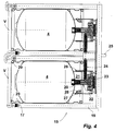
- the two reduction containers 4 inserted into the docking device 15 are shown in the sectional view in FIG. Both reduction vessels 4 are connected with their coupling part 20 to a second coupling part 22 assigned to the docking device 15 or are brought into engagement with it.
- the second coupling part 22 is arranged in a floating manner on the frame 19 with respect to the frame 19 in order to prevent the introduction of voltages due to possible vibrations of the reduction container 4 into the supply line 7 and aggregates connected therein.
- the rear attachment is made via a rubber bed 23; the liquid connection to the actual supply line takes place via a hose 24 or, for example, a coiled tubing.
- the units necessary for removal, the metering valve 8, the evaporator 10 and the float valve 11 and the clock valve 13 of the air supply device 12 are also arranged. For the sake of clarity, these units are not shown in FIG. 4.
- the docking device 15 has an NH 3 outlet 25 as part of the supply line 7, which opens into the exhaust line 1.
- Coupling part 22 serves the ring body 21 as a guide, which in one engages second coupling part 22 associated second ring body 26.
- This second ring body 26 carries guide pins 27, of which in the Figure only one is shown.
- the guide pins 27 each grip into a bayonet groove introduced into the annular body 21 of the reduction container 4 28 a. After engagement of the two ring bodies 21, 26 and of the guide pin 27 in the bayonet groove 28 can by exercising a torque on the rear handle 17 of a reduction container 4 the two coupling parts 20, 22 in fluid communication with one another to be brought.
- the Locking arms V serve to secure the docking device 15 used reduction tank 4. Using the locking arms V there is also a check whether the reduction tank 4 is in its intended position are within the frame 19. To for this purpose, the locking arms V carry their to a reduction tank 4 facing side lugs 29, which then in corresponding Engage openings of the flanged lower edge of the handle 17, when the reduction tank 4 is in its intended position located. Otherwise, the locking arms V swivel in not possible to secure the reduction tank 4.
Landscapes
- Chemical & Material Sciences (AREA)
- Engineering & Computer Science (AREA)
- Chemical Kinetics & Catalysis (AREA)
- Health & Medical Sciences (AREA)
- Combustion & Propulsion (AREA)
- Biomedical Technology (AREA)
- Environmental & Geological Engineering (AREA)
- Analytical Chemistry (AREA)
- General Chemical & Material Sciences (AREA)
- Oil, Petroleum & Natural Gas (AREA)
- Toxicology (AREA)
- Mechanical Engineering (AREA)
- General Engineering & Computer Science (AREA)
- Exhaust Gas After Treatment (AREA)
Abstract
Description
- Fig. 1
- ein schematisiertes Blockschaltbild einer Abgasreinigungsanlage zum Zuführen von NH3 in den Abgasstrang eines Verbrennungsmotors,
- Fig. 2
- eine schematisierte dreidimensionale Darstellung einer Andockeinrichtung zur Aufnahme von zwei Reduktionsbehältern,
- Fig. 3
- eine dreidimensionale Darstellung eines Reduktionsbehälters und
- Fig. 4
- einen Schnitt durch die Andockeinrichtung der Figur 2 mit den beiden darin eingesetzten Reduktionsbehältern.
- 1
- Abgasstrang
- 2
- SCR-Katalysator
- 3
- Abgasreinigungsanlage
- 4
- Reduktionsbehälter
- 5
- flüssiges NH3
- 6
- Entnahmerüssel
- 7
- Versorgungsleitung
- 8
- Dosierventil
- 9
- Steuereinrichtung
- 10
- Verdampfer
- 11
- Schwimmerventil
- 12
- Luftzuführeinrichtung
- 13
- Taktventil
- 14
- Lufttank
- 15
- Andockeinrichtung
- 17
- Handhabe
- 18
- Handhabe
- 19
- Gestell
- 20
- Kupplungsteil
- 21
- Ringkörper
- 22
- Kupplungsteil
- 23
- Gummibett
- 24
- Schlauch
- 25
- NH3-Abgang
- 26
- Ringkörper
- 27
- Führungszapfen
- 28
- Bajonettnut
- 29
- Nase
- B
- Boden
- F
- Führungsstange
- G
- Grifföffnung
- V
- Verriegelungsarm
Claims (30)
- Abgasreinigungsanlage zum Entsticken von Abgasen einer Brennkraftmaschine an einem SCR-Katalysator (2) unter Verwendung von zusätzlich in den Abgasstrom vor dem SCR-Katalysator (2) eingebrachtem Ammoniak (NH3), umfassend zumindest einen Reduktionsbehälter (4), in dem das dem Abgasstrom zuzuführende NH3 (5) bevorratet ist, welcher Reduktionsbehälter (4) über eine Versorgungsleitung (7) mit dem Abgasstrang (1) verbunden ist, dadurch gekennzeichnet, daß der zumindest eine Reduktionsbehälter (4) in einer Andockeinrichtung (15) als Teil der Abgasreinigungsanlages (3) gehalten und über eine Kupplung (20, 21) mit der Versorgungsleitung (7) verbunden ist, von welcher Kupplung (20, 21) das eine Kupplungsteil (22) der Andockeinrichtung (15) und das andere Kupplungsteil (20) dem Reduktionsbehälter (4) zugeordnet ist, wobei beide Kupplungsteile (20, 22) über eine axiale, gegeneinander gerichtete Bewegung miteinander in Eingriff stellbar sind, und die Andockeinrichtung (15) und der zumindest eine Reduktionsbehälter (4) zusammenwirkende Führungsmittel (21, 26, 27, 28) aufweisen, durch die der zumindest eine Reduktionsbehälter (4) geführt in seine bestimmungsgemäße Position zum Zusammenführen der beiden Kupplungsteile (20, 22) bringbar ist.
- Abgasreinigungsanlage nach Anspruch 1, dadurch gekennzeichnet, daß das der Andockeinrichtung (15) zugeordnete Kupplungsteil (22) spannungsentkoppelt an der Andockeinrichtung (15) befestigt ist.
- Abgasreinigungsanlage nach Anspruch 1 oder 2, dadurch gekennzeichnet, daß die Führungsmittel (21, 26, 27, 28) ausgelegt sind, daß zum In-Eingriff-Stellen der beiden Kupplungsteile (20, 22) miteinander neben der axial, gegeneinander gerichteten Bewegung der beiden Kupplungsteile (20, 22) ebenfalls eine rotatorische Bewegung der beiden Kupplungsteile (20, 22) gegeneinander ausübbar ist.
- Abgasreinigungsanlage nach Anspruch 3, dadurch gekennzeichnet, daß die Führungsmittel (21, 26, 27, 28) nach Art einer Bajonettverriegelung ausgebildet sind, wobei dem Reduktionsbehälter (4) ein das dem Reduktionsbehälter (4) zugeordnete Kupplungsteil (20) konzentrisch umgebender Ringkörper (21) mit zumindest einer Bajonettnut (28) und der Andockeinrichtung (15) ein das der Andockeinrichtung (15) zugeordnete Kupplungsteil (22) konzentrisch umgebender Ringkörper (26) mit einer der Anzahl der Bajonettnuten (28) entsprechenden Anzahl an Führungszapfen (27) zugeordnet sind.
- Abgasreinigungsanlage nach einem der Ansprüche 1 bis 4, dadurch gekennzeichnet, daß der zumindest eine Reduktionsbehälter (4) eine zylindrische Mantelfläche aufweist und das eine Kupplungsteil (20) an dem Kopfende des Behälters (4) angeordnet ist, während an dem Fußende eine Handhabe (17) zum Handhaben des Reduktionsbehälters (4) beim Einführen in die Andockeinrichtung (15) und beim In-Eingriff-Stellen der beiden Kupplungsteile (20, 22) angeordnet ist.
- Abgasreinigungsanlage nach Anspruch 5, dadurch gekennzeichnet, daß die Handhabe (17) ein den Boden (B) des Reduktionsbehälters (4) umgebender Ring mit darin eingebrachten Grifföffnungen (G) ist.
- Abgasreinigungsanlage nach einem der Ansprüche 1 bis 6, dadurch gekennzeichnet, daß die Andockeinrichtung (15) Führungsstangen (F) umfaßt, auf denen der zumindest eine Reduktionsbehälter (4) in seine bestimmungsgemäße Stellung bringbar ist und auf denen der Reduktionsbehälter (4) aufliegt.
- Abgasreinigungsanlage nach Anspruch 7, dadurch gekennzeichnet, daß der zumindest eine Reduktionsbehälter (4) durch vier Führungsstangen (F) geführt ist.
- Abgasreinigungsanlage nach einem der Ansprüche 1 bis 8, dadurch gekennzeichnet, daß die Andockeinrichtung (15) eine jedem Reduktionsbehälter (4) zugeordnete Verriegelungseinrichtung (V) aufweist, mit der der in die Andockeinrichtung (15) eingesetzte Reduktionsbehälter (4) gesichert gehalten ist.
- Abgasreinigungsanlage nach Anspruch 9, dadurch gekennzeichnet, daß die Verriegelungseinrichtung (V) Mittel (29) umfaßt, die formschlüssig in dem Reduktionsbehälter (4) zugeordnete Öffnungen eingreifen, um eine Verriegelung der Verriegelungseinrichtung (V) nur dann zu gestatten, wenn der einer Verriegelungseinrichtung (V) zugeordnete Reduktionsbehälter (4) sich in seiner bestimmungsgemäßen Position befindet.
- Abgasreinigungsanlage nach Anspruch 9 oder 10, dadurch gekennzeichnet, daß als Verriegelungseinrichtung ein schwenkbar an der Andockeinrichtung (15) angelenkter Verriegelungsarm dient.
- Abgasreinigungsanlage nach einem der Ansprüche 1 bis 11, dadurch gekennzeichnet, daß die Abgasreinigungsanlage ausgelegt ist, um NH3 in seiner gasförmigen Phase aus dem Reduktionsbehälter zu entnehmen und daß dem Reduktionsbehälter eine Wärmequelle zugeordnet ist und diese Wärmequelle dergestalt konzipiert und angeordnet ist, daß durch die Wärmequelle nur ein Teilbereich des Reduktionsbehälters bzw. seines Inhaltes durch die Wärmequelle erwärmbar ist.
- Abgasreinigungsanlage nach Anspruch 12, dadurch gekennzeichnet, daß die Wärmequelle ausgelegt ist, um berührungslos den Inhalt des Reduktionsbehälters zu erwärmen.
- Abgasreinigungsanlage nach Anspruch 13, dadurch gekennzeichnet, daß dem Reduktionsbehälter eine Wärmequelle zum Abgeben einer energiereichen Strahlung zugeordnet ist, die dergestalt konzipiert und angeordnet ist, daß nur ein Teilbereich des Reduktionsbehälters sich in der von der Wärmequelle emittierten Strahlung befindet.
- Abgasreinigungsanlage nach Anspruch 14, dadurch gekenn zeichnet, daß die Wärmequelle zum Emittieren einer IR-Strahlung als energiereiche Strahlung ausgelegt ist.
- Abgasreinigungsanlage nach Anspruch 14, dadurch gekennzeichnet, daß die Wärmequelle als Sender zum Emittieren einer Mikrowellen-Strahlung als energiereiche Strahlung ausgelegt ist.
- Abgasreinigungsanlage nach einem der Ansprüche 12 bis 16, dadurch gekennzeichnet, daß der durch die Wärmequelle erwärmte Bereich des Reduktionsbehälters bzw. seines Inhaltes im Bereich seines Tiefsten angeordnet ist.
- Abgasreinigungsanlage nach einem der Ansprüche 1 bis 11, dadurch gekennzeichnet, daß die Abgasreinigungsanlage (3) ausgelegt ist, um NH3 in seiner flüssigen Phase aus dem Reduktionsbehälter (4) zu entnehmen und daß dem Reduktionsbehälter (4) eine Entnahmeeinrichtung (6) zum Entnehmen von flüssigem NH3 (5) zugeordnet ist und der Entnahmeeinrichtung (6) in Fließrichtung des NH3 in die Versorgungsleitung (7) eine Dosiereinrichtung (8) und der Dosiereinrichtung (8) nachgeschaltet ein Verdampfer (10) eingeschaltet sind, welche beiden Elemente Teil der Andockeinrichtung sind bevor die Versorgungsleitung (7) in den Abgasstrang (1) mündet.
- Abgasreinigungsanlage nach Anspruch 18, dadurch gekennzeichnet, daß die Dosiereinrichtung als Dosierventil (8) ausgebildet ist.
- Abgasreinigungsanlage nach Anspruch 18 oder 19, dadurch gekennzeichnet, daß am Ausgang des Verdampfers (10) eine Einrichtung (11) zum Be- oder Verhindern des Austritts von flüssigem NH3 aus dem Verdampfer (10) angeordnet ist.
- Abgasreinigungsanlage nach Anspruch 20, dadurch gekennzeichnet, daß als Einrichtung zum Verhindern des Austritts von flüssigem NH3 aus dem Verdampfer ein Schwimmerventil (11) eingesetzt ist.
- Abgasreinigungsanlage nach Anspruch 21, dadurch gekennzeichnet, daß an das Schwimmerventil (11) ein Sensor zum Detektieren der Stellung des Schwimmers angeschlossen ist.
- Abgasreinigungsanlage nach einem der Ansprüche 18 bis 22, dadurch gekennzeichnet, daß dem Verdampfer (10) eine Luftzufuhreinrichtung (12) zum Zuführen von Luft in die Versorgungsleitung (7) nachgeschaltet ist.
- Vorrichtung zum Halten und Anschließen eines Reduktionsbehälters (4) im Rahmen eines Wechselbehältersystems an eine Abgasreinigungsanlage (3) nach einem der Ansprüche 1 bis 23, dadurch gekennzeichnet, daß die Vorrichtung als Andockeinrichtung (15) ausgebildet ist und über eine Kupplungseinrichtung verfügt, von welcher Kupplungseinrichtung das eine Kupplungsteil (22) der Andockeinrichtung (15) und das andere Kupplungsteil (20) dem in der Andockeinrichtung (15) gehaltenen Reduktionsbehälter (4) zugeordnet ist, wobei beide Kupplungsteile (20, 22) über eine axiale, gegeneinander gerichtete Bewegung miteinander in Eingriff stellbar sind, und die Andockeinrichtung (15) und der zumindest eine Reduktionsbehälter (4) zusammenwirkende Führungsmittel (21, 26, 27, 28) aufweisen, durch die der zumindest eine Reduktionsbehälter (4) geführt in seine bestimmungsgemäße Position zum Zusammenführen der beiden Kupplungsteile (20, 22) bringbar ist.
- Behälter für Ammoniak (NH3) zum Einsatz in einer Abgasreinigungsanlage (3) nach einem der Ansprüche 1 bis 24, dadurch gekennzeichnet, daß der Reduktionsbehälter (4) eine zylindrische Mantelfläche aufweist und das eine Kupplungsteil (20) an dem Kopfende des Behälters (4) angeordnet ist, während an dem Fußende eine Handhabe (17) zum Handhaben des Reduktionsbehälters (4) beim Einführen in eine Andockeinrichtung (15) und beim In-Eingriff-Stellen der beiden Kupplungsteile (20, 22) angeordnet ist.
- Behälter nach Anspruch 25, dadurch gekennzeichnet, daß die Handhabe (17) ein den Boden (B) des Reduktionsbehälters (4) umgebender Ring mit darin eingebrachten Grifföffnungen (G) ist.
- Behälter nach Anspruch 25 oder 26, dadurch gekennzeichnet, daß die äußere Oberfläche im Bereich einer durch eine Wärmequelle erwärmten lokalen Erwärmungsstelle des Reduktionsbehälters geschwärzt ist.
- Behälter nach einem der Ansprüche 25 bis 27, dadurch gekennzeichnet, daß die innere Oberfläche im Bereich einer durch eine Wärmequelle erwärmten lokalen Erwärmungsstelle des Reduktionsbehälters mit Mitteln ausgestattet ist, durch die eine Dampfblasenbildung begünstigt ist.
- Behälter nach Anspruch 28, dadurch gekennzeichnet, daß die innere Oberfläche im Bereich der lokalen Erwärmungsstelle des Reduktionsbehälters aufgerauht ist.
- Behälter nach einem der Ansprüche 25 bis 27, dadurch gekennzeichnet, daß die Handhaben aus einem Material geringer Wärmeleitfähigkeit, beispielsweise Kunststoff hergestellt sind.
Applications Claiming Priority (2)
| Application Number | Priority Date | Filing Date | Title |
|---|---|---|---|
| DE20021398U | 2000-12-18 | ||
| DE20021398U DE20021398U1 (de) | 2000-12-18 | 2000-12-18 | Abgasreinigungsanlage zum Entsticken von Abgasen einer Brennkraftmaschine an einem SCR-Katalysator, Vorrichtung zum Halten und Anschließen eines Reduktionsmittelbehälters an eine solche Abgasreinigungsanlage sowie Behälter für NH3 |
Publications (3)
| Publication Number | Publication Date |
|---|---|
| EP1215373A2 true EP1215373A2 (de) | 2002-06-19 |
| EP1215373A3 EP1215373A3 (de) | 2003-07-16 |
| EP1215373B1 EP1215373B1 (de) | 2005-06-08 |
Family
ID=7950213
Family Applications (1)
| Application Number | Title | Priority Date | Filing Date |
|---|---|---|---|
| EP01128290A Expired - Lifetime EP1215373B1 (de) | 2000-12-18 | 2001-11-29 | Abgasreinigungsanlage zum Entsticken von Abgasen einer Brennkraftmaschine |
Country Status (3)
| Country | Link |
|---|---|
| US (1) | US6739124B2 (de) |
| EP (1) | EP1215373B1 (de) |
| DE (2) | DE20021398U1 (de) |
Families Citing this family (11)
| Publication number | Priority date | Publication date | Assignee | Title |
|---|---|---|---|---|
| DE20116379U1 (de) * | 2001-10-05 | 2002-01-03 | PUREM Abgassysteme GmbH & Co. KG, 58706 Menden | Vorrichtung zum Dosieren eines gasförmigen Reduktionsmittels |
| DE10207984A1 (de) * | 2002-02-25 | 2003-10-23 | Daimler Chrysler Ag | Vorrichtung zur Abgasreinigung und Verfahren hierzu |
| US6922987B2 (en) * | 2003-02-12 | 2005-08-02 | Fleetguard, Inc. | System and method for enhancing internal combustion engine aftertreatment applications by superheated fuel injection |
| SE0301876L (sv) | 2003-06-26 | 2004-05-04 | Scania Cv Abp | Låsanordning för montering av åtminstone en avgasrenande komponent i en avgaspassage |
| DE10357120B4 (de) * | 2003-12-06 | 2006-06-01 | Daimlerchrysler Ag | Kraftfahrzeug mit Abgasreinigungsanlage und Betriebsverfahren hierfür sowie Abgasreinigungsanlage für ein Kraftfahrzeug |
| WO2005073527A1 (ja) * | 2004-02-02 | 2005-08-11 | Nissan Diesel Motor Co., Ltd. | 内燃機関の排気浄化装置 |
| US20070163245A1 (en) * | 2006-01-19 | 2007-07-19 | Sheridan Todd A | Reagent refill and supply system for an SCR exhaust aftertreatment system |
| WO2007095955A1 (en) * | 2006-02-27 | 2007-08-30 | Amminex A/S | A method of storing and delivering ammonia and the use of electromagnetic radiation for desorption of ammonia from a chemical complex |
| US7611561B2 (en) * | 2006-07-20 | 2009-11-03 | Benteler Automotive Corporation | Diesel exhaust filter construction |
| FR2981984A1 (fr) * | 2011-10-28 | 2013-05-03 | Peugeot Citroen Automobiles Sa | Systeme de fixation d'une cartouche de reducteur a un support |
| WO2013133790A2 (en) * | 2012-03-05 | 2013-09-12 | International Engine Intellectual Property Company, Llc | Rear wall canister coupling |
Citations (2)
| Publication number | Priority date | Publication date | Assignee | Title |
|---|---|---|---|---|
| EP0277765A1 (de) | 1987-01-27 | 1988-08-10 | Nippon Shokubai Co., Ltd. | Verfahren zur Abtrennung von Stickstoffoxiden aus einem Dieselmotorabgas |
| EP0381276A2 (de) | 1989-02-02 | 1990-08-08 | Philips Patentverwaltung GmbH | Schaltungsanordnung zum Einstellen der Farbsättigung |
Family Cites Families (13)
| Publication number | Priority date | Publication date | Assignee | Title |
|---|---|---|---|---|
| US3561649A (en) * | 1968-06-10 | 1971-02-09 | Reynolds Metals Co | Dispensing container |
| US3653557A (en) * | 1970-04-20 | 1972-04-04 | Kay R Lamb | Keg sealing and tapping apparatus |
| US4332273A (en) * | 1979-12-10 | 1982-06-01 | Boyce Harold L | Leakproof refrigerant connector |
| JPH0635820B2 (ja) * | 1990-01-31 | 1994-05-11 | 株式会社日本触媒 | ディーゼルエンジン排ガス中の窒素酸化物除去方法 |
| GB2249610A (en) * | 1990-10-26 | 1992-05-13 | Ronald Dunn | Downstream venting air line connector |
| JP3229911B2 (ja) | 1994-08-12 | 2001-11-19 | シャープ株式会社 | 強誘電体記憶素子 |
| WO1996008639A1 (de) * | 1994-09-13 | 1996-03-21 | Siemens Aktiengesellschaft | Verfahren und einrichtung zum einbringen von flüssigkeit in eine abgasreinigungsvorrichtung |
| US5992141A (en) * | 1996-04-02 | 1999-11-30 | Kleen Air Systems, Inc. | Ammonia injection in NOx control |
| DE29708591U1 (de) * | 1997-05-14 | 1997-07-17 | HJS Fahrzeugtechnik GmbH & Co, 58706 Menden | Vorrichtung zum Zuführen von Ammoniak in den Abgasstrom eines Verbrennungsmotors |
| DE19738859A1 (de) | 1997-09-05 | 1999-03-11 | Bosch Gmbh Robert | Gemischabgabevorrichtung |
| US6226068B1 (en) * | 1999-08-27 | 2001-05-01 | Amphenol Corporation | Self-locking bayonet coupling mechanism |
| US6298961B1 (en) * | 2000-03-02 | 2001-10-09 | Delphi Technologies, Inc. | Reservoir cap and bleed mechanism |
| DE10052378A1 (de) * | 2000-10-20 | 2002-04-25 | Messer Griesheim Gmbh | Sicheres Entnehmen von flüssigem Ammoniak aus Gasflaschen zu Reduzierung von NOx im Abgasstrom von Verbrennungsmaschinen |
-
2000
- 2000-12-18 DE DE20021398U patent/DE20021398U1/de not_active Expired - Lifetime
-
2001
- 2001-11-29 DE DE50106442T patent/DE50106442D1/de not_active Expired - Lifetime
- 2001-11-29 EP EP01128290A patent/EP1215373B1/de not_active Expired - Lifetime
- 2001-12-18 US US10/025,356 patent/US6739124B2/en not_active Expired - Fee Related
Patent Citations (2)
| Publication number | Priority date | Publication date | Assignee | Title |
|---|---|---|---|---|
| EP0277765A1 (de) | 1987-01-27 | 1988-08-10 | Nippon Shokubai Co., Ltd. | Verfahren zur Abtrennung von Stickstoffoxiden aus einem Dieselmotorabgas |
| EP0381276A2 (de) | 1989-02-02 | 1990-08-08 | Philips Patentverwaltung GmbH | Schaltungsanordnung zum Einstellen der Farbsättigung |
Also Published As
| Publication number | Publication date |
|---|---|
| US20020134074A1 (en) | 2002-09-26 |
| DE50106442D1 (de) | 2005-07-14 |
| DE20021398U1 (de) | 2001-04-05 |
| US6739124B2 (en) | 2004-05-25 |
| EP1215373A3 (de) | 2003-07-16 |
| EP1215373B1 (de) | 2005-06-08 |
Similar Documents
| Publication | Publication Date | Title |
|---|---|---|
| DE4214551C2 (de) | Verfahren und Vorrichtung zur Trennung von über Flüsssigkeiten entstehenden Gasgemischen | |
| DE69413248T2 (de) | Anti-gasblockierung einer füllvorrichtung für einen flüssigkeitsbehälter | |
| EP0976677B1 (de) | Vorrichtung zum Befüllen von Behältern | |
| EP0832350B1 (de) | Verfahren zum zumischen von brenngas und vorrichtung zum zumischen von brenngas | |
| EP1215373B1 (de) | Abgasreinigungsanlage zum Entsticken von Abgasen einer Brennkraftmaschine | |
| WO1999067512A1 (de) | Abgasreinigungssystem zum entsticken von abgasen von verbrennungsaggregaten sowie verfahren | |
| DE68925903T2 (de) | Chemische zulieferungsanordnungen | |
| DE202007019642U1 (de) | System zur Lagerung von Motorgasadditiven | |
| EP1467887B1 (de) | Kraftfahrzeug mit einem kryotank | |
| DE60018750T2 (de) | Kraftstoffbehälter | |
| EP3067312B1 (de) | Vorrichtung zum entleeren eines harnstofflösungsbehältnisses | |
| EP1216874A2 (de) | Kraftstoffbehälter | |
| EP3149301B1 (de) | Vorratsbehälter für wässrige harnstofflösung in einem kfz | |
| EP1199449A2 (de) | Verwendung von flüssigem Ammoniak in Abgaskatalysatorsystemen von Verbrennungsmotoren | |
| EP2126298B1 (de) | Vorrichtung zum dosieren eines reduktionsmittels | |
| DE202009009647U1 (de) | Befüllstutzen | |
| DE102010045341B4 (de) | Verfahren zum Füllen eines Kraftstofftanks | |
| DE102006019051A1 (de) | Vorrichtung zur Zufuhr eines Reduktionsmittels in einen Abgasstrang einer Verbrennungskraftmaschine | |
| EP1038569B1 (de) | Konverter für eine Vorrichtung zum Zuführen von Ammoniak in den Abgasstrom eines Verbrennungsmotors sowie Verfahren zum Befüllen eines solchen Konverters | |
| EP1199208B1 (de) | Kraftfahrzeug-Kraftstofftank mit einem Einfüllstutzen zur Aufnahme einer Zapfpistole für Dieselkraftstoff | |
| DE202009013012U1 (de) | Harnstoffbefüllkopf | |
| DE69716480T2 (de) | Verfahren zum entleeren und reinigen von flexiblen beuteln | |
| EP1262357A1 (de) | Kraftfahrzeug-Kraftstofftank mit einem Einfüllstutzen zur Aufnahme einer Zapfpistole für Dieselkraftstoff | |
| DE102007051922A1 (de) | Reduktionsmittelbehälter, Befüllungsstutzen, Kraftfahrzeug und Verfahren zum Befüllen eines Reduktionsmittelbehälters | |
| EP1242296B1 (de) | Behälter mit einem abgabeventil |
Legal Events
| Date | Code | Title | Description |
|---|---|---|---|
| PUAI | Public reference made under article 153(3) epc to a published international application that has entered the european phase |
Free format text: ORIGINAL CODE: 0009012 |
|
| AK | Designated contracting states |
Kind code of ref document: A2 Designated state(s): AT BE CH CY DE DK ES FI FR GB GR IE IT LI LU MC NL PT SE TR |
|
| AX | Request for extension of the european patent |
Free format text: AL;LT;LV;MK;RO;SI |
|
| PUAL | Search report despatched |
Free format text: ORIGINAL CODE: 0009013 |
|
| AK | Designated contracting states |
Designated state(s): AT BE CH CY DE DK ES FI FR GB GR IE IT LI LU MC NL PT SE TR |
|
| AX | Request for extension of the european patent |
Extension state: AL LT LV MK RO SI |
|
| RIC1 | Information provided on ipc code assigned before grant |
Ipc: 7F 01N 3/08 B Ipc: 7F 16L 29/02 B Ipc: 7F 16L 37/40 B Ipc: 7B 01D 53/94 B Ipc: 7A 62B 9/04 B Ipc: 7F 01N 3/20 A |
|
| 17P | Request for examination filed |
Effective date: 20030919 |
|
| 17Q | First examination report despatched |
Effective date: 20031021 |
|
| AKX | Designation fees paid |
Designated state(s): DE FR GB IT |
|
| GRAP | Despatch of communication of intention to grant a patent |
Free format text: ORIGINAL CODE: EPIDOSNIGR1 |
|
| GRAS | Grant fee paid |
Free format text: ORIGINAL CODE: EPIDOSNIGR3 |
|
| GRAA | (expected) grant |
Free format text: ORIGINAL CODE: 0009210 |
|
| AK | Designated contracting states |
Kind code of ref document: B1 Designated state(s): DE FR GB IT |
|
| REG | Reference to a national code |
Ref country code: GB Ref legal event code: FG4D Free format text: NOT ENGLISH |
|
| REF | Corresponds to: |
Ref document number: 50106442 Country of ref document: DE Date of ref document: 20050714 Kind code of ref document: P |
|
| GBT | Gb: translation of ep patent filed (gb section 77(6)(a)/1977) |
Effective date: 20050712 |
|
| ET | Fr: translation filed | ||
| PLBE | No opposition filed within time limit |
Free format text: ORIGINAL CODE: 0009261 |
|
| STAA | Information on the status of an ep patent application or granted ep patent |
Free format text: STATUS: NO OPPOSITION FILED WITHIN TIME LIMIT |
|
| 26N | No opposition filed |
Effective date: 20060309 |
|
| PGFP | Annual fee paid to national office [announced via postgrant information from national office to epo] |
Ref country code: FR Payment date: 20061124 Year of fee payment: 6 |
|
| PGFP | Annual fee paid to national office [announced via postgrant information from national office to epo] |
Ref country code: GB Payment date: 20061127 Year of fee payment: 6 |
|
| PGFP | Annual fee paid to national office [announced via postgrant information from national office to epo] |
Ref country code: IT Payment date: 20061130 Year of fee payment: 6 |
|
| GBPC | Gb: european patent ceased through non-payment of renewal fee |
Effective date: 20071129 |
|
| REG | Reference to a national code |
Ref country code: FR Ref legal event code: ST Effective date: 20080930 |
|
| PG25 | Lapsed in a contracting state [announced via postgrant information from national office to epo] |
Ref country code: GB Free format text: LAPSE BECAUSE OF NON-PAYMENT OF DUE FEES Effective date: 20071129 |
|
| PG25 | Lapsed in a contracting state [announced via postgrant information from national office to epo] |
Ref country code: FR Free format text: LAPSE BECAUSE OF NON-PAYMENT OF DUE FEES Effective date: 20071130 |
|
| PG25 | Lapsed in a contracting state [announced via postgrant information from national office to epo] |
Ref country code: IT Free format text: LAPSE BECAUSE OF NON-PAYMENT OF DUE FEES Effective date: 20071129 |
|
| REG | Reference to a national code |
Ref country code: DE Ref legal event code: R081 Ref document number: 50106442 Country of ref document: DE Owner name: ROBERT BOSCH GMBH, DE Free format text: FORMER OWNER: PUREM ABGASSYSTEME GMBH & CO. KG, 58706 MENDEN, DE Effective date: 20110224 |
|
| REG | Reference to a national code |
Ref country code: DE Ref legal event code: R082 Ref document number: 50106442 Country of ref document: DE |
|
| PGFP | Annual fee paid to national office [announced via postgrant information from national office to epo] |
Ref country code: DE Payment date: 20170126 Year of fee payment: 16 |
|
| REG | Reference to a national code |
Ref country code: DE Ref legal event code: R119 Ref document number: 50106442 Country of ref document: DE |
|
| PG25 | Lapsed in a contracting state [announced via postgrant information from national office to epo] |
Ref country code: DE Free format text: LAPSE BECAUSE OF NON-PAYMENT OF DUE FEES Effective date: 20180602 |