EP1215142A1 - Schienenführbares Fördermittel und Fördersystem - Google Patents
Schienenführbares Fördermittel und Fördersystem Download PDFInfo
- Publication number
- EP1215142A1 EP1215142A1 EP01128207A EP01128207A EP1215142A1 EP 1215142 A1 EP1215142 A1 EP 1215142A1 EP 01128207 A EP01128207 A EP 01128207A EP 01128207 A EP01128207 A EP 01128207A EP 1215142 A1 EP1215142 A1 EP 1215142A1
- Authority
- EP
- European Patent Office
- Prior art keywords
- conveying
- coupling
- conveying means
- guide
- coupling part
- Prior art date
- Legal status (The legal status is an assumption and is not a legal conclusion. Google has not performed a legal analysis and makes no representation as to the accuracy of the status listed.)
- Granted
Links
- 230000005291 magnetic effect Effects 0.000 claims abstract description 14
- 230000008878 coupling Effects 0.000 claims description 90
- 238000010168 coupling process Methods 0.000 claims description 90
- 238000005859 coupling reaction Methods 0.000 claims description 90
- 230000033001 locomotion Effects 0.000 claims description 10
- 239000003302 ferromagnetic material Substances 0.000 claims description 2
- 230000005294 ferromagnetic effect Effects 0.000 claims 1
- 230000004907 flux Effects 0.000 claims 1
- 239000000725 suspension Substances 0.000 claims 1
- 230000009471 action Effects 0.000 description 3
- 230000008859 change Effects 0.000 description 3
- 230000014759 maintenance of location Effects 0.000 description 3
- 230000003139 buffering effect Effects 0.000 description 2
- 230000005484 gravity Effects 0.000 description 2
- 230000008901 benefit Effects 0.000 description 1
- 230000015572 biosynthetic process Effects 0.000 description 1
- 230000001419 dependent effect Effects 0.000 description 1
- 238000011161 development Methods 0.000 description 1
- 230000018109 developmental process Effects 0.000 description 1
- 230000000694 effects Effects 0.000 description 1
- 239000002783 friction material Substances 0.000 description 1
- 230000001771 impaired effect Effects 0.000 description 1
- 230000007774 longterm Effects 0.000 description 1
- 230000009467 reduction Effects 0.000 description 1
- 230000000452 restraining effect Effects 0.000 description 1
- 230000003313 weakening effect Effects 0.000 description 1
Images


Classifications
-
- B—PERFORMING OPERATIONS; TRANSPORTING
- B65—CONVEYING; PACKING; STORING; HANDLING THIN OR FILAMENTARY MATERIAL
- B65G—TRANSPORT OR STORAGE DEVICES, e.g. CONVEYORS FOR LOADING OR TIPPING, SHOP CONVEYOR SYSTEMS OR PNEUMATIC TUBE CONVEYORS
- B65G19/00—Conveyors comprising an impeller or a series of impellers carried by an endless traction element and arranged to move articles or materials over a supporting surface or underlying material, e.g. endless scraper conveyors
- B65G19/02—Conveyors comprising an impeller or a series of impellers carried by an endless traction element and arranged to move articles or materials over a supporting surface or underlying material, e.g. endless scraper conveyors for articles, e.g. for containers
-
- B—PERFORMING OPERATIONS; TRANSPORTING
- B65—CONVEYING; PACKING; STORING; HANDLING THIN OR FILAMENTARY MATERIAL
- B65G—TRANSPORT OR STORAGE DEVICES, e.g. CONVEYORS FOR LOADING OR TIPPING, SHOP CONVEYOR SYSTEMS OR PNEUMATIC TUBE CONVEYORS
- B65G19/00—Conveyors comprising an impeller or a series of impellers carried by an endless traction element and arranged to move articles or materials over a supporting surface or underlying material, e.g. endless scraper conveyors
- B65G19/02—Conveyors comprising an impeller or a series of impellers carried by an endless traction element and arranged to move articles or materials over a supporting surface or underlying material, e.g. endless scraper conveyors for articles, e.g. for containers
- B65G19/025—Conveyors comprising an impeller or a series of impellers carried by an endless traction element and arranged to move articles or materials over a supporting surface or underlying material, e.g. endless scraper conveyors for articles, e.g. for containers for suspended articles
-
- B—PERFORMING OPERATIONS; TRANSPORTING
- B65—CONVEYING; PACKING; STORING; HANDLING THIN OR FILAMENTARY MATERIAL
- B65H—HANDLING THIN OR FILAMENTARY MATERIAL, e.g. SHEETS, WEBS, CABLES
- B65H29/00—Delivering or advancing articles from machines; Advancing articles to or into piles
- B65H29/003—Delivering or advancing articles from machines; Advancing articles to or into piles by grippers
-
- B—PERFORMING OPERATIONS; TRANSPORTING
- B65—CONVEYING; PACKING; STORING; HANDLING THIN OR FILAMENTARY MATERIAL
- B65H—HANDLING THIN OR FILAMENTARY MATERIAL, e.g. SHEETS, WEBS, CABLES
- B65H2405/00—Parts for holding the handled material
- B65H2405/50—Gripping means
- B65H2405/55—Rail guided gripping means running in closed loop, e.g. without permanent interconnecting means
Definitions
- the invention relates to a rail-guided funding according to the preamble of claim 1 and a conveyor system according to the preamble of claim 14.
- a track-based subsidy for printed products is known from CH 382768. With a plurality of with fixed rail funding Printed products captured, conveyed along the rail and put it away at a distant place.
- a grant according to the preamble of claim 1 is known from WO 99/33730.
- a conveyor system in which this funding can be used is in WO 99/33731.
- the funding includes an in Conveying direction V-shaped guide part, a Carrying part fixed to the guide part for holding of a product and a coupling part which is connected to a Drive means is configured to be coupled.
- drive means serve continuously driven bodies moving in the conveying direction or Elements that have a magnetic force from stationary, magnets arranged along the movement path on the Transfer funding or their coupling parts.
- the Coupling part is firmly on the known funding Guide part attached.
- the strength of the coupling is therefore mainly by the strength and arrangement of the magnets certainly.
- magnets are in arranged greater density and / or stronger magnets, while in other places, e.g. in the area of a buffer section, fewer or no magnets are provided.
- the invention is therefore based on the object Provide funding and a funding system in which the disadvantages mentioned are avoided and one possible low-wear parking or buffering and low-delay Further funding is possible.
- the driving force can be through direct Action on the funding can be changed, preferably by mechanical action by means of the movement path obstacles, e.g. Retaining elements or funding that has already stopped. Less mechanical wear occurs Components.
- the coupling can be done without significant time lag restored to full strength become.
- the one Variation of the coupling strength allows.
- the conveyor system preferably has at least one switchable retaining element on that in the area of the path of funding is arranged.
- the retaining element can do that Stop funding by connecting to the coupling part, Guide part or attacks on the support part.
- the coupling part is preferably designed so that it attacking retention element a reduction in Coupling strength causes, e.g. by the coupling part moved away from the drive means.
- the invention makes a higher level in conveyor systems Flexibility achieved, especially with regard to individual moving and stopping of funding, because the change in driving force does not change Conveyor system itself must be made, but at the funding.
- the invention enables advantageous with the same funding system funding to be transported both with high conveying power and on anywhere in the trajectory with little Buffer wear and low retention force.
- the According to the invention coupling to the drive means largely restored without delay so that individual grants after stopping can be transported quickly. It is for that advantageous if the coupling is not on when stopping Zero is reduced, but also in the buffered state a residual conveying force acts. Then there is also possible a number of grants in one Buffer section are driven onto each other as a block quizzu lymphn.
- the Coupling part is for example pivotable with the Guide part connected or floating on the guide part suspended.
- the funding is magnetic to the Drive means can be coupled, the coupling part in in this case at least partially from ferromagnetic Material exists.
- the coupling part of the drive means can be easily the strength of the coupling can be changed.
- the funds are driven by magnetic force, where magnets are stationary in the area of the trajectory are arranged and the drive by moving Drive means is made that the magnetic force on the Transfer funding.
- the magnetic coupling can basically by suitable design of river parts be increased, which are connected to the drive means. This has the advantage that it is basically high Conveying power realized with the same strength of the magnet can be, in the areas where a lower conveying power is desired, e.g. in buffer sections, the coupling by the action according to the invention on the funding or its coupling part is reduced.
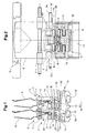
- FIG. 1 shows a conveying means 1 according to the invention a conveyor system according to the invention in a section in Conveying direction F;
- Fig. 2 shows the same arrangement in one Section in a normal plane to the conveying direction F.
- Structure and operation of the funding 1 and the conveyor system are from WO 99/33730, WO 99/33731 and WO 99/33732 known, to which reference is made here.
- Funding 1 and the funding system are as follows therefore only described as far as for understanding the Invention is necessary.
- Fig. 1 two funds 1 are shown, which are in a first guide rail 8 in the conveying direction F can move. They are driven by a drive means 5 driven, here one of individual links 5 ' existing series, which is driven by a mechanical drive Direction of conveyance F is moved.
- the drive means 5 transmits a magnetic force from along the second Rail 9 stationary magnets 17 on Coupling parts 4 of the funding 1.
- Link 5 'of the drive means 5 flow parts 18.
- each perpendicular to the magnet 17 and Coupling part 4 have, with the in between enclosed area in the direction of the coupling part reduced. In this way the magnetic Field lines are bundled and it becomes a high field and therefore achieved a high coupling of the funding.
- the funding 1 consist of a guide part 2, a support part 3 and a coupling part 4.
- Das Guide part 2 slides in the first guide rail 8. It For this purpose, for example, has two on each side Conveying direction F arranged guides 2a, 2b with the first guide rail 8 cooperate.
- the guide part 2 in one Normal plane to the conveying direction F H-shaped, as shown in Fig. 2.
- the guide member 2 is preferred in the conveying direction V-shaped (not shown here).
- the guide part is preferably a support part Axis 24 running perpendicular to the conveying direction F pivotally attached.
- the support part 3 consists of a Clip 6, which is opened with a slide 7 or can be closed. The slide 7 can for example be moved across a backdrop.
- the coupling part 4 is not fixed connected to the guide part 2, but between one first position A, as in the front in the conveying direction F Funding shown, and a second position B, like shown at the rear in the conveying direction F, movable.
- position A the coupling part 4 touches the sliding surface 25 of the drive means 5, which consists of a low-friction material.
- position B it is Coupling part 4 spaced from the sliding surface 25, and the coupling is therefore reduced.
- the coupling part 4 between the Positions A and B movable.
- the possibility of movement is by suitable storage of the coupling part 4th realized within the guide part 2.
- first surface 10 lying in front within the guide part 2 moves against the conveying direction F; at the same time it becomes the drive means second surface 11 pushed away from the sliding surface 25.
- To the coupling part 4 is essentially cuboid designed and in a likewise essentially cuboid recess 13 within the guide part 2 stored so that it is largely immobile on the side, in the conveying direction F and in the direction of the drive means but has little play.
- the recess 13 is both towards the drive means and in Delivery direction F open.
- the coupling part 4 is by means of two laterally arranged pins 15 in an elongated and guide groove 16 oriented obliquely to the conveying direction Guide part movable in the manner described.
- the dimensions of the coupling part 4 are chosen so that the first surface 10 in position A of the Coupling part the foremost area in the conveying direction F. of the funding 1 forms. So that the coupling part 4 moves to the second position B when the conveyor 1 an obstacle, for example a restraint element or one that is already stopped or less Another moving means of conveyance is moving up.
- Fig. 1 is the rear funding in the direction of conveyance F. driven onto the front conveyor so that its Coupling part 4 by acting as a stop 12 Back of the front conveyor into the second Position B has been moved.
- the coupling part 4 faces the drive means 5 opposite side a punctiform or transverse to Delivery direction F aligned extension 14. With this is the coupling part 4 on the inner surface of the Recess 13 in such a way that in the second position B about an axis aligned transversely to the conveying direction F. is movable relative to the guide part 2. By the Extension 14 is achieved that the coupling part 4 not tilted in the recess 13, but in the event of weakening a pressure on the front surface 10 due to the Magnetic attraction again in the first position A returns.
- Fig. 2 is the H-shaped cross section of the guide parts 2 and the drive members 5 'shown.
- Fig. 1 is the standing conveying
- Fig. 3 are both Variants shown.
- the Pressure on the front surface 10 of the coupling part both gravity and magnetic force are overcome and the coupling part in the second position B promoted.
- hanging conveying must, supported by gravity, only magnetic attraction become.
- FIG. 3 and 4 show an example of the application of Invention for the formation of a buffer line both hanging as well as standing conveying within the same conveyor system.
- 3 shows a side view and
- FIG. 4 shows a view in a normal plane Direction of conveyance F.
- a plurality of Funding 1 in a first guide rail 8 and are by a rotating drive means 5 in Direction of conveyance F moves.
- the conveyor system here consists of a lower area in which products are conveyed hanging 21 and an upper area where empty Funding 1 standing, i.e. with pointing upwards Clip 6 are transported.
- a retaining element 19 in the lower Area of the conveyor system holds a first funding 1 ' in the area of its supporting part or from lateral extensions 3a of them.
- the coupling part 4 'of the first funding 1 ' is not touched, so it is in the first Position A with maximum coupling to the drive means 5 is located.
- first funding 1 'in the first position A acts immediately when you release the Retaining element 19 the full conveying force, so that first funding accelerated as soon as you let go and the full transport speed is reached quickly. Move the other buffered funds 1 then until the foremost touches the retaining element 19 strikes.
- FIG. 4 shows the arrangement from FIG. 3 in a normal plane to the direction of conveyance. That on the support part 3 or on the side Extensions 3a of which attack retaining element 19 to release or stop a grant upwards or move below or one perpendicular to the conveying direction extending axis swiveled. That on the coupling part 4 attacking retaining element 19 'is used to stop or release a conveyor linearly sideways or pivoted into or out of the movement path.
- 5 to 7 are further examples of the structure buffer routes and access to individual funding 1 shown from such a buffer section.
- Fig. 5 shows a buffer section in which the funding 1 with one engaging on its coupling part 4 Retaining element 19 'or by running onto the as Stop 12 acting back of the previous one Funding from an original conveying speed V1 to a conveyor speed V2, which is zero here is decelerated.
- This arrangement was already in upper part of Fig. 3 for the case of standing funding shown and in the corresponding figure description explained.
- FIG. 6 shows a further example of a buffer section, in which they originally moved at speed V1 Funding 1 not completely slowed down, but only on brought a speed V2 that is less than V1 become.
- a number of retaining elements 19 are on attached to a rotating wheel 20. The attacks engage as in connection with Fig. 3 lower part described on the support member 3 or extension 3a of the Shortly and give the funding in Free again during the further rotation. As before described, the coupling with the drive means 5 remains in this case fully received, so that from Retaining element 19 held funding according to his Release of full funding is suspended.
- Fig. 7 shows another example of such Buffer zone.
- Individual funds 1 run at speed V1 into a lock drive 22 in which it can be moved at speed V2.
- Ratio of V1 to V2 is the distance between the Subsidies reduced or enlarged.
- the Funding leaves the lock drive 22 continuously and reach the first again Conveying speed V1, however, with changed distance D promoted by the speed V1, V2 and the original delivery distance D0 depends.
Landscapes
- Engineering & Computer Science (AREA)
- Mechanical Engineering (AREA)
- Intermediate Stations On Conveyors (AREA)
- Non-Mechanical Conveyors (AREA)
- Chain Conveyers (AREA)
- Feeding Of Articles By Means Other Than Belts Or Rollers (AREA)
- Attitude Control For Articles On Conveyors (AREA)
- Discharge By Other Means (AREA)
Abstract
Description
- Fig. 1
- Zwei erfindungsgemässe Fördermittel in einem Fördersystem im Längsschnitt in Förderrichtung;
- Fig. 2
- die Anordnung aus Fig. 1 in einem Schnitt in einer Normalebene zur Förderrichtung;
- Fig. 3
- ein erfindungsgemässes Fördersystem in einem Schnitt in Förderrichtung;
- Fig. 4
- das System aus Fig. 3 in einem Schnitt senkrecht zur Förderrichtung;
- Fig. 5-7
- verschiedene Möglichkeiten zum Puffern von Fördermitteln und zum Abruf dieser aus der Pufferstrecke.
Claims (20)
- Schienenführbares Fördermittel (1, 1') zum Fördern von insbesondere flächigen Produkten (21) in eine Förderrichtung (F) mit einem Führungsteil, einem am Führungsteil (2, 2') angeordneten Tragteil (3) zum Halten eines Produktes (21) und einem Ankopplungsteil (4, 4'), das an ein Antriebsmittel (5) ankoppelbar ausgestaltet ist, dadurch gekennzeichnet, dass das Ankopplungsteil (4, 4') zur Variation der Stärke der Ankopplung relativ zum Führungsteil (2, 2') zwischen wenigstens einer ersten Position (A) und einer zweiten Position (B), in der eine gegenüber der ersten Position (A) schwächere Ankopplung vorliegt, beweglich ist und dass das Ankopplungsteil (4, 4') eine erste Fläche (10), die im Anwendungsfall in Förderrichtung (F) vorne liegt, und eine zweite Fläche (11), die im Anwendungsfall dem Antriebsmittel (5) zugewandt ist, aufweist, wobei die zweite Fläche (11) vom Antriebsmittel (5) wegbewegt wird, wenn auf die erste Fläche (10) eine Kraft im wesentlichen entgegen der Förderrichtung (F) ausgeübt wird..
- Fördermittel (1 1') nach Anspruch 1, dadurch gekennzeichnet, dass das Ankopplungsteil (4, 4') schwenkbar mit dem Führungsteil (2, 2') verbunden oder am Führungsteil (2, 2') schwimmend aufgehängt ist.
- Fördermittel (1, 1') nach einem der Ansprüche 1 oder 2, dadurch gekennzeichnet, dass die erste Fläche (10) die in Förderrichtung (F) vordere Fläche des Führungsteils (2, 2') wenigstens in der ersten Position (A) teilweise überragt.
- Fördermittel (1, 1') nach einem der vorangegangenen Ansprüche, dadurch gekennzeichnet, dass die erste Fläche (10) eben ist und vorzugsweise senkrecht zur Förderrichtung orientiert ist.
- Fördermittel (1, 1') nach einem der vorangegangenen Ansprüche, dadurch gekennzeichnet, dass die zweite Fläche (11) eben ist und vorzugsweise parallel zur Förderrichtung orientiert ist.
- Fördermittel (1, 1') nach Anspruch 5, dadurch gekennzeichnet, dass die zweite Fläche (11) bei Krafteinwirkung auf die erste Fläche (10) im wesentlichen parallel zu sich selbst verschoben wird, wobei der Hub vorzugsweise zwischen 0,5 und 5 mm beträgt.
- Fördermittel (1, 1') nach einem der vorangegangenen Ansprüche, dadurch gekennzeichnet, dass das Ankopplungsteil (4, 4') im wesentlichen quaderförmig gestaltet ist und in einer in Förderrichtung (F) und zum Antriebsmittel (5) hin offenen, im wesentlichen quaderförmigen Aussparung (13) im Führungsteil ( 2, 2') angeordnet ist.
- Fördermittel (1, 1') nach einem der vorangegangegen Ansprüche, dadurch gekennzeichnet, dass das Ankopplungsteil (4, 4') wenigstens im zweiten Zustand (B) um eine quer zur Förderrichtung (F) ausgerichtete Achse relativ zum Führungsteil (2, 2') beweglich ist, vorzugsweise indem es an seiner dem Antriebsmittel (5) abgewandten Seite einen Fortsatz (14) aufweist, der im zweiten Zustand (B) an einer Innenfläche der Aussparung (13) anliegt und eine Schwenkbewegung ermöglicht.
- Fördermittel (1, 1') nach einem der vorangegangegen Ansprüche, dadurch gekennzeichnet, dass das Ankopplungsteil (4, 4') zur Aufhängung innerhalb des Führungsteils (2, 2') an seinen parallel zur Förderrichtung (F) ausgerichteten Seiten Stifte (15) aufweist, die in länglichen, schräg zur Förderrichtung (F) ausgerichteten Führungsnuten (16) des Führungsteils (2, 2') zu gleiten imstande sind.
- Fördermittel (1, 1') nach einem der einem der vorangegangegen Ansprüche, dadurch gekennzeichnet, dass es an seiner in Förderrichtung (F) gesehen hinteren Seite einen Anschlag (12) aufweist, durch den das Ankopplungsteil (4, 4') eines weiteren Fördermittels (1, 1'), das an den Anschlag (12) anstösst, von der ersten Position (A) in die zweite Position (B) bewegt wird.
- Fördermittel (1, 1') nach einem der vorangegangenen Ansprüche, dadurch gekennzeichnet, dass das Ankopplungsteil (4, 4') wenigstens teilweise aus einem ferromagnetischen Material besteht.
- Fördermittel (1, 1')nach einem der vorangegangenen Ansprüche, dadurch gekennzeichnet, dass das Führungsteil (2, 2') in Förderrichtung (F) V-förmig verläuft, wobei es vorzugsweise eine Dreipunktabstützung ausbildet.
- Fördermittel (1, 1') nach einem der vorangegangenen Ansprüche, dadurch gekennzeichnet, dass das Führungsteil (2, 2') zwei seitlich in Förderrichtung (F) angeordnete Führungen (2a, 2b) aufweist, in die im Anwendungsfall Führungsschienen (8) eines Fördersystems eingreifen, wobei das Führungsteil (2, 2') vorzugsweise in einer Normalebene zur Förderrichtung H-förmig ausgestaltet ist.
- Fördersystem mit einer ersten Führungssschiene (8) zur Aufnahme einer Mehrzahl von Fördermitteln (1, 1'), die in der Führungsschiene (8) individuell beweglich sind, und einer zweiten Führungsschiene (9) mit einem daran geführten Antriebsmittel (5), das ein derartiges Koppeln an ein Ankopplungsteil (4, 4') des Fördermittels (1, 1') zulässt, dass das Fördermittel (1, 1') im angekoppelten Zustand vom Antriebsmittel (5) beweglich ist, dadurch gekennzeichnet, dass das Ankopplungsteil (4, 4') so gestaltet ist, dass die Stärke der Ankopplung an das Antriebsmittel (5) variabel ist.
- Fördersystem nach Anspruch 14, dadurch gekennzeichnet, dass die Ankopplung eines Fördermittels (1, 1') an das Antriebsmittel (5) magnetisch erfolgt, indem eine Mehrzahl von Magneten (17) entlang der zweiten Führungsschiene (9) angeordnet sind und die Antriebsmittel (5) die magnetische Kraft vorzugsweise mittels ferromagnetischer Flussteile (18) auf ein Ankopplungsteil (4, 4') eines Fördermittels (1, 1') übertragen.
- Fördersystem nach Anspruch 15, dadurch gekennzeichnet, dass jeweils zwei Flussteile (18) einander gegenüberliegen und im Bereich des Magneten (17) und der ersten Führungsschiene (8) im wesentlichen senkrecht zum Magneten (17) bzw. zum Fördermittel (1, 1') ausgerichtet sind, wobei der Abstand der Flussteile (18) im Bereich der ersten Führungsschiene (8) gegenüber dem Abstand im Bereich des Magneten (17) verringert ist.
- Fördersystem nach einem der Ansprüche 14 bis 16, dadurch gekennzeichnet, dass im Bereich der ersten Führungsschiene (8) wenigstens ein schaltbares Rückhalteelement (19, 19') angeordnet ist, das ein Fördermittel (1, 1') zu stoppen imstande ist.
- Fördersystem nach Anspruch 17, dadurch gekennzeichnet, dass das Rückhalteelement (19, 19') am Ankopplungsteil (4, 4') oder am Führungsteil (2, 2') oder am Tragteil (3) angreift.
- Fördersystem nach einem der Ansprüche 14 bis 18 mit einem Fördermittel nach einem der Ansprüche 1 bis 13.
- Verwendung eines Fördermittels nach einem der Ansprüche 1 bis 13 in einem Fördersystem nach einem der Ansprüche 14 bis 18.
Applications Claiming Priority (2)
| Application Number | Priority Date | Filing Date | Title |
|---|---|---|---|
| CH24632000 | 2000-12-18 | ||
| CH24632000 | 2000-12-18 |
Publications (2)
| Publication Number | Publication Date |
|---|---|
| EP1215142A1 true EP1215142A1 (de) | 2002-06-19 |
| EP1215142B1 EP1215142B1 (de) | 2004-08-11 |
Family
ID=4569424
Family Applications (1)
| Application Number | Title | Priority Date | Filing Date |
|---|---|---|---|
| EP01128207A Expired - Lifetime EP1215142B1 (de) | 2000-12-18 | 2001-11-28 | Schienenführbares Fördermittel und Fördersystem |
Country Status (4)
| Country | Link |
|---|---|
| US (1) | US6742648B2 (de) |
| EP (1) | EP1215142B1 (de) |
| AT (1) | ATE273216T1 (de) |
| DE (1) | DE50103205D1 (de) |
Cited By (1)
| Publication number | Priority date | Publication date | Assignee | Title |
|---|---|---|---|---|
| WO2008098782A1 (de) * | 2007-02-16 | 2008-08-21 | Rsl Logistik Gmbh & Co. Kg | Separator und damit ausgestattete hängefördereinrichtung |
Families Citing this family (8)
| Publication number | Priority date | Publication date | Assignee | Title |
|---|---|---|---|---|
| DE102008037188A1 (de) * | 2008-08-11 | 2010-02-18 | Krones Ag | Vorrichtung und Verfahren zum Bilden von Stückgüterzusammenstellungen |
| DE102011080441B4 (de) * | 2011-08-04 | 2023-01-12 | Krones Aktiengesellschaft | Speichervorrichtung für eine Abfüllanlage und Getränkeabfüllanlage mit einer solchen Speichervorrichtung |
| CH709392A1 (de) * | 2014-03-20 | 2015-09-30 | Ferag Ag | Eintaktvorrichtung für Gravitationsförderer. |
| CH710650A1 (de) * | 2015-01-26 | 2016-07-29 | Ferag Ag | Transportvorrichtung, insbesondere in Form eines Hängeförderers. |
| CH712895A1 (de) | 2016-09-09 | 2018-03-15 | Ferag Ag | Verfahren zum Öffnen einer an einem Laufwagen hängenden Transporttasche sowie Taschenöffnungsvorrichtung zur Durchführung des Verfahrens. |
| DE202017100206U1 (de) | 2017-01-16 | 2018-04-17 | Tgw Mechanics Gmbh | Fördergutbehälter mit Auswerfvorrichtung und zugehörige Hängefördervorrichtung |
| DE102017122754A1 (de) * | 2017-09-29 | 2019-04-04 | MAX-PLANCK-Gesellschaft zur Förderung der Wissenschaften e.V. | Vorrichtung sowie Vakuumkammer |
| CN115303775B (zh) * | 2022-08-12 | 2025-01-10 | 浙江衣拿智能科技股份有限公司 | 一种分拨装置 |
Citations (8)
| Publication number | Priority date | Publication date | Assignee | Title |
|---|---|---|---|---|
| US3807314A (en) * | 1973-03-30 | 1974-04-30 | Us Army | Magnetic trolley conveyor system |
| US4114539A (en) * | 1975-12-11 | 1978-09-19 | Murata Kikai Kabushiki Kaisha | Means for transferring, collecting and distributing trolleys in conveyer system |
| US4718349A (en) * | 1985-05-29 | 1988-01-12 | Wahren Per E | Conveyor line for heavy goods conveying |
| US5222587A (en) * | 1991-07-17 | 1993-06-29 | Machines Assemblage Automatique | Device for moving parts from one station to another along a line for processing them |
| DE19538350A1 (de) * | 1995-10-14 | 1997-04-17 | Schlafhorst & Co W | Hängefördersystem für Textilspulen |
| WO1999033731A1 (de) | 1997-12-23 | 1999-07-08 | Ferag Ag | Fördersystem |
| WO1999033732A1 (de) | 1997-12-23 | 1999-07-08 | Ferag Ag | Fördereinrichtung |
| WO1999033730A1 (de) | 1997-12-23 | 1999-07-08 | Ferag Ag | Schienenführbares fördermittel und führungsschiene zum führen des fördermittels |
Family Cites Families (4)
| Publication number | Priority date | Publication date | Assignee | Title |
|---|---|---|---|---|
| NL112491C (de) | 1959-12-23 | |||
| US3782529A (en) * | 1972-07-12 | 1974-01-01 | Bucciconi Eng Co | Magnetic rail conveyor |
| US4051946A (en) * | 1976-03-12 | 1977-10-04 | Bucciconi Engineering Co., Inc. | Magnetic conveyor |
| AU738623B2 (en) * | 1997-12-23 | 2001-09-20 | Ferag Ag | Apparatus for receiving and/or discharging sheet-like products |
-
2001
- 2001-11-28 AT AT01128207T patent/ATE273216T1/de not_active IP Right Cessation
- 2001-11-28 DE DE50103205T patent/DE50103205D1/de not_active Expired - Lifetime
- 2001-11-28 EP EP01128207A patent/EP1215142B1/de not_active Expired - Lifetime
- 2001-12-17 US US10/024,302 patent/US6742648B2/en not_active Expired - Fee Related
Patent Citations (8)
| Publication number | Priority date | Publication date | Assignee | Title |
|---|---|---|---|---|
| US3807314A (en) * | 1973-03-30 | 1974-04-30 | Us Army | Magnetic trolley conveyor system |
| US4114539A (en) * | 1975-12-11 | 1978-09-19 | Murata Kikai Kabushiki Kaisha | Means for transferring, collecting and distributing trolleys in conveyer system |
| US4718349A (en) * | 1985-05-29 | 1988-01-12 | Wahren Per E | Conveyor line for heavy goods conveying |
| US5222587A (en) * | 1991-07-17 | 1993-06-29 | Machines Assemblage Automatique | Device for moving parts from one station to another along a line for processing them |
| DE19538350A1 (de) * | 1995-10-14 | 1997-04-17 | Schlafhorst & Co W | Hängefördersystem für Textilspulen |
| WO1999033731A1 (de) | 1997-12-23 | 1999-07-08 | Ferag Ag | Fördersystem |
| WO1999033732A1 (de) | 1997-12-23 | 1999-07-08 | Ferag Ag | Fördereinrichtung |
| WO1999033730A1 (de) | 1997-12-23 | 1999-07-08 | Ferag Ag | Schienenführbares fördermittel und führungsschiene zum führen des fördermittels |
Cited By (1)
| Publication number | Priority date | Publication date | Assignee | Title |
|---|---|---|---|---|
| WO2008098782A1 (de) * | 2007-02-16 | 2008-08-21 | Rsl Logistik Gmbh & Co. Kg | Separator und damit ausgestattete hängefördereinrichtung |
Also Published As
| Publication number | Publication date |
|---|---|
| US6742648B2 (en) | 2004-06-01 |
| EP1215142B1 (de) | 2004-08-11 |
| ATE273216T1 (de) | 2004-08-15 |
| DE50103205D1 (de) | 2004-09-16 |
| US20020073874A1 (en) | 2002-06-20 |
Similar Documents
| Publication | Publication Date | Title |
|---|---|---|
| DE1786486C3 (de) | Vorrichtung zum Sammeln und Be fordern einer Gruppe von Verpackungs einheiten, beispielsweise Flaschen, Dosen u dgl in eine Station zum gruppen weisen Einhüllen solcher Verpackungs einheiten in Verpackungsmaterial Ausscheidung aus 1561939 | |
| EP0286080B1 (de) | Vorrichtung zum Steuern des Transportweges von Gegenständen | |
| DE68909702T2 (de) | Sortiereinheit für Bandfördersysteme. | |
| DE2125991A1 (de) | Verfahren und Vorrichtung zum Transport gestapelter flacher Gegenstände in Aufeinanderfolge zu einem Auffangen | |
| EP0883565B1 (de) | Transport- und sammelsystem | |
| DE69611740T2 (de) | Vorrichtung zum Sortieren von Produkten | |
| EP0942886A1 (de) | Sortiervorrichtung für stückgut und verfahren zu deren betrieb | |
| EP1123884A1 (de) | Vorrichtung zum Ablenken von Gegenständen, insbesondere Behältern, von einer Bewegungsbahn | |
| EP2428471B1 (de) | Fördersystem | |
| EP4074629A1 (de) | Hängeförderer mit einer entladestation | |
| DE102011100825B4 (de) | Spindelförderer und Anlage zum Behandeln von Werkstücken mit einem solchen | |
| EP1215142B1 (de) | Schienenführbares Fördermittel und Fördersystem | |
| EP0727370B1 (de) | Förderanlage | |
| EP1042206B1 (de) | Vorrichtung zum aufnehmen und/oder abgeben flächiger erzeugnisse | |
| DE102017008044A1 (de) | Ausleitvorrichtung mit Coanda-Stabilisierungseinrichtung | |
| EP1042204B1 (de) | Fördereinrichtung | |
| DE4116991A1 (de) | Vorrichtung zum stapelweisen ablegen und ausrichten von einzeln zugefuehrten blaettern | |
| EP0530756B1 (de) | Vorrichtung zum Verbreitern eines einspurigen Förderstromes aufrechtstehender Behälter | |
| EP1042202A1 (de) | Schienenführbares fördermittel und führungsschiene zum führen des fördermittels | |
| EP0657259A1 (de) | Tonstrang-Schneidevorrichtung | |
| DE102006023987B4 (de) | Anordnung zum Einschleusen von Fördergütern in mittels einer Fördereinrichtung bewegbare Fördergutbehälter | |
| DE3931534C2 (de) | ||
| DE2100253C3 (de) | Haltestation für eine Schleppkettenkreisförderanlage | |
| DE2653895A1 (de) | Foerdervorrichtung zum waehlen von transportbahnen | |
| DE3318047A1 (de) | Auswerfer |
Legal Events
| Date | Code | Title | Description |
|---|---|---|---|
| PUAI | Public reference made under article 153(3) epc to a published international application that has entered the european phase |
Free format text: ORIGINAL CODE: 0009012 |
|
| AK | Designated contracting states |
Kind code of ref document: A1 Designated state(s): AT BE CH CY DE DK ES FI FR GB GR IE IT LI LU MC NL PT SE TR |
|
| AX | Request for extension of the european patent |
Free format text: AL;LT;LV;MK;RO;SI |
|
| 17P | Request for examination filed |
Effective date: 20020705 |
|
| AKX | Designation fees paid |
Designated state(s): AT BE CH CY DE DK ES FI FR GB GR IE IT LI LU MC NL PT SE TR |
|
| 17Q | First examination report despatched |
Effective date: 20030812 |
|
| GRAP | Despatch of communication of intention to grant a patent |
Free format text: ORIGINAL CODE: EPIDOSNIGR1 |
|
| GRAS | Grant fee paid |
Free format text: ORIGINAL CODE: EPIDOSNIGR3 |
|
| GRAA | (expected) grant |
Free format text: ORIGINAL CODE: 0009210 |
|
| AK | Designated contracting states |
Kind code of ref document: B1 Designated state(s): AT BE CH CY DE DK ES FI FR GB GR IE IT LI LU MC NL PT SE TR |
|
| PG25 | Lapsed in a contracting state [announced via postgrant information from national office to epo] |
Ref country code: FI Free format text: LAPSE BECAUSE OF FAILURE TO SUBMIT A TRANSLATION OF THE DESCRIPTION OR TO PAY THE FEE WITHIN THE PRESCRIBED TIME-LIMIT Effective date: 20040811 Ref country code: FR Free format text: LAPSE BECAUSE OF FAILURE TO SUBMIT A TRANSLATION OF THE DESCRIPTION OR TO PAY THE FEE WITHIN THE PRESCRIBED TIME-LIMIT Effective date: 20040811 Ref country code: IE Free format text: LAPSE BECAUSE OF FAILURE TO SUBMIT A TRANSLATION OF THE DESCRIPTION OR TO PAY THE FEE WITHIN THE PRESCRIBED TIME-LIMIT Effective date: 20040811 Ref country code: CY Free format text: LAPSE BECAUSE OF FAILURE TO SUBMIT A TRANSLATION OF THE DESCRIPTION OR TO PAY THE FEE WITHIN THE PRESCRIBED TIME-LIMIT Effective date: 20040811 Ref country code: NL Free format text: LAPSE BECAUSE OF FAILURE TO SUBMIT A TRANSLATION OF THE DESCRIPTION OR TO PAY THE FEE WITHIN THE PRESCRIBED TIME-LIMIT Effective date: 20040811 Ref country code: GB Free format text: LAPSE BECAUSE OF FAILURE TO SUBMIT A TRANSLATION OF THE DESCRIPTION OR TO PAY THE FEE WITHIN THE PRESCRIBED TIME-LIMIT Effective date: 20040811 Ref country code: TR Free format text: LAPSE BECAUSE OF FAILURE TO SUBMIT A TRANSLATION OF THE DESCRIPTION OR TO PAY THE FEE WITHIN THE PRESCRIBED TIME-LIMIT Effective date: 20040811 Ref country code: IT Free format text: LAPSE BECAUSE OF FAILURE TO SUBMIT A TRANSLATION OF THE DESCRIPTION OR TO PAY THE FEE WITHIN THE PRESCRIBED TIME-LIMIT;WARNING: LAPSES OF ITALIAN PATENTS WITH EFFECTIVE DATE BEFORE 2007 MAY HAVE OCCURRED AT ANY TIME BEFORE 2007. THE CORRECT EFFECTIVE DATE MAY BE DIFFERENT FROM THE ONE RECORDED. Effective date: 20040811 |
|
| REG | Reference to a national code |
Ref country code: GB Ref legal event code: FG4D Free format text: NOT ENGLISH |
|
| REG | Reference to a national code |
Ref country code: CH Ref legal event code: EP |
|
| REG | Reference to a national code |
Ref country code: CH Ref legal event code: NV Representative=s name: PATENTANWAELTE SCHAAD, BALASS, MENZL & PARTNER AG |
|
| REG | Reference to a national code |
Ref country code: IE Ref legal event code: FG4D Free format text: GERMAN |
|
| REF | Corresponds to: |
Ref document number: 50103205 Country of ref document: DE Date of ref document: 20040916 Kind code of ref document: P |
|
| PG25 | Lapsed in a contracting state [announced via postgrant information from national office to epo] |
Ref country code: SE Free format text: LAPSE BECAUSE OF FAILURE TO SUBMIT A TRANSLATION OF THE DESCRIPTION OR TO PAY THE FEE WITHIN THE PRESCRIBED TIME-LIMIT Effective date: 20041111 Ref country code: DK Free format text: LAPSE BECAUSE OF FAILURE TO SUBMIT A TRANSLATION OF THE DESCRIPTION OR TO PAY THE FEE WITHIN THE PRESCRIBED TIME-LIMIT Effective date: 20041111 Ref country code: GR Free format text: LAPSE BECAUSE OF FAILURE TO SUBMIT A TRANSLATION OF THE DESCRIPTION OR TO PAY THE FEE WITHIN THE PRESCRIBED TIME-LIMIT Effective date: 20041111 |
|
| PG25 | Lapsed in a contracting state [announced via postgrant information from national office to epo] |
Ref country code: ES Free format text: LAPSE BECAUSE OF FAILURE TO SUBMIT A TRANSLATION OF THE DESCRIPTION OR TO PAY THE FEE WITHIN THE PRESCRIBED TIME-LIMIT Effective date: 20041122 |
|
| PG25 | Lapsed in a contracting state [announced via postgrant information from national office to epo] |
Ref country code: AT Free format text: LAPSE BECAUSE OF NON-PAYMENT OF DUE FEES Effective date: 20041128 Ref country code: LU Free format text: LAPSE BECAUSE OF NON-PAYMENT OF DUE FEES Effective date: 20041128 |
|
| PG25 | Lapsed in a contracting state [announced via postgrant information from national office to epo] |
Ref country code: BE Free format text: LAPSE BECAUSE OF NON-PAYMENT OF DUE FEES Effective date: 20041130 Ref country code: MC Free format text: LAPSE BECAUSE OF NON-PAYMENT OF DUE FEES Effective date: 20041130 |
|
| NLV1 | Nl: lapsed or annulled due to failure to fulfill the requirements of art. 29p and 29m of the patents act | ||
| GBV | Gb: ep patent (uk) treated as always having been void in accordance with gb section 77(7)/1977 [no translation filed] |
Effective date: 20040811 |
|
| REG | Reference to a national code |
Ref country code: IE Ref legal event code: FD4D |
|
| BERE | Be: lapsed |
Owner name: FERAG AG Effective date: 20041130 |
|
| PLBE | No opposition filed within time limit |
Free format text: ORIGINAL CODE: 0009261 |
|
| STAA | Information on the status of an ep patent application or granted ep patent |
Free format text: STATUS: NO OPPOSITION FILED WITHIN TIME LIMIT |
|
| 26N | No opposition filed |
Effective date: 20050512 |
|
| EN | Fr: translation not filed | ||
| EN | Fr: translation not filed | ||
| BERE | Be: lapsed |
Owner name: *FERAG A.G. Effective date: 20041130 |
|
| PG25 | Lapsed in a contracting state [announced via postgrant information from national office to epo] |
Ref country code: PT Free format text: LAPSE BECAUSE OF NON-PAYMENT OF DUE FEES Effective date: 20050111 |
|
| PGFP | Annual fee paid to national office [announced via postgrant information from national office to epo] |
Ref country code: DE Payment date: 20141119 Year of fee payment: 14 |
|
| PGFP | Annual fee paid to national office [announced via postgrant information from national office to epo] |
Ref country code: CH Payment date: 20150128 Year of fee payment: 14 |
|
| REG | Reference to a national code |
Ref country code: DE Ref legal event code: R119 Ref document number: 50103205 Country of ref document: DE |
|
| REG | Reference to a national code |
Ref country code: CH Ref legal event code: PL |
|
| PG25 | Lapsed in a contracting state [announced via postgrant information from national office to epo] |
Ref country code: LI Free format text: LAPSE BECAUSE OF NON-PAYMENT OF DUE FEES Effective date: 20151130 Ref country code: CH Free format text: LAPSE BECAUSE OF NON-PAYMENT OF DUE FEES Effective date: 20151130 |
|
| PG25 | Lapsed in a contracting state [announced via postgrant information from national office to epo] |
Ref country code: DE Free format text: LAPSE BECAUSE OF NON-PAYMENT OF DUE FEES Effective date: 20160601 |