EP1215105A2 - Traction apparatus of trailer - Google Patents
Traction apparatus of trailer Download PDFInfo
- Publication number
- EP1215105A2 EP1215105A2 EP01129423A EP01129423A EP1215105A2 EP 1215105 A2 EP1215105 A2 EP 1215105A2 EP 01129423 A EP01129423 A EP 01129423A EP 01129423 A EP01129423 A EP 01129423A EP 1215105 A2 EP1215105 A2 EP 1215105A2
- Authority
- EP
- European Patent Office
- Prior art keywords
- rotary body
- trailer
- full trailer
- balanced full
- vertical axis
- Prior art date
- Legal status (The legal status is an assumption and is not a legal conclusion. Google has not performed a legal analysis and makes no representation as to the accuracy of the status listed.)
- Granted
Links
Images


Classifications
-
- B—PERFORMING OPERATIONS; TRANSPORTING
- B62—LAND VEHICLES FOR TRAVELLING OTHERWISE THAN ON RAILS
- B62D—MOTOR VEHICLES; TRAILERS
- B62D13/00—Steering specially adapted for trailers
- B62D13/06—Steering specially adapted for trailers for backing a normally drawn trailer
Definitions
- the present invention relates to a trailer traveling in a state of being connected to a tractor, and more particularly to a traction apparatus of a trailer in which it is easy to steer to left and right turn at a time of backward traveling in a full trailer connected by a tow bar.
- a trailer in particular, a full trailer (hereinafter, refer to "a trailer") 102 connected to a tractor 101 via a tow bar 110 is provided with a balanced full trailer 105 in which a front end portion of a truck frame 103 of the trailer 102 is rotatably supported via a rotor 104 around a vertical axis, as shown in Fig. 11, the balanced full trailer 105 and the truck frame 103 have front wheels 106 and rear wheels 108, the tow bar 110 is connected to two points at left and right positions a and b in a front cross member 113 of the balanced full trailer 105 so as to form a triangular shape as shown in Fig.
- a front end side of the tow bar 110 is rotatably connected to a connecting device 115 provided in a rear center portion of the trailer 101 by a lunette eye 114. Further, a backward travel of the trailer 102 is executed by rotating and steering the balanced full trailer 105 via the tow bar 110 while controlling an orientation of the tractor 101 according to a steering operation of the tractor 101.
- the tractor 101 moves backward while operating the direction of the tractor 101 so that the force is applied to any one of the connecting points a and b of the tow rod 102 so as to rotate and steer the balanced full trailer 105. Since it is necessary to execute the steering operation of the tractor 101 so that a jackknife phenomenon bending around a connection portion 115 between the tractor 101 and the tow bar 110 is not generated and rotating direction of the balanced full trailer 105 is suitably transmitted to the tow bar 110, at a time of backward moving, it is significantly hard to steer a long vehicle body such as the full trailer so as to backward move to left and right in a rounded manner, so that not only a skill is required but also there is a problem that a wide space is required for setting in an indicated place.
- the present invention has been made by taking the problem mentioned above into consideration, and an object of the present invention is to provide a traction apparatus of a trailer in which a tractor can be steered only as a power for moving backward by independently steering a balanced full trailer itself with respect to a chassis frame without steering the balanced full trailer to a backward direction according to a steering operation of the tractor.
- a traction apparatus of a trailer provided with a balanced full trailer in a front portion of a truck frame so as to freely rotate around a vertical axis via a rotor and connecting a front end portion of the balanced full trailer to the tractor by a tow bar, comprising:
- a traction apparatus of a trailer provided with a balanced full trailer in a front portion of a truck frame so as to freely rotate around a vertical axis via a rotor and connecting a front end portion of the balanced full trailer to the tractor by a tow bar, comprising:
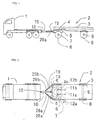
- Fig. 1 is a schematic side view showing a state that a tractor is connected to a trailer
- Fig. 2 is a plan view thereof
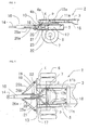
- Fig. 3 is an enlarged side view of a main portion showing a state that a front portion of the trailer and a tow bar are placed
- Fig. 4 is a plan view of the main portion
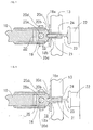
- Fig. 5 is an exploded perspective view of a connection assembly of the tow bar.
- Reference numeral 1 denotes a tractor
- reference numeral 2 denotes a trailer
- the trailer 2 is provided with a balanced full trailer 5 capable of rotating around a vertical axis via a rotor 4 in a front portion of a truck frame 3, an axle 7 of front wheels 6 is suspended to the balanced full trailer 5, and an axle 9 of rear wheels 8 is suspended to the truck frame 3.
- the trailer 2 connects a front end of the balanced full trailer 5 to a rear end portion of the tractor 1 by a tow bar 10.
- a pair of hydraulic cylinders 11a and 11b for rotating in a clockwise direction and in a counterclockwise direction are provided in the rotor 4, the structure is made such as to rotate steer the rotor 4 in a clockwise direction or in a counterclockwise direction by expanding and contracting expansion and contraction rods 12a and 12b of a pair of hydraulic cylinders 11a and 11b, the tow bar 10 formed in a straight long shape via a connection assembly mentioned below is placed in a center portion of a front end cross member 13 of the balanced full trailer 5 so as to be fixedly held and freely rotate, and an eyelet 14 at a front end of the tow bar 10 is connected and placed to a connecting device 15, for example, spindle hook or the like, provided in a rear center portion of the tractor 1 in a such a manner as to freely rotate and freely engage and disengage.
- a connecting device 15 for example, spindle hook or the like
- the rotor 4 is structured such that an outer ring 4a corresponding to a fixed side is adhered to the balanced full trailer 5 and an inner ring 4b corresponding to a moveable side is adhered to the truck frame 3, and is placed so as to rotate and steer the inner ring 4b in a clockwise direction and a counterclockwise direction by a pair of hydraulic cylinders 11a and 11b for rotating in a clockwise direction and in a counterclockwise direction.
- a pair of hydraulic cylinders 11a and 11b are pivoted and placed to a cleat 16 crossing over the truck frame 3, the respective expansion and contraction rods 12a and 12b of the hydraulic cylinders 11a and 11b are pivoted and placed at left and right positions P 1 and P 2 of a cleat 17 crossing over the inner ring 4b of the rotor 4 so as to pass through a substantially center of the inner ring 4b and be parallel to the axle 7, and the balanced full trailer 5 is rotated according to the expanding and contracting operation of the expansion and contraction rods 12a and 12b.
- the hydraulic cylinders 11a and 11b can be expanded and contracted from a driver's seat of the tractor 1 by a remote control apparatus.
- a pair of hydraulic cylinders 11a and 11b are placed in the truck frame 3, however the hydraulic cylinders 11a and 11b may be placed in the balanced full trailer 5, and even in this case, the expansion and contraction rods 12a and 12b can be provided in the inner ring 4b corresponding to the moveable side.
- connection assembly of the two bar 10 is constituted by a bracket 18 adhered and placed to a front center portion of the front end cross member 13 in the balanced full trailer 5, a rotary body 20 received in the bracket 18 and provided so as to freely rotate around a vertical axis by a pin 19, and a stopper 21 engaging with the rotary body 20 so as to maintain the rotary body in a non-rotatable state.
- the bracket 18 is, as shown in Figs. 5 and 6, such that a through hole 18b is pierced in a center portion of a mounting plate portion 18a, a through hole 13a is pierced in the cross member 13, and the through hole 18b of the mounting plate portion 18a and the through hole 13a of the cross member 13 are overlapped and communicated with each other so as to be adhered and placed.
- a pin hole 18c is pierced so as to vertically pass through the bracket 18, a pin hole 20a overlapping and communicating with the pin hole 18c is pierced in the rotary body 20 so as to pass through from an upper surface to a lower surface, and the rotary body 20 is placed so as to freely rotate around a vertical axis by inserting and attaching a pin 19 thereto.
- the rotary body 20 is structured such that a circular surface 20b concentric with the pin hole 20a is provided in one side surface facing to the mounting plate portion 18a of the bracket 18, a wedge-shaped recess portion 20c is pierced in a center portion of the circular surface 20b and connecting shafts 20d are integrally formed on left and right side surfaces in a protruding manner so as to be orthogonal to the wedge-shaped recess portion 20c, the rotary body 20 is placed so that the circular surface 20b thereof faces to the mounting plate portion 18a of the bracket 18, and the tow bar 10 is mounted to the connected shafts 20d.
- reference numeral 19a denotes a cap of the pin 19.
- the stopper 21 having a front end formed in a wedge shape is provided in a back surface of the cross member 13, and the stopper 21 is connected to an operating shaft 23 of an accumulator 22 in a freely forward and backward moving manner and is placed so as to freely engage a front end of the stopper 21 with the wedge-shaped recess portion 20c of the rotary body 20 via the through holes 13a and 18b pierced in the cross member 13 and the mounting plate portion 18a of the rotary body 20. Further, at a time of forward traveling, the stopper 21 engages with the wedge-shaped recess portion 20c of the rotary body 20 so as to make a normal travel possible. Further, at a time of backward moving, the stopper 21 is away from the wedge-shaped recess portion 20c of the rotary body 20, whereby the rotary body 20 can freely rotate around a vertical axis within a fixed range by the circular surface 20.
- a pair of upper and lower stopper guide frames 24 constituting a U-shaped frame are connected and placed to the mounting plate portion 18a of the rotary body 20 via the through hole 18b from the back surface of the front end cross member 13 so as to conduct and guide the front end of the stopper 21 to the wedge-shaped recess portion 20c of the rotary body 20 according to a forward and backward guiding operation of the stopper 21.
- a pair of hydraulic cylinders 25a and 25b are provided at symmetrical positions of the tow bar 10. Base end portions of a pair of hydraulic cylinders 25a and 25b are swingably placed at left and right positions of the front end cross member 13 in the balanced full trailer 5, and front ends of expansion and contraction rods 26a and 26b are placed at symmetrical positions of left and right side surfaces of the tow bar 10. Further, a pair of hydraulic cylinders 25a and 25b serve as a damper for filling up a deficiency in a strength of the connection assembly.
- the traction apparatus of the trailer according to the present invention is fixed and held in a state that the rotation of the rotary body 20 can not executed, by operating the accumulator 22 so as to insert and engage the front end of the stopper 21 with respect to the wedge-shaped recess portion 20c of the rotary body 20, as shown in Figs. 6 and 7 during the forward traveling, and the tow bar 10 is fixed and maintained in an orthogonal state with respect to the front end cross member 13 of the balanced full trailer 5.
- the tow bar 10 according to the present invention can travel with guiding the balanced full trailer 5 so as to rotate in a rounded direction together with the forward rounded traveling of the tractor 1, in the same manner as the conventional tow bar.
- the rotary body 20 can freely rotate around the pin 19 by operating the accumulator 22 so as to move the front end of the stopper 21 away from the wedge-shaped recess portion 20c of the rotary body 20, and the tow bar 10 becomes in a rotatable state around the vertical axis by the rotary body 20.
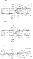
- Fig. 10 shows another embodiment according to the present invention.
- the connection assembly of the tow bar 10 is the same as the assembly shown in Fig. 5, and is constituted by the bracket 18 adhered and placed to the front center portion of the front end cross member 13 in the balanced full trailer 5, the rotary 20 received in the bracket 18 and provided so as to freely rotate around the vertical axis by the pin 19, and the stopper 21 engaging with the rotary body 20 so as to maintain the rotary body in a non-rotatable state.
- the stopper 21 engages with the wedge-shaped recess portion 20c of the rotary body 20, whereby the rotary body is in a state of incapable of rotating, and at a time of backward travelling, the stopper 21 is moved away from the wedge-shaped recess portion of the rotary body 20, whereby the rotary body 20 is in a state of capable of rotating around the vertical axis.
- a pair of left and right hydraulic cylinders 27a and 27b are symmetrically placed with holding the two bar 10 therebetween.
- a pair of cylinders 27a and 27b are pivotally placed at left and right points P 3 and P 4 of the front end cross member 13 in the balanced full trailer 5, respectively, and the respective expansion and contraction rods 28a and 28b are pivotally placed at symmetrical positions on the left and right side surfaces of the tow bar 10.
- At least one hydraulic cylinder 29 serving as a damper is provided in the inner ring 4b corresponding to the moveable side of the rotor 4.
- the balanced full trailer 5 rotates around the vertical axis via the rotary body in the connection portion of the tow bar 10 so as to make it possible to steer the front wheels 6 in a desired turning direction. Then, the trailer 1 serves only as a power source for moving backward.
- the backward travel of the trailer can significantly easily and simply define the backward direction of the balanced full trailer by directly steering the balanced full trailer, and the trailer serves only as the power of backward traveling, there is obtained an effect that the backward steering of the trailer can be made significantly easy.
Abstract
Description
- The present invention relates to a trailer traveling in a state of being connected to a tractor, and more particularly to a traction apparatus of a trailer in which it is easy to steer to left and right turn at a time of backward traveling in a full trailer connected by a tow bar.
- In conventional, a trailer, in particular, a full trailer (hereinafter, refer to "a trailer") 102 connected to a
tractor 101 via atow bar 110 is provided with a balancedfull trailer 105 in which a front end portion of atruck frame 103 of thetrailer 102 is rotatably supported via arotor 104 around a vertical axis, as shown in Fig. 11, the balancedfull trailer 105 and thetruck frame 103 havefront wheels 106 andrear wheels 108, thetow bar 110 is connected to two points at left and right positions a and b in afront cross member 113 of the balancedfull trailer 105 so as to form a triangular shape as shown in Fig. 12, and a front end side of thetow bar 110 is rotatably connected to a connectingdevice 115 provided in a rear center portion of thetrailer 101 by a lunette eye 114. Further, a backward travel of thetrailer 102 is executed by rotating and steering the balancedfull trailer 105 via thetow bar 110 while controlling an orientation of thetractor 101 according to a steering operation of thetractor 101. - However, conventionally, in this kind of full trailer, in the case of backward traveling in a state of being connected to the tractor, no particular difficulty exists in a linear backward movement, however, in a rounded backward moving operation to right and left, not only a significantly hard steering operation is compelled, but also a wide range of moving area is required. That is, a backward moving direction of the
trailer 102 has been achieved by rotating therotor 104 due to a force applied in a deflection manner to any one of the left and right points of thetow bar 110, that is, the connecting points a and b of the balancedfull trailer 105, in correspondence to the backward moving direction of thetractor 101. Accordingly, it is necessary that thetractor 101 moves backward while operating the direction of thetractor 101 so that the force is applied to any one of the connecting points a and b of thetow rod 102 so as to rotate and steer the balancedfull trailer 105. Since it is necessary to execute the steering operation of thetractor 101 so that a jackknife phenomenon bending around aconnection portion 115 between thetractor 101 and thetow bar 110 is not generated and rotating direction of the balancedfull trailer 105 is suitably transmitted to thetow bar 110, at a time of backward moving, it is significantly hard to steer a long vehicle body such as the full trailer so as to backward move to left and right in a rounded manner, so that not only a skill is required but also there is a problem that a wide space is required for setting in an indicated place. - The present invention has been made by taking the problem mentioned above into consideration, and an object of the present invention is to provide a traction apparatus of a trailer in which a tractor can be steered only as a power for moving backward by independently steering a balanced full trailer itself with respect to a chassis frame without steering the balanced full trailer to a backward direction according to a steering operation of the tractor.
- In order to achieve the object mentioned above, there is provided with a traction apparatus of a trailer provided with a balanced full trailer in a front portion of a truck frame so as to freely rotate around a vertical axis via a rotor and connecting a front end portion of the balanced full trailer to the tractor by a tow bar, comprising:
- a pair of hydraulic cylinders rotating the rotor in a clockwise direction and a counterclockwise direction so as to freely rotate and steer the balanced full trailer around the vertical axis with respect to the truck frame;
- a bracket provided in a front surface center portion of a front end cross member of the balanced full trailer;
- a rotary body provided in the bracket so as to freely rotate around the vertical axis;
- a stopper engaging with the rotary body so as to hold the rotary body in a non-rotatable state or being apart from the rotary body so as to make the rotary body in a rotatable state; and
- a straight long tow bar connected and placed to the rotary body.
-
- Further, preferably, there is provided with a traction apparatus of a trailer provided with a balanced full trailer in a front portion of a truck frame so as to freely rotate around a vertical axis via a rotor and connecting a front end portion of the balanced full trailer to the tractor by a tow bar, comprising:
- a bracket provided in front surface center portion of a front end cross member of the balanced full trailer;
- a rotary body provided in the bracket so as to freely rotate around the vertical axis;
- a stopper engaging with the rotary body so as to hold the rotary body in a non-rotatable state or being apart from the rotary body so as to make the rotary body in a rotatable state;
- a straight long tow bar connected and placed to the rotary body;
- a pair of hydraulic cylinders rotating the rotor in a clockwise direction and a counterclockwise direction and provided at left and right points of the front end cross member of the balanced full trailer, respective expansion and contraction rods of the hydraulic cylinders being connected and placed to symmetrical positions of the two bar so as to freely rotate and steer the balanced full trailer around the vertical axis with respect to the truck frame.
-
-
- Fig. 1 is a schematic side view showing a state that a tractor is connected to a trailer according to the present invention;
- Fig. 2 is a schematic plan view showing a state that the tractor is connected to the tractor according to the present invention;
- Fig. 3 is an enlarged side view of a main portion showing in a partly notched manner a state that a front portion of the trailer according to the present invention and a tow bar are placed;
- Fig. 4 is an enlarged plan view of a main portion showing in a partly notched manner a state that the front portion of the trailer according to the present invention and the tow bar are placed;
- Fig. 5 is an exploded perspective view of a connection assembly of the tow bar according to the present invention;
- Fig. 6 is an enlarged vertical cross sectional side view showing a position of a stopper at a time of forward moving of the connection assembly according to the present invention;
- Fig. 7 is an enlarged plan view showing the position of the stopper at a time of forward traveling of the connection assembly according to the present invention;
- Fig. 8 is an enlarged plan view showing a position of the stopper at a time of backward traveling of the connection assembly according to the present invention;
- Fig. 9 is a schematic plan view showing a relation among the trailer, the tow bar, the balanced full trailer and a truck frame at a time of backward traveling according to the present invention;
- Fig. 10 is a plan view showing another embodiment according to the present invention in a state of connecting the tractor of the trailer;
- Fig. 11 is a schematic side view showing a state that the tractor is connected to a conventional trailer; and
- Fig. 12 is a schematic plan view showing a state that the tractor is connected to the conventional trailer.
-
- A description will be given below of an embodiment according to the present invention with reference to the accompanying drawings. Fig. 1 is a schematic side view showing a state that a tractor is connected to a trailer, Fig. 2 is a plan view thereof, Fig. 3 is an enlarged side view of a main portion showing a state that a front portion of the trailer and a tow bar are placed, Fig. 4 is a plan view of the main portion, and Fig. 5 is an exploded perspective view of a connection assembly of the tow bar.
Reference numeral 1 denotes a tractor,reference numeral 2 denotes a trailer, thetrailer 2 is provided with a balancedfull trailer 5 capable of rotating around a vertical axis via arotor 4 in a front portion of atruck frame 3, anaxle 7 offront wheels 6 is suspended to the balancedfull trailer 5, and anaxle 9 ofrear wheels 8 is suspended to thetruck frame 3. Further, thetrailer 2 connects a front end of the balancedfull trailer 5 to a rear end portion of thetractor 1 by atow bar 10. - In accordance with the present invention, a pair of
hydraulic cylinders rotor 4, the structure is made such as to rotate steer therotor 4 in a clockwise direction or in a counterclockwise direction by expanding and contracting expansion andcontraction rods hydraulic cylinders tow bar 10 formed in a straight long shape via a connection assembly mentioned below is placed in a center portion of a frontend cross member 13 of the balancedfull trailer 5 so as to be fixedly held and freely rotate, and aneyelet 14 at a front end of thetow bar 10 is connected and placed to a connectingdevice 15, for example, spindle hook or the like, provided in a rear center portion of thetractor 1 in a such a manner as to freely rotate and freely engage and disengage. - The
rotor 4 is structured such that anouter ring 4a corresponding to a fixed side is adhered to the balancedfull trailer 5 and aninner ring 4b corresponding to a moveable side is adhered to thetruck frame 3, and is placed so as to rotate and steer theinner ring 4b in a clockwise direction and a counterclockwise direction by a pair ofhydraulic cylinders hydraulic cylinders cleat 16 crossing over thetruck frame 3, the respective expansion andcontraction rods hydraulic cylinders cleat 17 crossing over theinner ring 4b of therotor 4 so as to pass through a substantially center of theinner ring 4b and be parallel to theaxle 7, and the balancedfull trailer 5 is rotated according to the expanding and contracting operation of the expansion andcontraction rods - In this case, it is preferable that the
hydraulic cylinders tractor 1 by a remote control apparatus. - Further, in this embodiment, a pair of
hydraulic cylinders truck frame 3, however thehydraulic cylinders full trailer 5, and even in this case, the expansion andcontraction rods inner ring 4b corresponding to the moveable side. - The connection assembly of the two
bar 10 is constituted by abracket 18 adhered and placed to a front center portion of the frontend cross member 13 in the balancedfull trailer 5, arotary body 20 received in thebracket 18 and provided so as to freely rotate around a vertical axis by apin 19, and astopper 21 engaging with therotary body 20 so as to maintain the rotary body in a non-rotatable state. - The
bracket 18 is, as shown in Figs. 5 and 6, such that a throughhole 18b is pierced in a center portion of amounting plate portion 18a, athrough hole 13a is pierced in thecross member 13, and the throughhole 18b of themounting plate portion 18a and the throughhole 13a of thecross member 13 are overlapped and communicated with each other so as to be adhered and placed. - A
pin hole 18c is pierced so as to vertically pass through thebracket 18, apin hole 20a overlapping and communicating with thepin hole 18c is pierced in therotary body 20 so as to pass through from an upper surface to a lower surface, and therotary body 20 is placed so as to freely rotate around a vertical axis by inserting and attaching apin 19 thereto. Further, therotary body 20 is structured such that acircular surface 20b concentric with thepin hole 20a is provided in one side surface facing to themounting plate portion 18a of thebracket 18, a wedge-shaped recess portion 20c is pierced in a center portion of thecircular surface 20b and connectingshafts 20d are integrally formed on left and right side surfaces in a protruding manner so as to be orthogonal to the wedge-shaped recess portion 20c, therotary body 20 is placed so that thecircular surface 20b thereof faces to themounting plate portion 18a of thebracket 18, and thetow bar 10 is mounted to the connectedshafts 20d. Further, the wedge-shaped recess portion 20c is communicated with themounting plate portion 18a in a state that thetow bar 10 is orthogonal with respect to the frontend cross member 13 of the balancedfull trailer 5. In this case,reference numeral 19a denotes a cap of thepin 19. - The
stopper 21 having a front end formed in a wedge shape is provided in a back surface of thecross member 13, and thestopper 21 is connected to anoperating shaft 23 of anaccumulator 22 in a freely forward and backward moving manner and is placed so as to freely engage a front end of thestopper 21 with the wedge-shaped recess portion 20c of therotary body 20 via the throughholes cross member 13 and themounting plate portion 18a of therotary body 20. Further, at a time of forward traveling, thestopper 21 engages with the wedge-shaped recess portion 20c of therotary body 20 so as to make a normal travel possible. Further, at a time of backward moving, thestopper 21 is away from the wedge-shaped recess portion 20c of therotary body 20, whereby therotary body 20 can freely rotate around a vertical axis within a fixed range by thecircular surface 20. - In this case, a pair of upper and lower
stopper guide frames 24 constituting a U-shaped frame are connected and placed to themounting plate portion 18a of therotary body 20 via the throughhole 18b from the back surface of the frontend cross member 13 so as to conduct and guide the front end of thestopper 21 to the wedge-shaped recess portion 20c of therotary body 20 according to a forward and backward guiding operation of thestopper 21. - Further, a pair of
hydraulic cylinders tow bar 10. Base end portions of a pair ofhydraulic cylinders end cross member 13 in the balancedfull trailer 5, and front ends of expansion andcontraction rods tow bar 10. Further, a pair ofhydraulic cylinders - Accordingly, the traction apparatus of the trailer according to the present invention is fixed and held in a state that the rotation of the
rotary body 20 can not executed, by operating theaccumulator 22 so as to insert and engage the front end of thestopper 21 with respect to the wedge-shaped recess portion 20c of therotary body 20, as shown in Figs. 6 and 7 during the forward traveling, and thetow bar 10 is fixed and maintained in an orthogonal state with respect to the frontend cross member 13 of the balancedfull trailer 5. Accordingly, thetow bar 10 according to the present invention can travel with guiding the balancedfull trailer 5 so as to rotate in a rounded direction together with the forward rounded traveling of thetractor 1, in the same manner as the conventional tow bar. - Further, in the backward traveling, as shown in Fig. 8, the
rotary body 20 can freely rotate around thepin 19 by operating theaccumulator 22 so as to move the front end of thestopper 21 away from the wedge-shaped recess portion 20c of therotary body 20, and thetow bar 10 becomes in a rotatable state around the vertical axis by therotary body 20. In this state, by operating the remote control apparatus from the driver's seat of thetractor 1 so as to rotate therotor 4 in any one desired rotational direction by the expansion andcontraction rod hydraulic cylinder 11a of 11b provided in thetruck frame 3, the balancedfull trailer 5 is rotated in a desired turning direction with respect to thetruck frame 3, the balancedfull trailer 5 rotates and bends at the connection portion so as to steer thefront wheels 6 in the desired turning direction, as shown in Fig. 9, and in this state, the backward travel of thetrctor 1 is sufficient to serve only as a power for simply backward moving thetrailer 2, so that it is not at all necessary to execute a steering operation for steering the balancedfull trailer 5. - Fig. 10 shows another embodiment according to the present invention. The connection assembly of the
tow bar 10 is the same as the assembly shown in Fig. 5, and is constituted by thebracket 18 adhered and placed to the front center portion of the frontend cross member 13 in the balancedfull trailer 5, the rotary 20 received in thebracket 18 and provided so as to freely rotate around the vertical axis by thepin 19, and thestopper 21 engaging with therotary body 20 so as to maintain the rotary body in a non-rotatable state. At a time of straight traveling, thestopper 21 engages with the wedge-shapedrecess portion 20c of therotary body 20, whereby the rotary body is in a state of incapable of rotating, and at a time of backward travelling, thestopper 21 is moved away from the wedge-shaped recess portion of therotary body 20, whereby therotary body 20 is in a state of capable of rotating around the vertical axis. - In this embodiment, a pair of left and right
hydraulic cylinders 27a and 27b are symmetrically placed with holding the twobar 10 therebetween. A pair ofcylinders 27a and 27b are pivotally placed at left and right points P3 and P4 of the frontend cross member 13 in the balancedfull trailer 5, respectively, and the respective expansion andcontraction rods 28a and 28b are pivotally placed at symmetrical positions on the left and right side surfaces of thetow bar 10. - Further, at least one
hydraulic cylinder 29 serving as a damper is provided in theinner ring 4b corresponding to the moveable side of therotor 4. - Therefore, according to this embodiment, at a time of backward traveling, when operating the expansion and
contraction rod 28a and 28b by operating thehydraulic cylinder 27a or 27b opposite to a side to be rotated, by the remote control apparatus in the driver's seat, the balancedfull trailer 5 rotates around the vertical axis via the rotary body in the connection portion of thetow bar 10 so as to make it possible to steer thefront wheels 6 in a desired turning direction. Then, thetrailer 1 serves only as a power source for moving backward. - Since the present invention is structured in the manner mentioned above, the backward travel of the trailer can significantly easily and simply define the backward direction of the balanced full trailer by directly steering the balanced full trailer, and the trailer serves only as the power of backward traveling, there is obtained an effect that the backward steering of the trailer can be made significantly easy.
Claims (2)
- A traction apparatus of a trailer provided with a balanced full trailer in a front portion of a truck frame so as to freely rotate around a vertical axis via a rotor and connecting a front end portion of said balanced full trailer to the tractor by a tow bar, characterized in that said traction apparatus comprises:a pair of hydraulic cylinders rotating said rotor in a clockwise direction and a counterclockwise direction so as to freely rotate and steer the balanced full trailer around the vertical axis with respect to the truck frame;a bracket provided in a front surface center portion of a front end cross member of said balanced full trailer;a rotary body provided in said bracket so as to freely rotate around the vertical axis;a stopper engaging with said rotary body so as to hold said rotary body in a non-rotatable state or being apart from said rotary body so as to make the rotary body in a rotatable state; anda straight long tow bar connected and placed to said rotary body.
- A traction apparatus of a trailer provided with a balanced full trailer in a front portion of a truck frame so as to freely rotate around a vertical axis via a rotor and connecting a front end portion of said balanced full trailer to the tractor by a tow bar, characterized in that said traction apparatus comprises:a bracket provided in a front surface center portion of a front end cross member of said balanced full trailer;a rotary body provided in said bracket so as to freely rotate around the vertical axis;a stopper engaging with said rotary body so as to hold said rotary body in a non-rotatable state of being apart from said rotary body so as to make the rotary body in a rotatable state;a straight long tow bar connected and placed to said rotary body;a pair of hydraulic cylinders rotating said rotor in a clockwise direction and a counterclockwise direction and provided at right and left points of the front end cross member of said balanced full trailer, respective expansion and contraction rods of said hydraulic cylinders being connected and placed to symmetrical positions of said tow bar so as to freely rotate and steer the balanced full trailer around the vertical axis with respect to the truck frame.
Applications Claiming Priority (2)
| Application Number | Priority Date | Filing Date | Title |
|---|---|---|---|
| JP2000382900A JP3743951B2 (en) | 2000-12-15 | 2000-12-15 | Trailer towing device |
| JP2000382900 | 2000-12-15 |
Publications (3)
| Publication Number | Publication Date |
|---|---|
| EP1215105A2 true EP1215105A2 (en) | 2002-06-19 |
| EP1215105A3 EP1215105A3 (en) | 2003-04-16 |
| EP1215105B1 EP1215105B1 (en) | 2005-06-29 |
Family
ID=18850640
Family Applications (1)
| Application Number | Title | Priority Date | Filing Date |
|---|---|---|---|
| EP01129423A Expired - Lifetime EP1215105B1 (en) | 2000-12-15 | 2001-12-10 | Traction apparatus of trailer |
Country Status (6)
| Country | Link |
|---|---|
| EP (1) | EP1215105B1 (en) |
| JP (1) | JP3743951B2 (en) |
| AT (1) | ATE298692T1 (en) |
| DE (1) | DE60111711T2 (en) |
| ES (1) | ES2245338T3 (en) |
| HK (1) | HK1047418B (en) |
Cited By (7)
| Publication number | Priority date | Publication date | Assignee | Title |
|---|---|---|---|---|
| DE10238244A1 (en) * | 2002-08-21 | 2004-03-18 | Prinz, Walther, Dr. | Trailer coupling has left and right rotatable rods for lateral shift of trailer during moving process by changing towing bar geometry of trailer coupling by shortening or lengthening one or both towing arms |
| WO2005113265A1 (en) * | 2004-05-21 | 2005-12-01 | Ottavio Perri | Trailer reversal self-correcting assembly |
| EP2087785A1 (en) | 2008-02-11 | 2009-08-12 | Deere & Company | Articulated transport arrangement for a windrower with a cutting platform |
| BE1018104A3 (en) * | 2008-04-22 | 2010-05-04 | Quicke Joris | Trailer driving device, is attached to tractor or trailer such that orientation of wheels of trailer can be changed relative to longitudinal central axis of tractor, independent of control of tractor |
| DE102010028014A1 (en) * | 2010-04-21 | 2011-10-27 | Zf Friedrichshafen Ag | Device for steering towed vehicle, has vehicle body, vehicle axle connected with vehicle body and comprising two vehicle wheels, and shaft with coupling element |
| CN112167226A (en) * | 2020-10-23 | 2021-01-05 | 兴平市云华农业机械有限公司 | Self-propelled sprayer |
| WO2023105059A1 (en) * | 2021-12-10 | 2023-06-15 | Vbg Group Ab (Publ) | Trailer with improved maneuverability |
Families Citing this family (2)
| Publication number | Priority date | Publication date | Assignee | Title |
|---|---|---|---|---|
| KR101281964B1 (en) | 2010-11-29 | 2013-07-03 | 현대제철 주식회사 | A pull trailer for coil transport and the storage |
| CN105564506B (en) * | 2016-02-23 | 2018-10-26 | 东北农业大学 | A kind of multi-axle trailer wheel follow-up steering sensing and controlling device |
Family Cites Families (3)
| Publication number | Priority date | Publication date | Assignee | Title |
|---|---|---|---|---|
| DE818728C (en) * | 1949-01-26 | 1951-10-29 | Eugen Rothstein | Device for reversing vehicles with trailers |
| US3801137A (en) * | 1971-05-28 | 1974-04-02 | M Zucca | Automatic releasing backing device for truck dolly |
| FR2645105A1 (en) * | 1989-02-08 | 1990-10-05 | Destandau Charles | Device for manoeuvring trailers with at least two axles, which is suitable in particular for moving in reverse |
-
2000
- 2000-12-15 JP JP2000382900A patent/JP3743951B2/en not_active Expired - Fee Related
-
2001
- 2001-12-10 ES ES01129423T patent/ES2245338T3/en not_active Expired - Lifetime
- 2001-12-10 DE DE60111711T patent/DE60111711T2/en not_active Expired - Lifetime
- 2001-12-10 EP EP01129423A patent/EP1215105B1/en not_active Expired - Lifetime
- 2001-12-10 AT AT01129423T patent/ATE298692T1/en not_active IP Right Cessation
-
2002
- 2002-12-12 HK HK02109026.7A patent/HK1047418B/en not_active IP Right Cessation
Non-Patent Citations (1)
| Title |
|---|
| None |
Cited By (13)
| Publication number | Priority date | Publication date | Assignee | Title |
|---|---|---|---|---|
| DE10238244A1 (en) * | 2002-08-21 | 2004-03-18 | Prinz, Walther, Dr. | Trailer coupling has left and right rotatable rods for lateral shift of trailer during moving process by changing towing bar geometry of trailer coupling by shortening or lengthening one or both towing arms |
| US7905507B2 (en) | 2004-05-21 | 2011-03-15 | Ottavio Perri | Trailer reversal self-correcting assembly |
| WO2005113265A1 (en) * | 2004-05-21 | 2005-12-01 | Ottavio Perri | Trailer reversal self-correcting assembly |
| AU2010224458B2 (en) * | 2004-05-21 | 2011-07-21 | Perri, Ottavio Mr | Trailer Reversal Self-Correcting Assembly |
| AU2005245039B2 (en) * | 2004-05-21 | 2010-09-09 | Ottavio Perri | Trailer reversal self-correcting assembly |
| RU2508620C2 (en) * | 2008-02-11 | 2014-03-10 | Дир Энд Компани | Swivel vehicle device for windrower with header |
| US8087225B2 (en) | 2008-02-11 | 2012-01-03 | Deere & Company | Articulated transport arrangement for windrower with cutting platform |
| EP2087785A1 (en) | 2008-02-11 | 2009-08-12 | Deere & Company | Articulated transport arrangement for a windrower with a cutting platform |
| AU2009200369B2 (en) * | 2008-02-11 | 2014-03-27 | Deere & Company | Articulated transport arrangement for windrower with cutting platform |
| BE1018104A3 (en) * | 2008-04-22 | 2010-05-04 | Quicke Joris | Trailer driving device, is attached to tractor or trailer such that orientation of wheels of trailer can be changed relative to longitudinal central axis of tractor, independent of control of tractor |
| DE102010028014A1 (en) * | 2010-04-21 | 2011-10-27 | Zf Friedrichshafen Ag | Device for steering towed vehicle, has vehicle body, vehicle axle connected with vehicle body and comprising two vehicle wheels, and shaft with coupling element |
| CN112167226A (en) * | 2020-10-23 | 2021-01-05 | 兴平市云华农业机械有限公司 | Self-propelled sprayer |
| WO2023105059A1 (en) * | 2021-12-10 | 2023-06-15 | Vbg Group Ab (Publ) | Trailer with improved maneuverability |
Also Published As
| Publication number | Publication date |
|---|---|
| ES2245338T3 (en) | 2006-01-01 |
| DE60111711D1 (en) | 2005-08-04 |
| EP1215105B1 (en) | 2005-06-29 |
| DE60111711T2 (en) | 2006-05-04 |
| HK1047418B (en) | 2005-10-28 |
| EP1215105A3 (en) | 2003-04-16 |
| JP2002178958A (en) | 2002-06-26 |
| HK1047418A1 (en) | 2003-02-21 |
| JP3743951B2 (en) | 2006-02-08 |
| ATE298692T1 (en) | 2005-07-15 |
Similar Documents
| Publication | Publication Date | Title |
|---|---|---|
| JPH0592776A (en) | Tractor steering mechanism | |
| EP3568308B1 (en) | Vehicle suspension system | |
| EP1215105A2 (en) | Traction apparatus of trailer | |
| JPH10310071A (en) | Rack-and-pinion type steering system for four-wheel drive vehicle | |
| US5088570A (en) | Steerable rear dual axle system for large trucks | |
| US20080224444A1 (en) | Command Steer Assembly for an Articulated Vehicle | |
| US4793735A (en) | Vibratory roller steering system | |
| US5322309A (en) | Oscillation stops for tractors with compound steering mechanism | |
| CN111163998A (en) | Hitchable road motor vehicle with compact steering and suspension | |
| JP2001071729A (en) | Double wishbone type suspension | |
| WO2018010799A1 (en) | Vehicle with steerable driven rear axle | |
| JPH01190511A (en) | Vehicle suspension device | |
| JP3891744B2 (en) | Tractor steering device | |
| JPS61226301A (en) | Track-control device for vehicles | |
| US8011684B2 (en) | Trailer towing-control apparatus | |
| JPS596170A (en) | Steering apparatus for car | |
| JP2017007633A (en) | Steering device and switching method of traveling mode of vehicle | |
| JP2016055804A (en) | Steering device and method for changing driving modes of vehicle | |
| JPH0655918A (en) | Steering wheel suspension device | |
| JPH0751427Y2 (en) | Towed farm work machine | |
| JP2001310749A (en) | Axle device | |
| WO2016039312A1 (en) | Steering device and vehicle running mode switching method | |
| JPH0627447Y2 (en) | Vehicle suspension | |
| JPH07257412A (en) | Steering device for tractor | |
| JPH0311099Y2 (en) |
Legal Events
| Date | Code | Title | Description |
|---|---|---|---|
| PUAI | Public reference made under article 153(3) epc to a published international application that has entered the european phase |
Free format text: ORIGINAL CODE: 0009012 |
|
| AK | Designated contracting states |
Kind code of ref document: A2 Designated state(s): AT BE CH CY DE DK ES FI FR GB GR IE IT LI LU MC NL PT SE TR |
|
| AX | Request for extension of the european patent |
Free format text: AL;LT;LV;MK;RO;SI |
|
| PUAL | Search report despatched |
Free format text: ORIGINAL CODE: 0009013 |
|
| AK | Designated contracting states |
Designated state(s): AT BE CH CY DE DK ES FI FR GB GR IE IT LI LU MC NL PT SE TR |
|
| AX | Request for extension of the european patent |
Extension state: AL LT LV MK RO SI |
|
| 17P | Request for examination filed |
Effective date: 20031014 |
|
| AKX | Designation fees paid |
Designated state(s): AT BE CH CY DE DK ES FI FR GB GR IE IT LI LU MC NL PT SE TR |
|
| R17P | Request for examination filed (corrected) |
Effective date: 20031015 |
|
| 17Q | First examination report despatched |
Effective date: 20040305 |
|
| GRAP | Despatch of communication of intention to grant a patent |
Free format text: ORIGINAL CODE: EPIDOSNIGR1 |
|
| GRAS | Grant fee paid |
Free format text: ORIGINAL CODE: EPIDOSNIGR3 |
|
| GRAA | (expected) grant |
Free format text: ORIGINAL CODE: 0009210 |
|
| AK | Designated contracting states |
Kind code of ref document: B1 Designated state(s): AT BE CH CY DE DK ES FI FR GB GR IE IT LI LU MC NL PT SE TR |
|
| PG25 | Lapsed in a contracting state [announced via postgrant information from national office to epo] |
Ref country code: IT Free format text: LAPSE BECAUSE OF FAILURE TO SUBMIT A TRANSLATION OF THE DESCRIPTION OR TO PAY THE FEE WITHIN THE PRESCRIBED TIME-LIMIT;WARNING: LAPSES OF ITALIAN PATENTS WITH EFFECTIVE DATE BEFORE 2007 MAY HAVE OCCURRED AT ANY TIME BEFORE 2007. THE CORRECT EFFECTIVE DATE MAY BE DIFFERENT FROM THE ONE RECORDED. Effective date: 20050629 Ref country code: CH Free format text: LAPSE BECAUSE OF FAILURE TO SUBMIT A TRANSLATION OF THE DESCRIPTION OR TO PAY THE FEE WITHIN THE PRESCRIBED TIME-LIMIT Effective date: 20050629 Ref country code: TR Free format text: LAPSE BECAUSE OF FAILURE TO SUBMIT A TRANSLATION OF THE DESCRIPTION OR TO PAY THE FEE WITHIN THE PRESCRIBED TIME-LIMIT Effective date: 20050629 Ref country code: AT Free format text: LAPSE BECAUSE OF FAILURE TO SUBMIT A TRANSLATION OF THE DESCRIPTION OR TO PAY THE FEE WITHIN THE PRESCRIBED TIME-LIMIT Effective date: 20050629 Ref country code: LI Free format text: LAPSE BECAUSE OF FAILURE TO SUBMIT A TRANSLATION OF THE DESCRIPTION OR TO PAY THE FEE WITHIN THE PRESCRIBED TIME-LIMIT Effective date: 20050629 Ref country code: FI Free format text: LAPSE BECAUSE OF FAILURE TO SUBMIT A TRANSLATION OF THE DESCRIPTION OR TO PAY THE FEE WITHIN THE PRESCRIBED TIME-LIMIT Effective date: 20050629 Ref country code: BE Free format text: LAPSE BECAUSE OF FAILURE TO SUBMIT A TRANSLATION OF THE DESCRIPTION OR TO PAY THE FEE WITHIN THE PRESCRIBED TIME-LIMIT Effective date: 20050629 Ref country code: NL Free format text: LAPSE BECAUSE OF FAILURE TO SUBMIT A TRANSLATION OF THE DESCRIPTION OR TO PAY THE FEE WITHIN THE PRESCRIBED TIME-LIMIT Effective date: 20050629 |
|
| REG | Reference to a national code |
Ref country code: GB Ref legal event code: FG4D |
|
| REG | Reference to a national code |
Ref country code: CH Ref legal event code: EP |
|
| REF | Corresponds to: |
Ref document number: 60111711 Country of ref document: DE Date of ref document: 20050804 Kind code of ref document: P |
|
| REG | Reference to a national code |
Ref country code: IE Ref legal event code: FG4D |
|
| REG | Reference to a national code |
Ref country code: SE Ref legal event code: TRGR |
|
| PG25 | Lapsed in a contracting state [announced via postgrant information from national office to epo] |
Ref country code: GR Free format text: LAPSE BECAUSE OF FAILURE TO SUBMIT A TRANSLATION OF THE DESCRIPTION OR TO PAY THE FEE WITHIN THE PRESCRIBED TIME-LIMIT Effective date: 20050929 Ref country code: DK Free format text: LAPSE BECAUSE OF FAILURE TO SUBMIT A TRANSLATION OF THE DESCRIPTION OR TO PAY THE FEE WITHIN THE PRESCRIBED TIME-LIMIT Effective date: 20050929 |
|
| REG | Reference to a national code |
Ref country code: HK Ref legal event code: GR Ref document number: 1047418 Country of ref document: HK |
|
| NLV1 | Nl: lapsed or annulled due to failure to fulfill the requirements of art. 29p and 29m of the patents act | ||
| PG25 | Lapsed in a contracting state [announced via postgrant information from national office to epo] |
Ref country code: PT Free format text: LAPSE BECAUSE OF FAILURE TO SUBMIT A TRANSLATION OF THE DESCRIPTION OR TO PAY THE FEE WITHIN THE PRESCRIBED TIME-LIMIT Effective date: 20051207 |
|
| PG25 | Lapsed in a contracting state [announced via postgrant information from national office to epo] |
Ref country code: CY Free format text: LAPSE BECAUSE OF FAILURE TO SUBMIT A TRANSLATION OF THE DESCRIPTION OR TO PAY THE FEE WITHIN THE PRESCRIBED TIME-LIMIT Effective date: 20051210 Ref country code: GB Free format text: LAPSE BECAUSE OF NON-PAYMENT OF DUE FEES Effective date: 20051210 |
|
| PG25 | Lapsed in a contracting state [announced via postgrant information from national office to epo] |
Ref country code: IE Free format text: LAPSE BECAUSE OF NON-PAYMENT OF DUE FEES Effective date: 20051212 |
|
| REG | Reference to a national code |
Ref country code: CH Ref legal event code: PL |
|
| PG25 | Lapsed in a contracting state [announced via postgrant information from national office to epo] |
Ref country code: MC Free format text: LAPSE BECAUSE OF NON-PAYMENT OF DUE FEES Effective date: 20051231 Ref country code: LU Free format text: LAPSE BECAUSE OF NON-PAYMENT OF DUE FEES Effective date: 20051231 |
|
| REG | Reference to a national code |
Ref country code: ES Ref legal event code: FG2A Ref document number: 2245338 Country of ref document: ES Kind code of ref document: T3 |
|
| ET | Fr: translation filed | ||
| PLBE | No opposition filed within time limit |
Free format text: ORIGINAL CODE: 0009261 |
|
| STAA | Information on the status of an ep patent application or granted ep patent |
Free format text: STATUS: NO OPPOSITION FILED WITHIN TIME LIMIT |
|
| 26N | No opposition filed |
Effective date: 20060330 |
|
| GBPC | Gb: european patent ceased through non-payment of renewal fee |
Effective date: 20051210 |
|
| REG | Reference to a national code |
Ref country code: IE Ref legal event code: MM4A |
|
| REG | Reference to a national code |
Ref country code: FR Ref legal event code: PLFP Year of fee payment: 15 |
|
| REG | Reference to a national code |
Ref country code: FR Ref legal event code: PLFP Year of fee payment: 16 |
|
| REG | Reference to a national code |
Ref country code: FR Ref legal event code: PLFP Year of fee payment: 17 |
|
| PGFP | Annual fee paid to national office [announced via postgrant information from national office to epo] |
Ref country code: SE Payment date: 20181203 Year of fee payment: 18 |
|
| PGFP | Annual fee paid to national office [announced via postgrant information from national office to epo] |
Ref country code: FR Payment date: 20181220 Year of fee payment: 18 |
|
| PGFP | Annual fee paid to national office [announced via postgrant information from national office to epo] |
Ref country code: ES Payment date: 20190104 Year of fee payment: 18 Ref country code: DE Payment date: 20190227 Year of fee payment: 18 |
|
| REG | Reference to a national code |
Ref country code: DE Ref legal event code: R119 Ref document number: 60111711 Country of ref document: DE |
|
| REG | Reference to a national code |
Ref country code: SE Ref legal event code: EUG |
|
| PG25 | Lapsed in a contracting state [announced via postgrant information from national office to epo] |
Ref country code: FR Free format text: LAPSE BECAUSE OF NON-PAYMENT OF DUE FEES Effective date: 20191231 Ref country code: SE Free format text: LAPSE BECAUSE OF NON-PAYMENT OF DUE FEES Effective date: 20191211 Ref country code: DE Free format text: LAPSE BECAUSE OF NON-PAYMENT OF DUE FEES Effective date: 20200701 |
|
| REG | Reference to a national code |
Ref country code: ES Ref legal event code: FD2A Effective date: 20210526 |
|
| PG25 | Lapsed in a contracting state [announced via postgrant information from national office to epo] |
Ref country code: ES Free format text: LAPSE BECAUSE OF NON-PAYMENT OF DUE FEES Effective date: 20191211 |