EP1215019A2 - Method for designing a robot arm - Google Patents
Method for designing a robot arm Download PDFInfo
- Publication number
- EP1215019A2 EP1215019A2 EP01309690A EP01309690A EP1215019A2 EP 1215019 A2 EP1215019 A2 EP 1215019A2 EP 01309690 A EP01309690 A EP 01309690A EP 01309690 A EP01309690 A EP 01309690A EP 1215019 A2 EP1215019 A2 EP 1215019A2
- Authority
- EP
- European Patent Office
- Prior art keywords
- arm
- robot
- designing
- fore
- swing
- Prior art date
- Legal status (The legal status is an assumption and is not a legal conclusion. Google has not performed a legal analysis and makes no representation as to the accuracy of the status listed.)
- Withdrawn
Links
Images




Classifications
-
- B—PERFORMING OPERATIONS; TRANSPORTING
- B25—HAND TOOLS; PORTABLE POWER-DRIVEN TOOLS; MANIPULATORS
- B25J—MANIPULATORS; CHAMBERS PROVIDED WITH MANIPULATION DEVICES
- B25J18/00—Arms
-
- B—PERFORMING OPERATIONS; TRANSPORTING
- B25—HAND TOOLS; PORTABLE POWER-DRIVEN TOOLS; MANIPULATORS
- B25J—MANIPULATORS; CHAMBERS PROVIDED WITH MANIPULATION DEVICES
- B25J19/00—Accessories fitted to manipulators, e.g. for monitoring, for viewing; Safety devices combined with or specially adapted for use in connection with manipulators
- B25J19/007—Means or methods for designing or fabricating manipulators
Definitions
- the present invention relates to an arm structure for a robot which stands upright and bipedally or otherwise capable of traveling, and in particular to an arm structure having an improved capability to access an object in the front by using a fully extended arm and a method for designing the same.
- the burden on the CPU increases particularly in an upright walking bipedal robot. In the access control of such an arm, it is desirable to minimize the burden on the CPU.
- a primary object of the present invention is to provide an arm structure for a robot which can favorably carry out jobs which are typically performed by humans.
- a second object of the present invention is to provide an arm structure for a robot which can minimize the burden on the CPU when accessing an object in the front with an arm.
- a third object of the present invention is to provide a method for designing such an arm structure for a Tobot.
- such objects can be accomplished by providing a method for designing an arm structure for a robot having an arm which can rotate vertically and forward over a prescribed angle around an axial line extending substantially between two shoulders, comprising the steps of: defining a vertical extent of a region in front of the robot that can be accessed by the arm in a fully extended state; and determining a length of the arm and a height of the axis of rotation of the arm in such a manner that a range of rotational motion of the arm in accessing the region can be covered by a range in which the fore-and-aft distance to the tip of the arm can be linearly approximated.
- the error in the distance to the object can be limited within a prescribed range, and the practicality and economy of computation can be achieved at the same time.
- the robot For instance, if the length of the arm is no less than 365 mm and the moveable angle of the arm with respect to a horizontal line is no less than 42 degrees, it is possible for the robot to reach any object in this vertical range while the necessary control algorithm for such a control is simplified because the motion of the free end of the arm or the hand can be safely approximated by a straight line instead of an arcuate curve without giving rise to an error of any more than 25 mm in the fore-and-aft distance.
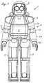
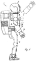
- FIGS 1 to 3 show the overall external appearance of a humanoid robot embodying the present invention.
- This robot 1 is modeled after a lower grade primary school child, and comprises a head 2 incorporated with a visual unit and a speech unit, a body 3 supporting a control unit and incorporated with batteries, and two legs 5 each having joints so as be able to move substantially in the same way as human legs, The robot is thus adapted to walk on two feet.
- This arm 4 comprises a shoulder joint 11 attached to a body 3 so as to be rotatable around a laterally extending axis A1, an upper arm 12 attached to the shoulder joint 11 so as to be rotatable around a fore-and-aft extending axis A2, an elbow joint 13 attached to the upper arm 12 so as to be rotatable around a longitudinal axis A3 of the upper arm 12, a forearm 14 attached to the elbow joint 13 so as to be rotatable around an axis A4 perpendicular to the longitudinal axis A3 of the upper arm 12, and a hand 15 attached to the forearm 14 so as to be rotatable around a longitudinal axis A5 of the forearm 14.
- Each of the rotatable parts is incorporated with a rotary actuator powered by an electric motor, for instance.
- the arm 4 as a whole can be swung in both the forc-and-aft and lateral directions around the shoulder joint 11.
- the forearm 14 can be bent relative to the upper arm 12 via the elbow joint 13, and can also be twisted relative to the upper arm 12.
- both the upper arm 12 and forearm 14 are capable of a twisting motion, and the arm can effect a desired motion by combining these motions.
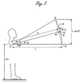
- the maximum error D in the fore-and-aft distance to the object to be accessed due to such a linear approximation can be computed by the equation given below. More specifically, suppose that the axial line passing through the shoulders is C, the center of the hand at the free end of the fully extended arm is P, and the arm is swung around this axial line upward in its fully extended condition until the center of the hand reaches point Q.
- the maximum error D in the fore-and-aft distance to the object to be accessed can be given as the horizontal distance from the center R of the line PQ to the arcuate path (S) of the center of the hand.
- H L sin ⁇ + H 0
- D 910 ⁇ 240 mm
- D may be about 25 mm when a practical precision is considered.
- the present invention is not limited by the particular numerical values of the foregoing embodiment, but may be varied depending of the way the work area is defined. Also, the desirable arm length and the arm swing angle can vary depending on the tolerated error of the fore-and-aft distance of the hand.
- the table given below and the graph given in Figure 7 tabulate and summarize the minimum arm length and arm swing angle for different values of the tolerated distance error.
- the optimum length of the robot arm can be determined, and this allows an arm structure to be constructed which is practical and minimizes the burden on the CPU.
Landscapes
- Engineering & Computer Science (AREA)
- Robotics (AREA)
- Mechanical Engineering (AREA)
- Manipulator (AREA)
Abstract
Description
| work objects | height (mm) |
| office table | 1110 |
| handrail | 1100 |
| facsimile table | 1060 |
| elevator pushbuttons | 1050 |
| door knob | 1050 |
| writing counter | 950 |
| copying machine | 960 |
| high table | 900 |
| counter | 900 |
| telephone | 900 |
| pushcart handle | 840 |
| newspaper rack | 835 |
| | 800 |
| work table | 740 |
| | 700 |
| | 600 |
| | 600 |
| lounge service table | 500 |
| coffee table | 500 |
| wall outlet | 250 |
| bed | 450 |
| maximum error (mm) | arm length (mm) | arm swing angle (degrees) |
| 10 | 754 | ±18.6 |
| 15 | 528 | ±27 |
| 20 | 422 | ±35 |
| 25 | 365 | ±42 |
Claims (7)
- A method for designing an arm structure for a robot having an arm (4) which can rotate vertically and forward over a prescribed angle around an axial line (C) extending substantially between two shoulders, comprising the steps of:defining a vertical extent of a region in front of the robot that can be accessed by the arm (4) in a fully extended state; anddetermining a length (L) of the arm (4) and a height (Ho) of the axis of rotation (C) of the arm (4) in such a manner that a range of rotational motion of the arm (4) in accessing the region can be covered by a range in which the fore-and-aft distance to the tip of the arm can be linearly approximated.
- A method for designing an arm structure for a robot according to claim 1 wherein a height (Ho) of the axis of rotation (C) of the arm (4) is about 910 mm, and the arm (4) is adapted to swing vertically at least by 240 mm at its free end both upward and downward from a horizontal line.
- A method for designing an arm structure for a robot according to claim 2, wherein a maximum tolerated error (D) of the fore-and-aft distance of the free end of the arm (4) is 15 mm, and the arm (4) is at least 528 mm long, and adapted to swing at least ±27 degrees from a horizontal line.
- A method for designing an arm structure for a robot according to claim 2, wherein a maximum tolerated error (D) of the fore-and-aft distance of the free end of the arm (4) is 20 mm, and the arm (4) is at least 422 mm long, and adapted to swing at least ±35 degrees from a horizontal line.
- A method for designing an arm structure for a robot according to claim 2, wherein a maximum tolerated error (D) of the fore-and-aft distance of the free end of the arm (4) is 25 mm, and the arm (4) is at least 365 mm long, and adapted to swing at least ±42 degrees from a horizontal line.
- An arm structure for a robot having an arm (4) which can rotate vertically and forward over a prescribed angle around an axial line (C) extending substantially between two shoulders, wherein:
a height (Ho) of the axis of rotation (C) of the arm (4) is about 910 mm, and the arm (4) is adapted to swing vertically at least by 240 mm at its free end both upward and downward from a horizontal line. - An arm structure for a robot according to claim 6, wherein the arm (4) is at least 365 mm long, and adapted to swing at least ±42 degrees from a horizontal line.
Applications Claiming Priority (2)
| Application Number | Priority Date | Filing Date | Title |
|---|---|---|---|
| JP2000351690 | 2000-11-17 | ||
| JP2000351690 | 2000-11-17 |
Publications (2)
| Publication Number | Publication Date |
|---|---|
| EP1215019A2 true EP1215019A2 (en) | 2002-06-19 |
| EP1215019A3 EP1215019A3 (en) | 2003-01-22 |
Family
ID=18824705
Family Applications (1)
| Application Number | Title | Priority Date | Filing Date |
|---|---|---|---|
| EP01309690A Withdrawn EP1215019A3 (en) | 2000-11-17 | 2001-11-16 | Method for designing a robot arm |
Country Status (2)
| Country | Link |
|---|---|
| US (1) | US6922034B2 (en) |
| EP (1) | EP1215019A3 (en) |
Families Citing this family (9)
| Publication number | Priority date | Publication date | Assignee | Title |
|---|---|---|---|---|
| EP1972416B1 (en) * | 2007-03-23 | 2018-04-25 | Honda Research Institute Europe GmbH | Robots with occlusion avoidance functionality |
| EP1972415B1 (en) * | 2007-03-23 | 2019-01-02 | Honda Research Institute Europe GmbH | Robots with collision avoidance functionality |
| EP1974869A1 (en) * | 2007-03-26 | 2008-10-01 | Honda Research Institute Europe GmbH | Apparatus and method for generating and controlling the motion of a robot |
| JP6332900B2 (en) | 2012-08-31 | 2018-05-30 | セイコーエプソン株式会社 | Robot system and robot controller |
| JP2014205197A (en) | 2013-04-10 | 2014-10-30 | セイコーエプソン株式会社 | Robot, robot control device, and robot system |
| JP2014205198A (en) * | 2013-04-10 | 2014-10-30 | セイコーエプソン株式会社 | Robot, robot control device, and robot system |
| JP2014205199A (en) | 2013-04-10 | 2014-10-30 | セイコーエプソン株式会社 | Robot, robot control device, and robot system |
| JP6155780B2 (en) | 2013-04-10 | 2017-07-05 | セイコーエプソン株式会社 | Robot, robot controller and robot system |
| JP6354122B2 (en) | 2013-06-05 | 2018-07-11 | セイコーエプソン株式会社 | robot |
Family Cites Families (13)
| Publication number | Priority date | Publication date | Assignee | Title |
|---|---|---|---|---|
| DE2228598A1 (en) * | 1972-06-12 | 1974-01-03 | Jens Dr Rer Nat Geerk | ANTHROPOMORPHIC MANIPULATOR |
| US4445184A (en) * | 1980-07-19 | 1984-04-24 | Shin Meiwa Industry Co., Ltd. | Articulated robot |
| JPS59153207A (en) * | 1983-02-21 | 1984-09-01 | Mitsubishi Electric Corp | Control device of robot |
| US4683406A (en) * | 1984-06-08 | 1987-07-28 | Nec Corporation | Joint assembly movable like a human arm |
| US4675502A (en) * | 1985-12-23 | 1987-06-23 | General Electric Company | Real time tracking control for taught path robots |
| US4937759A (en) * | 1986-02-18 | 1990-06-26 | Robotics Research Corporation | Industrial robot with controller |
| EP0254884B1 (en) * | 1986-07-09 | 1990-02-28 | Siemens Aktiengesellschaft | Method to determine the control of a robot by key points in a space |
| JPS63314606A (en) * | 1987-06-18 | 1988-12-22 | Fanuc Ltd | Controller for articulated robot |
| US4990839A (en) * | 1988-12-09 | 1991-02-05 | Schonlau William J | Modular robotic system |
| US4967126A (en) * | 1990-01-30 | 1990-10-30 | Ford Aerospace Corporation | Method of controlling a seven degree of freedom manipulator arm |
| US5430643A (en) * | 1992-03-11 | 1995-07-04 | The United States Of America As Represented By The Administrator Of The National Aeronautics And Space Administration | Configuration control of seven degree of freedom arms |
| US5737500A (en) * | 1992-03-11 | 1998-04-07 | California Institute Of Technology | Mobile dexterous siren degree of freedom robot arm with real-time control system |
| JP3908366B2 (en) * | 1997-12-24 | 2007-04-25 | 本田技研工業株式会社 | Arm structure of humanoid work robot |
-
2001
- 2001-11-16 EP EP01309690A patent/EP1215019A3/en not_active Withdrawn
- 2001-11-16 US US09/988,033 patent/US6922034B2/en not_active Expired - Lifetime
Also Published As
| Publication number | Publication date |
|---|---|
| EP1215019A3 (en) | 2003-01-22 |
| US6922034B2 (en) | 2005-07-26 |
| US20020089296A1 (en) | 2002-07-11 |
Similar Documents
| Publication | Publication Date | Title |
|---|---|---|
| Toxiri et al. | A wearable device for reducing spinal loads during lifting tasks: Biomechanics and design concepts | |
| EP1215019A2 (en) | Method for designing a robot arm | |
| US10039690B2 (en) | Dual muscle roller | |
| US6526331B2 (en) | Robot arm | |
| US7096983B2 (en) | Biped robot | |
| JP2008500093A (en) | Wheelchair with mechanical arm | |
| EP2929821A1 (en) | Electric vacuum cleaner suction tool and electric vacuum cleaner equipped with same | |
| CN111938982A (en) | A massage chair, massage control method thereof, and computer-readable storage medium | |
| KR20180052047A (en) | A joystick type controller assembly of electric wheelchair | |
| US10028577B2 (en) | Ergonomic watchmaker's workstation | |
| KR20210092759A (en) | Device for upper extremity rehabilitation | |
| KR101936850B1 (en) | Rehabilitation apparatus for arm linked to hand exercise | |
| CN209203975U (en) | A kind of touch feedback navigation device based on change in shape | |
| US5690597A (en) | Martial arts exercise apparatus | |
| US20030119638A1 (en) | Horizontally twisting exercising device | |
| CN109395333A (en) | A kind of a kind of multifunctional balanced rehabilitation trainer based on Stewart platform | |
| JP6934659B2 (en) | Motion detection device | |
| KR101366345B1 (en) | Mouse with automatic changing grip angle function for computer | |
| JP2002210683A (en) | Arm structure of upright walking or running robot and design method thereof | |
| CN208974486U (en) | A kind of massage armchair | |
| JP2004016238A (en) | Bench with handrail | |
| JPH0540955Y2 (en) | ||
| CN214072328U (en) | Outdoor portable drawing table | |
| KR101949312B1 (en) | Arm unit for wearable robot | |
| US20070001501A1 (en) | Arm supports |
Legal Events
| Date | Code | Title | Description |
|---|---|---|---|
| PUAI | Public reference made under article 153(3) epc to a published international application that has entered the european phase |
Free format text: ORIGINAL CODE: 0009012 |
|
| AK | Designated contracting states |
Kind code of ref document: A2 Designated state(s): AT BE CH CY DE DK ES FI FR GB GR IE IT LI LU MC NL PT SE TR |
|
| AX | Request for extension of the european patent |
Free format text: AL;LT;LV;MK;RO;SI |
|
| PUAL | Search report despatched |
Free format text: ORIGINAL CODE: 0009013 |
|
| RIC1 | Information provided on ipc code assigned before grant |
Free format text: 7B 25J 18/00 A, 7B 25J 17/02 B |
|
| AK | Designated contracting states |
Kind code of ref document: A3 Designated state(s): AT BE CH CY DE DK ES FI FR GB GR IE IT LI LU MC NL PT SE TR |
|
| AX | Request for extension of the european patent |
Free format text: AL;LT;LV;MK;RO;SI |
|
| 17P | Request for examination filed |
Effective date: 20030514 |
|
| AKX | Designation fees paid |
Designated state(s): DE FR GB |
|
| 17Q | First examination report despatched |
Effective date: 20040826 |
|
| STAA | Information on the status of an ep patent application or granted ep patent |
Free format text: STATUS: THE APPLICATION IS DEEMED TO BE WITHDRAWN |
|
| 18D | Application deemed to be withdrawn |
Effective date: 20130601 |