TECHNICAL FIELD
-
The present invention relates to a suction tool for an electric vacuum cleaner and an electric vacuum cleaner having the suction tool.
BACKGROUND ART
-
There have been made some suggestions on structures of electric vacuum cleaners, particularly on improvement in operability of a vacuum-cleaner suction tool for sucking up dirt.
-
Among such suggestions, for example, Patent List 1 discloses a canister vacuum cleaner having a suction tool formed of a suction-tool body and an adjustable joint of two tubular arms.
-
According to the vacuum-cleaner suction tool of Patent Literature 1, a first arm (of the two arms) is attached to the suction-tool body so as to be rotatable in a direction of elevation angle Y at a first rotative section, whereas a second arm is attached to the remaining end of the first arm so as to be laterally rotatable in the X direction at a second rotative section. The rotational plane of the second rotative section is forwardly inclined at a predetermined angle of Z. Besides, one end of the first arm is attached on the upper side of the rotational plane of the second rotative section, and one end of the second arm is attached on the lower side of the rotational plane. The structure above enables a user to turn the vacuum-cleaner suction tool at an intended angle by handle operation.
-
As another suggestion (for example, see Patent Literature 2), an upright-type floor sweeper is disclosed. The floor sweeper contains a handle having a longitudinal axis, a floor head (suction tool), a support assembly disposed rotatable to the handle, and a link mechanism connecting between the handle and the floor head.
-
Formed like a ball or a roller, the support assembly of the floor sweeper above has rotates on its rotation axis. Further, when the support assembly and the handle are rotated on the longitudinal axis, the link mechanism moves the floor head in a different direction. The structure above enhances operability of the floor sweeper in floor cleaning.
-
The conventional electric vacuum cleaner and floor sweeper described above, however, have to be further improved to achieve satisfying operability of the vacuum-cleaner suction tool.
-
The vacuum-cleaner suction tool of Patent Literature 1 is structured specific to a canister vacuum cleaner, and therefore the suction tool without modification is not compatible to, for example, an upright vacuum cleaner.
-
In a canister vacuum cleaner, generally, one end of the suction hose is connected to the cleaner body and another end of the suction hose is connected to one end of a joint tube. The vacuum-cleaner suction tool is connected to the other end of the joint tube. The cleaner handle is disposed at one end (opposite to the end to which the vacuum-cleaner suction tool is connected) of the joint tube. That is, holding the handle, the user operates the vacuum-cleaner suction tool via the joint tube.
-
The electric vacuum cleaner described in Patent Literature 1 has an arm section formed of a first arm and a second arm and enhances its operability.
-
Unlike the canister-type structure, an upright vacuum cleaner has the cleaner body at a position corresponding to the joint tube of a canister vacuum cleaner. If the structure described in Patent Literature 1 is applied to the upright vacuum cleaner, the user has to operate it together with the heavy and bulky cleaner body, resulting in decrease in operability of the upright vacuum cleaner.
-
According to the floor sweeper described in Patent Literature 2, the vacuum-cleaner suction tool (i.e. floor head) is turned around by vertically inclined rotation axis of the support assembly of a ball or roller shape. This increases the turning radius of the vacuum-cleaner suction tool. That is, to turn the vacuum-cleaner suction tool in a small radius, the user has to give a large twist to the handle. Such a twisting motion places a burden on the wrist of the user. In turning the vacuum-cleaner suction tool in a small radius, as described above, the structure above fails to offer satisfactory operation of the upright vacuum cleaner.
Citation List
Patent Literature
-
- PTL 1: Japanese Unexamined Patent Application Publication No. 11-187993
- PTL 2: Japanese Unexamined Patent Application Publication No. 2006-503608
SUMMARY OF THE INVENTION
-
To address the problems above, the vacuum-cleaner suction tool of the present invention has a suction-tool body with a suction opening formed on one side of a surface to be cleaned, a joint tube section connected to a rear part of the suction-tool body, and a wheel section attached to the joint tube section. The joint tube section has a first tube and a second tube. One end of the first tube is connected to the suction-tool body so as to be movable in the front-to-back direction. One end of the second tube is connected to another end of the first tube so as to be rotatable in the axial direction. The wheel section has a wheel and a wheel supporter for rotatably supporting the wheel at both ends of the supporter. The wheel supporter is movably disposed under the second tube so as to be free for tilt movement about the central part of the wheel supporter as a fulcrum. When the central axis of the tilt movement of the wheel supporter with respect to the second tube is defined as a fixing axis, the fixing axis is set such that the front side is inclined downward along the front-to-back direction of the joint tube section, and fixing-axis angle θ0 formed between the fixing axis forms and the surface to be cleaned is determined to be an acute angle.
-
According to the structure above, the wheel section disposed under the second tube substantially has a three-dimensional inclination by the following movements: tilt of the connecting part between the suction-tool body and the first tube; rotation of the connecting part between the first tube and the second tube; and tilt of the wheel supporter (wheel section) with respect to the second tube. With the structure above, the suction-tool body can be easily turned via the joint tube section. This enhances operability of the vacuum-cleaner suction tool.
-
Besides, the electric vacuum cleaner of the present invention has a cleaner body that produces suction air flow and the aforementioned vacuum-cleaner suction tool.
-
By virtue of improvement in operability of the vacuum-cleaner suction tool in the structure above, when moving the vacuum-cleaner suction tool in a small radius, the user can turn it easily with no need for giving a large twist to the handle of the cleaner body. As a result, the structure reduces a burden on the wrist of the user, while further increasing operability of the vacuum-cleaner suction tool.
BRIEF DESCRIPTION OF DRAWINGS
-
- FIG. 1 is a perspective overall view of a vacuum-cleaner suction tool in accordance with a first exemplary embodiment of the present invention.
- FIG. 2 is a front elevation view of the vacuum-cleaner suction tool in accordance with the first exemplary embodiment.
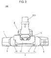
- FIG. 3 is a back elevation view of the vacuum-cleaner suction tool in accordance with the first exemplary embodiment.
- FIG. 4 is a left side view of the vacuum-cleaner suction tool in accordance with the first exemplary embodiment.
- FIG. 5 is a right side view of the vacuum-cleaner suction tool in accordance with the first exemplary embodiment.
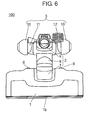
- FIG. 6 is a plain view of the vacuum-cleaner suction tool in accordance with the first exemplary embodiment.
- FIG. 7 is a bottom view of the vacuum-cleaner suction tool in accordance with the first exemplary embodiment.
- FIG. 8 is a cross-sectional view in the front-to-back direction, seen from the left side, of the vacuum-cleaner suction tool in accordance with the first exemplary embodiment.
- FIG. 9 is an explored perspective view of a structure of the wheel section and the wheel fixing section of the vacuum-cleaner suction tool in accordance with the first exemplary embodiment.
- FIG. 10A is a schematic view illustrating the rotational plane of the second tube and the fixing axis of the wheel section of the vacuum-cleaner suction tool in accordance with the first exemplary embodiment.
- FIG. 10B is a schematic view illustrating the fixing axis of the wheel section and the rotation axis of the second tube of the vacuum-cleaner suction tool in accordance with the first exemplary embodiment.
- FIG. 11 is a schematic view of the fixing axis and the rotation axis in a state-where the wheel section substantially has a three-dimensional inclination and the first tube has forward tilt-of the vacuum-cleaner suction tool in accordance with the first exemplary embodiment.
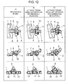
- FIG. 12 is an overall view of the vacuum-cleaner suction tool in the following states in accordance with the first exemplary embodiment: (A) straight-ahead moving; (B) the wheel section has a two-dimensional inclination in leftward turning; (C) the wheel section has a three-dimensional inclination in leftward turning.
- FIG. 13 is an overall view of the vacuum-cleaner suction tool in the following states in accordance with the first exemplary embodiment: (A) straight-ahead moving; (B) the wheel section has a two-dimensional inclination in rightward turning; (C) the wheel section has a three-dimensional inclination in rightward turning.
- FIG. 14A is a left side view in an "in-use" state of the vacuum-cleaner suction tool of the first exemplary embodiment attached to an upright vacuum cleaner.
- FIG. 14B is a left side view in an "in-storage" state of the vacuum-cleaner suction tool of the first exemplary embodiment attached to an upright vacuum cleaner.
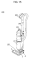
- FIG. 15 is a perspective overall view of a structure in which the vacuum-cleaner suction tool of a second exemplary embodiment is applied to an upright vacuum cleaner.
- FIG. 16 is a perspective overall view of a structure in which the vacuum-cleaner suction tool of a third exemplary embodiment is applied to a canister vacuum cleaner.
DESCRIPTION OF EMBODIMENTS
-
Hereinafter, the vacuum-cleaner suction tool of the exemplary embodiments of the present invention will be described in detail with reference to the accompanying drawings. Through the description below, like parts have similar reference marks and an overlapped description will be omitted.
FIRST EXEMPLARY EMBODIMENT
-
First, an overall structure of vacuum-cleaner suction tool 100 of the first exemplary embodiment will be described with reference to FIG. 1 through FIG. 8.
-
FIG. 1 is a perspective overall view of a vacuum-cleaner suction tool of the first exemplary embodiment of the present invention. FIG. 2 is a front elevation view of the vacuum-cleaner suction tool of the exemplary embodiment. FIG. 3 is a back elevation view of the vacuum-cleaner suction tool of the exemplary embodiment. FIG. 4 is a left side view of the vacuum-cleaner suction tool of the exemplary embodiment. FIG. 5 is a right side view of the vacuum-cleaner suction tool of the exemplary embodiment. FIG. 6 is a plain view of the vacuum-cleaner suction tool of the exemplary embodiment. FIG. 7 is a bottom view of the vacuum-cleaner suction tool of the exemplary embodiment. FIG. 8 is a cross-sectional view in the front-to-back direction, seen from the left side, of the vacuum-cleaner suction tool of the exemplary embodiment.
-
As shown in FIG. 1 through FIG. 8, vacuum-cleaner suction tool 100 of the exemplary embodiment has at least suction-tool body 1, joint tube section 2, and wheel section 3.
-
As shown in FIGS. 1, 2, 6, and 7, suction-tool body 1 is formed into a long plate. Joint tube section 2 is connected at a backward position in the middle of suction-tool body 1 in the lengthwise direction.
-
Throughout the description on positional relation of the components of the exemplary embodiment, the "front" means the side on which suction-tool body 1 of vacuum-cleaner suction tool 100 is disposed, and the "back" means the side on which wheel section 3 is disposed; similarly, the "left" is the leftward with respect to the direction in which vacuum-cleaner suction tool 100 faces forward, and the "right" is the rightward with respect to the aforementioned direction.
-
As shown in FIG. 7 and FIG. 8, suction-tool body 1 has suction opening 1a in a front position on the lower side (i.e., the side facing a surface to be cleaned), and dirt on a surface is sucked up through suction opening 1a. Suction opening 1a has a rectangular shape in the lengthwise direction of suction-tool body 1 and contains rotating brush 4 therein. Rotating brush 4 is formed into, for example, a cylinder, and is rotated by a brush-rotating mechanism (not shown). Driven on a motor or an air turbine, the brush-rotating mechanism (not shown) rotates rotating brush 4.
-
Besides, as shown in FIGS. 4, 5, 7, and 8, for example, a pair of front wheels 5 on the right and left and a pair of back wheels 6 on the right and left are disposed on the bottom of suction-tool body 1. Front wheels 5 are disposed between suction opening 1a and back wheels 6 at a position adjacent to suction opening 1a. Back wheels 6 are disposed at a position adjacent to joint tube section 2 in the back of suction-tool body 1. Front wheels 5 and back wheels 6 move suction-tool body 1 on the surface to be cleaned. Although the exemplary embodiment describes a structure in which front wheels 5 are disposed between suction opening 1a and back wheels 6 at a position adjacent to suction opening 1a, it is not limited to; for example, front wheels 5 may be disposed between suction opening 1a and the front edge 1b and at a position close to suction opening 1a on the bottom surface of suction-tool body 1.
-
As shown in FIG. 1 and FIG. 4 through FIG. 8, joint tube section 2 is connected to the back of suction-tool body 1. According to the exemplary embodiment, joint tube section 2 is formed of first tube 7, second tube 8, and third tube 9.
-
One end of first tube 7 of joint tube section 2 is connected to the backward upper section of suction-tool body 1 so as to be movable in the front-to-back direction of suction-tool body 1. One end of second tube 8 of joint tube section 2 is connected to another end of first tube 7 so as to be turnable in the horizontal direction with respect to the axial direction. One end of third tube 9 of joint tube section 2 is connected to another end of second tube 8 so as to be movable in the front-to-back direction, and another end of third tube 9 is an open end connectable to an electric vacuum cleaner. Besides, as shown in FIG. 1, third tube 9 may contain protrusion 9a that rotates with the movement of third tube 9. Protrusion 9a functions as a stop against tilting movement of wheel section 3.
-
In the description of the exemplary embodiment, as shown in FIG. 1, the tilting direction of first tube 7 is represented by arrow M1, the rotating direction of second tube 8 is represented by arrow M2, the tilting direction of third tube 9 is represented by arrow M3, and the rotating direction of wheel section 3 is represented by arrow M4. Specifically, vacuum-cleaner suction tool 100 shown in FIG. 1 is in an "in-storage" state (that will be described later) where third tube 9 is inclined to the maximum limit in the forward direction. This is because arrow M3 in FIG. 1 shows that third tube 9 can move in the backward direction only.
-
Although the exemplary embodiment describes the structure of joint tube section 2 formed of three tubular members: first tube 7; second tube 8; and third tube 9, it is not limited to. Joint tube section 2 may be formed of, for example, four or more tubular members as necessary, and may contain a member other than tubular members. The tilting or rotating movement and other functions of first tube 7, second tube 8, and third tube 9 forming joint tube section 2 will be described later.
-
Wheel section 3 is disposed on joint tube section 2. Wheel section 3 is formed of a pair of wheels 10 disposed on the left and right, wheel supporter 11, and lever mechanism 12. Rotating wheel section 3 together with front wheels 5 and back wheels 6 disposed on the bottom of suction-tool body 1 allows vacuum-cleaner suction tool 100 to move on the surface to be cleaned. Wheels 10 are rotatably held at both ends of wheel supporter 11.
-
The shape of wheels 10 is not specifically limited, as long as heretofore-known one. According to the exemplary embodiment, as shown in FIG. 3, FIG. 6, and FIG. 7, wheels 10 have a shape such that the outer diameter of each wheel decreases from the inner side (on the side held by wheel supporter 11) toward the outer side. That is, the wheel has a section of parabolic or substantially parabolic, for example. Compared to the inner side (i.e., the side facing joint tube section 2), the shape tapers toward the outer side, protruding the center of the wheel. If vacuum-cleaner suction tool 100 tilts in a direction when rotated, the wheel with the tapered surface rotates while having contact with the surface to be cleaned. That is, the tapered shape of the wheel allows wheels 10-even in an inclined state-to rotate with a smooth movement on the surface to be cleaned. As a result, vacuum-cleaner suction tool 100 enhances its operability.
-
Wheel supporter 11 for wheel section 3, as shown in FIG. 3 and FIG. 7, is formed into a long plate whose lengthwise side is shorter than that of suction-tool body 1. Wheel supporter 11 holds a pair of wheels 10 rotatably at the both ends. The central part of wheel supporter 11 is fixed to joint tube section 2 via wheel fixing section 13. As shown in FIG. 6 and FIG. 7, wheel supporter 11 is basically disposed orthogonal to the extending direction (i.e. the front-to-back direction) of joint tube section 2. However, wheel supporter 11 is tiltable to joint tube section 2 in the "in-use" state (i.e., when the suction tool sucks up dirt while being attached to an electric vacuum cleaner).
-
When vacuum-cleaner suction tool 100 is not used, particularly in the "in-storage" state, lever mechanism 12 of wheel section 3 works as a stop against tilt movement of third tube 9 and wheel section 3. Specifically, when vacuum-cleaner suction tool 100 is in the "in-use" state, third tube 9 usually lies down backward. To put vacuum-cleaner suction tool 100 into the "in-storage" state from the "in-use" state, the user raises third tube 9 forward, and at that time, lever mechanism 12 is pushed up in response to the tilt movement of third tube 9. Lever mechanism 12 thus puts a limit on the tilt movement of third tube 9 and wheel section 3. A specific structure of lever mechanism 12 and the limiting function on the tilt movement of wheel section 3 will be described later.
-
The exemplary embodiment describes a structure of wheel section 3 having wheels 10, wheel supporter 11, and lever mechanism 12; but it is not limited to. For example, wheel section 3 may be formed of at least wheels 10 and wheel supporter 11. Lever mechanism 12 is for suppressing the tilt movement of wheel supporter 11. Wheel section 3 may additionally contain a "tilt-stop" mechanism or member other than lever mechanism 12. Further, wheel section 3 may have a different structure other than that having wheels 10, wheel supporter 11, and lever mechanism 12.
-
As shown in FIG. 1, FIG. 3 through FIG. 5, FIG. 7, and FIG. 8, wheel fixing section 13 for fixing wheel supporter 11 to joint tube section 2 is disposed under joint tube section 2. In the exemplary embodiment, wheel fixing section 13 is disposed under second tube 8, that is, wheel supporter 11 (i.e. wheel section 3) is fixed to second tube 8 of joint tube section 2. Further, wheel supporter 11 is structured so as to be tiltable on the central part of wheel fixing section 13 as a fulcrum.
-
As for suction-tool body 1, joint tube section 2, and wheel section 3 described above, the further specific structures, such as material, dimensions, and components of them have no particular limitation; a structure heretofore known in the field of the vacuum cleaner may be employed. For example, suction-tool body 1 and joint tube section 2 may be an assembly of a resin product having a heretofore-known structure. Rotating brush 4 may have a heretofore-known structure in which resin-made bristles (not shown) are attached to a cylindrical member of resin-molded material. Front wheels 5, back wheels 6, and wheels 10 also may be an assembly of resin-molded materials; preferably, they should be formed of elastic material such as rubber.
-
Hereinafter, detailed structures of the wheel section and the wheel fixing section of the vacuum-cleaner suction tool of the exemplary embodiment will be described with reference to FIG. 1 through FIG. 9.
-
FIG. 9 is an explored perspective view of a structure of the wheel section and the wheel fixing section of the vacuum-cleaner suction tool of the first exemplary embodiment.
-
As shown in FIG. 8 and FIG. 9, wheel fixing section 13 of vacuum-cleaner suction tool 100 is at least formed of first torsion spring 14, second torsion spring 15, fixing body 16, fixing shaft 17, and shaft fastener 18.
-
First torsion spring 14 is disposed in the back of wheel fixing section 13, whereas second torsion spring 15 is disposed in front of wheel fixing section 13. Each of first torsion spring 14 and second torsion spring 15 is an identically-shaped torsion coil spring (torsion spring) formed of spring body 19, first arm 20, and second arm 21. Spring body 19 is, for example, a steel wire wound around like a coil. First arm 20 and second arm 21 linearly extend at each end of spring body 19.
-
To be specific, first arm 20 extends from a point on the outer circumference of round spring body 19 toward a direction of tangent, and is exposed at fixing body 16 so as to be rotatable. That is, first arm 20 makes contact with the outer circumference of second tube 8 and rotates with the rotation of second tube 8. In contrast, second arm 21 extends in the winding direction (i.e., in the axial direction of the coil) at the other end of spring body 19. While being accommodated in fixing body 16, second arm 21 functions as a stop that puts a restraint on a rotation range of first torsion spring 14 and second torsion spring 15.
-
As shown in FIG. 9, fixing body 16, for example, has a cylindrical structure and is integrally fixed to the central part of wheel supporter 11. First torsion spring 14 and second torsion spring 15 are accommodated in fixing body 16. Specifically, first torsion spring 14 is accommodated on the rear side (i.e. in a back part) of fixing body 16, whereas second torsion spring 15 is accommodated on the front side (i.e. in a front part) of fixing body 16.
-
Fixing shaft 17 has shaft body 22 having a cylindrical or substantially cylindrical shape and lid plate 23 disposed at the back end of shaft body 22. Fixing shaft 17 has a shape like a bolt or a nail.
-
As shown in FIG. 8, fixing shaft 17 is inserted into fixing body 16; at that time, fixing shaft 17 runs through first torsion spring 14 and second torsion spring 15 disposed in fixing body 16 and supports them from inside.
-
At that time, as shown in FIG. 9, fixing shaft 17 is inserted into fixing body 16 from the back (i.e. from the rear side). As shown in FIG. 8, lid plate 23 disposed at the back end of fixing shaft 17 functions as a lid member for covering the opening formed on the rear side of fixing body 16.
-
As shown in FIG. 9, downwardly-protruded shaft insertion frame 24 is disposed on the lower side of second tube 8. As shown by a dash-single-dot line in FIG. 9, fixing shaft 17 is inserted into shaft insertion flame 24 and then inserted into fixing body 16. Such structured fixing shaft 17 functions as a fixing member to fix wheel fixing section 13 to second tube 8.
-
As shown in FIG. 9, shat fastener 18 is formed of tip receptor 25 that fits the tip of fixing shaft 17 and outer attachment 26 attached to the outer circumference of second tube 8. Fixing shaft 17 is inserted into fixing body 16 and the tip of fixing shaft 17 is fitted in tip receptor 25, by which fixing shaft 17 is securely fastened to fixing body 16. Further, outer attachment 26 of shaft fastener 18 is attached to second tube 8. Through the procedures above, the both ends of fixing shaft 17 and fixing body 16 are fixed to second tube 8. To be specific, the back end (the rear side) of fixing body 16 is fixed to second tube 8 by fixing shaft 17 inserted into shaft insertion frame 24; on the other hand, the front end (the front side) of fixing body 16 is fixed to second tube 8 by shaft fastener 18 (in which the tip of fixing shaft 17 is fitted) attached to the outer circumference of second tube 8.
-
In this way, wheel fixing section 13 of the exemplary embodiment is integrally disposed on wheel supporter 11 of wheel section 3. The structure above allows wheel section 3 to rotate in a direction shown by arrow M4 (in FIG. 1) on central axis S4 (indicated by broken lines in FIG. 8) of first torsion spring 14 and second torsion spring 15 i.e., on central axis S4 of rotation of wheel supporter 11. Aforementioned central axis S4 of rotation of wheel section 3 is hereinafter referred to as "fixing axis S4" for the sake of convenience since central axis S4 is also the axis in the fixing direction of wheel fixing section 13.
-
According to the exemplary embodiment, each second arm 21 of first torsion spring 14 and second torsion spring 15 functions as a stop that puts a restraint on the rotation range of them. Therefore, the "rotation" of wheel section 3 by wheel fixing section 13 is not a complete one turn of wheel section 3 but a partial turn, specifically, wheel section 3 have a tilt under second tube 8. Besides, first torsion spring 14 and second torsion spring 15 urge second tube 8 tilted with a tilt movement of wheel supporter 11 (i.e., wheel section 3) to move oppositely (i.e., toward the original position), which will be described later.
-
First torsion spring 14, second torsion spring 15, fixing body 16, fixing shaft 17, and shaft fastener 18 of the exemplary embodiment are not limited to a specific structure. For example, first torsion spring 14 and second torsion spring 15 may be a heretofore known steel torsion spring. Fixing body 16, fixing shaft 17, and shaft fastener 18 may be heretofore known resin-molded components, like wheel section 3.
-
Hereinafter, an example of usage of vacuum-cleaner suction tool 100-together with the positional relationship of suction-tool body 1, joint tube section 2, and wheel section 3-of the exemplary embodiment will be described with reference to FIG. 10A through FIG. 13.
-
FIG. 10A is a schematic view illustrating the rotational plane of the second tube and the fixing axis of the wheel section of the vacuum-cleaner suction tool of the first exemplary embodiment of the present invention. FIG. 10B is a schematic view illustrating the fixing axis of the wheel section and the rotation axis of the second tube of the vacuum-cleaner suction tool of the exemplary embodiment. FIG. 11 is a schematic view of the fixing axis and the rotation axis in a state where the wheel section substantially has a three-dimensional inclination and the first tube has forward tilt of the vacuum-cleaner suction tool of the exemplary embodiment. FIG. 12 is an overall view of the vacuum-cleaner suction tool in the following states of the exemplary embodiment: (A) straight-ahead moving; (B) the wheel section has a two-dimensional inclination in leftward turning; (C) the wheel section has a three-dimensional inclination in leftward turning. FIG. 13 is an overall view of the vacuum-cleaner suction tool in the following states in accordance with the first exemplary embodiment: (A) straight-ahead moving; (B) the wheel section has a two-dimensional inclination in rightward turning; (C) the wheel section has a three-dimensional inclination in rightward turning.
-
Each of FIG. 10A and FIG. 10B is a schematic view showing each axis and each angle (that will be described later) under a condition in which vacuum-cleaner suction tool 100 is similarly placed on surface F to be cleaned. Further, each of FIG. 10A and FIG. 10B illustrates the "in-use" state where third tube 9 has a backward tilt. In addition to the "in-use" state, FIG. 10A shows the "in-storage" state (in dotted lines) where third tube 9 is raised up and positioned at the maximum limit in the forward direction of suction-tool body 1. Further, FIG. 11 shows an "in-use" state where wheel section 3 disposed under second tube 8 substantially has a three-dimensional inclination and first tube 7 is positioned at the maximum limit in the forward direction of suction-tool body 1. Broken lines in FIG. 11 partly show the position of first tube 7 and second tube 8 when vacuum-cleaner suction tool 100 shown in FIGS. 10A and 10B is placed on surface F to be cleaned (where a pair of wheels 10 on the left and right makes contact with surface F). Each of FIG. 12 and FIG. 13 illustrates vacuum-cleaner suction tool 100 in an "in-use" state, showing a top view at the top; a left side view at the middle; and a back view at the bottom.
-
As shown in FIG. 10A and FIG. 10B, one end of first tube 7 of joint tube section 2 is connected to the backward upper section of suction-tool body 1 so as to be tiltable in the front-to-back direction of suction-tool body 1. At that time, tilt axis S1 (i.e., the central axis of tilt of first tube 7 in the front-to-back direction of suction-tool body 1) is parallel to surface F in the lengthwise direction of suction-tool body 1.
-
Further, one end of second tube 8 of joint tube section 2 is connected to another end of first tube 7 so as to be axially rotatable. At that time, as shown in FIG. 10B, rotation axis S2 (i.e., the central axis of rotation of second tube 8 with respect to first tube 7) has a downward inclination on the back side in the front-to-back direction of joint tube section 2. In the exemplary embodiment, a plane on which second tube 8 turns with respect to first tube 7 is described as rotational plane P0.
-
Further, one end of third tube 9 of joint tube section 2 is connected to another end of second tube 8 so as to be tiltable in the front-to-back direction of joint tube section 2. In the structure above, joint-tube tilt axis S3 (i.e., the central axis of tilt of third tube 9 in the front-to-back direction of joint tube section 2) is parallel to surface F in the lengthwise direction of suction-tool body 1.
-
On the lower surface of second tube 8 of joint tube section 2, wheel fixing section 13-to which wheel supporter 11 is fixed so as to be rotatable (tiltable)-is disposed. In the structure above, fixing axis S4 of wheel supporter 11 of wheel section 3, which agrees with the fixing direction of wheel fixing section 13, has a downward inclination on the front side in the front-to-back direction of joint tube section 2.
-
The degree of inclination of fixing axis S4 is not particularly limited, but preferably, it should be determined so that fixing axis S4 makes an acute angle with surface F. Such structured vacuum-cleaner suction tool 100 further enhances its operability.
-
Specific description will be given below. In a state where vacuum-cleaner suction tool 100 is placed on surface F, suppose that the angle which fixing axis S4 forms with surface F is determined as fixing-axis angle θ0, as shown in FIG. 10A and FIG. 10B. Preferably, fixing-axis angle θ0 should be an acute angle (less than 90°); more preferably, should be in a range from 5° to 45°.
-
That is, when fixing-axis angle θ0 is an acute angle, wheel supporter 11 inclines by wheel fixing section 13 partly rotated (tilted) on fixing axis S4. When wheel section 3 has a partial rotation (tilt) on fixing axis S4 of wheel fixing section 13, wheel supporter 11 inclines. At that time, either one of a pair of wheels 10 is positioned forward, as shown in FIG. 12(B) and FIG. 12(C), or in FIG. 13(B) and FIG. 13(C). For example, FIG. 12(B) and FIG. 12(C) show the inclination of wheel supporter 11 where the left wheel of wheels 10 is positioned anterior to the right wheel. In contrast, FIG. 13(B) and FIG. 13(C) show the inclination of wheel supporter 11 where the right wheel of wheels 10 is positioned anterior to the left wheel.
-
Wheel supporter 11 rotates on fixing axis S4 of wheel fixing section 13 (i.e., wheel supporter 11). When rotating to some extent, wheel supporter 11 has a planar (two-dimensional) inclination where the left or the right wheel (of a pair of wheels 10) moves forward. When rotating further, wheel supporter 11 has a stereoscopic (three-dimensional) inclination where the anteriorly-located wheel 10 has a low position and the posteriorly-located wheel 10 has a high position. For example, FIG. 12(B) and FIG. 12(C) show that leftward rotation of wheel supporter 11 on fixing axis S4 moves left wheel 10 forward and therefore wheel supporter 11 inclines. Similarly, FIG. 13(B) and FIG. 13(C) show that rightward rotation of wheel supporter 11 on fixing axis S4 moves right wheel 10 forward and therefore wheel supporter 11 inclines.
-
When each figure in the top of FIG. 12 and FIG. 13 is seen as a plain view shown in FIG. 6 (i.e., when vacuum-cleaner suction tool 100 is seen from above), the aforementioned rotation moves any one of wheels 10 forward, and at the same time, joint tube section 2 inclines in a direction of the moved wheel. Specifically, when left wheel 10 moves forward and wheel supporter 11 inclines, joint tube section 2 inclines on the left (FIG. 12). Similarly, when right wheel 10 moves forward and wheel supporter 11 inclines, joint tube section 2 inclines on the right (FIG. 13).
-
According to the exemplary embodiment, in addition to the aforementioned structure having fixing axis S4 of wheel supporter 11, wheel section 3 is fixed to second tube 8 via wheel supporter 11 and wheel fixing section 13. Through the structure above, one end of first tube 7 is connected to the backward upper section of suction-tool body 1 so as to be tiltable in the front-to-back direction of suction-tool body 1. Further, one end of second tube 8 is connected to another end of first tube 7 so as to be rotatable in the axial direction. Through the connection, rotation of second tube 8 inclines wheel supporter 11 (wheel section 3) and tilts first tube 7. The rotation of second tube 8 is thus carried to suction-tool body 1.
-
To be specific, when second tube 8 is turned to the left, as shown in FIG. 12(B), from the straight-ahead state shown in FIG. 12(A), the movement of second tube 8 turns wheel supporter 11 with inclination having a positional relation between left wheel 10 located forward and right wheel 10 located backward. Further, the movement of second tube 8 tilts first tube 7, so that suction-tool body 1 turns to the left.
-
When second tube 8 is further turned to the left, as shown in FIG. 12(C), from the state above shown in FIG. 12(B), the movement of second tube 8 turns wheel supporter 11 with a three-dimensional inclination. At that time, the movement of second tube 8 moves left wheel 10 further forward from the position shown in FIG. 12(B) and moves right wheel 10 further backward and upward from the position shown in FIG. 12(B). The movement of second tube 8 tilts first tube 7, so that suction-tool body 1 turns further to the left.
-
Similarly, when second tube 8 is turned to the right shown in FIG.13(A) and FIG. 13(B) from the straight-ahead state shown in FIG. 13(A), the movement of second tube 8 turns wheel supporter 11 with inclination having a positional relation between right wheel 10 located forward and left wheel 10 located backward. Further, the movement of second tube 8 tilts first tube 7, so that suction-tool body 1 turns to the right.
-
When second tube 8 is further turned to the right shown in FIG.11 and FIG. 13(C) from the straight-ahead state shown in FIG. 13(B), the movement of second tube 8 turns wheel supporter 11 with a three-dimensional inclination. At that time, the movement of second tube 8 moves right wheel 10 further forward from the position shown in FIG. 13(B) and moves left wheel 10 further backward and upward from the position shown in FIG. 13(B). The movement of second tube 8 tilts first tube 7, so that suction-tool body 1 turns further to the right.
-
With the structure above, wheel supporter 11 (wheel section 3) and first tube 7 turn with the movement of second tube 8, by which suction-tool body 1 turns. The structure improves operability of vacuum-cleaner suction tool 100.
-
In the structure of the exemplary embodiment, one end of first tube 7 is connected to suction-tool body 1 so as to be tiltable. When second tube 8 is turned further from the state of FIG. 12(B) to the state of FIG. 12(C), or from the state of FIG. 13(B) to the state of FIG. 11 and FIG. 13(C), the turning movement of second tube 8 moves first tube 7 in the forward direction of suction-tool body 1 from the broken-line position (shown in FIG. 11) to the solid-line position. That is, when second tube 8 is turned further from the state of FIG. 12(B) to the state of FIG. 12(C), or from the state of FIG. 13(B) to the state of FIG. 11 and FIG. 13(C), anteriorly-located wheel 10 moves further forward from the position shown in FIG. 12(B) and FIG. 13(B), and posteriorly-located wheel 10 moves backward and upward from the position shown in FIG. 12(B) and FIG. 13(B). According to the structure of the embodiment, however, the tilt of first tube 7 absorbs the movement of first tube 7 and second tube 8 caused by the positional change of wheels 10 (i.e., inclined wheel section 3). Therefore, even when second tube 8 is turned from the state of FIG. 12(B) to the state of FIG. 12(C), or from the state of FIG. 13(B) to the state of FIG. 11 and FIG. 13(C), suction-tool body 1 maintains contact with surface F. This allows suction-tool body 1 and surface F to have an airtight contact therebetween. As a result, vacuum-cleaner suction tool 100 maintains suction performance with stability.
-
Hereinafter, the workings of an electric vacuum cleaner having the vacuum-cleaner suction tool of the exemplary embodiment will be described.
-
First, the user operates lever mechanism 12 to lay back third tube 9 to some extent from the "raised-up" state (where third tube 9 is positioned at the maximum limit on the front side), as shown in FIG. 1 through FIG. 8. The user operation allows the vacuum cleaner to be ready for use, as shown in FIG. 10A, FIG. 10B, FIG. 12(A), and FIG. 13(A). At that time, wheel supporter 11 (wheel section 3) is parallel (or substantially parallel) to suction-tool body 1.
-
Next, the user turns suction-tool body 1 from the aforementioned state to start cleaning. Specifically, the user gives a little twist to the handle of the vacuum cleaner to turn suction-tool body 1 as shown in FIG. 12(B) and FIG. 13(B). The movement also turns wheel supporter 11 and second tube 8 with inclination. The three-dimensional movement brought by the turning above is carried to suction-tool body 1 via first tube 7, so that suction-tool body 1 turns in a direction in which second tube 8 inclines. Through the processes, the user can easily operate vacuum cleaner suction tool 100.
-
Next, to further turn suction-tool body 1 from the state shown in FIG. 12(B) and FIG. 13(B), the user further gives a twist to the handle of the vacuum cleaner. At that time, vacuum cleaner suction tool 100 turns, as shown in FIG. 12(C) and FIG. 13(C). The movement also turns wheel supporter 11 and second tube 8 with further inclination. The three-dimensional movement brought by the turning above is carried to suction-tool body 1 via first tube 7, so that suction-tool body 1 further turns in a direction in which second tube 8 inclines. Through the processes, the user can easily turn vacuum cleaner suction tool 100.
-
In the turning operation of suction-tool body 1, as shown in FIGS. 12(B), 12(C), 13(B), and 13(C), one end of suction-tool body 1 comes close to one of wheels 10 of wheel section 3. For example, when suction-tool body 1 is turned to the left, the left end of suction-tool body 1 comes close to the left wheel of wheels 10, as shown in FIGS. 12(B) and 12(C); similarly, when suction-tool body 1 is turned to the right, the right end of suction-tool body 1 comes close to the right wheel, as shown in FIGS. 13(B) and 13(C). At that time, wheel section 3 moves such that the wheel located opposite to the turning direction moves backward, allowing suction-tool body 1 to turn in an intended direction.
-
The exemplary embodiment describes the structure of suction-tool body 1, taking an example in which aforementioned fixing-axis angle θ0 of fixing axis S4 is defined, but it is not limited to. For example, the position of wheel fixing section 13 with reference to third tube 9 may be defined. Specifically, as shown in FIG. 10A and FIG. 10B, third tube 9 is connected to second tube 8 so as to be tiltable in tilt direction M3 that agrees with the front-to-back direction. When the central axis of tilt direction M3 is defined as joint-tube tilt axis S3, it extends along the horizontal direction (i.e., the lengthwise direction of suction-tool body 1).
-
In the structure of the exemplary embodiment, preferably, wheel fixing section 13 should be located ahead of joint-tube tilt axis S3. Locating wheel fixing section 13 at such a position appropriately defines the distance between wheel section 3 and suction-tool body 1. With the structure above, wheel section 3 disposed under second tube 8 substantially has a three-dimensional inclination as a result of the following movements of the components: tilt movement of the connecting section between suction-tool body 1 and first tube 7; turning movement of the connecting section between first tube 7 and second tube 8; and inclination of wheel supporter 11 (wheel section 3). As a result, inclined wheel supporter 11 (wheel section 3) allows suction-tool body 1 to have an appropriate turn via joint tube section 2.
-
The exemplary embodiment describes an example having the structure in which aforementioned fixing axis S4 of wheel fixing section 13, i.e., fixing-axis angle θ0 of fixing axis S4 of wheel supporter 11 is defined, but it is not limited to. For example, the connection angle formed between first tube 7 and second tube 8 may be defined. In that case, in a state where vacuum-cleaner suction tool 100 is placed on surface F, suppose that a plane on which second tube 8 turns with respect to first tube 7 is defined as rotational plane P0. Like in the case of determining fixing-axis angle θ0 that defines inclination of fixing axis S4, rotational-plane fixing angle θ1 formed between rotational plane P0 and fixing axis S4 is determined in a preferable range. In this way, rotational-plane fixing angle θ1, which is the connection angle between first tube 7 and second tube 8, can be defined.
-
Under the state where vacuum-cleaner suction tool 100 is placed on surface F, as shown in FIG. 10A, suppose that a plane on which second tube 8 turns with respect to first tube 7 is defined as rotational plane P0, and the angle formed between rotational plane P0 and fixing axis S4 of wheel supporter 11 is defined as rotational-plane fixing angle θ1. In the structure above, rotational-plane fixing angle θ1 is determined to be an acute angle (less than 90°). When rotational-plane fixing angle θ1 is an acute angle (less than 90°), wheel supporter 11 turns with inclination on fixing axis S4 of wheel supporter 11. Therefore, when second tube 8 turns while having inclination, rotational plane P0 inclines in the direction in which second tube 8 inclines. The torque produced by the turning movement of second tube 8 and rotational plane P0 is applied to first tube 7 so that first tube 7 turns in the turning direction of second tube 8. According to the structure of the exemplary embodiment, one end of first tube 7 is fixed to suction-tool body 1 so as to be tiltable in the front-to-back direction only (i.e., so as not to be tiltable in the horizontal direction of suction-tool body 1), and one end of second tube 8 is connected to another end of first tube 7 so as to have turning movement in the axial direction. Through the structure above, the turning movement of second tube 8 and rotational plane P0 is effectively carried to suction-tool body 1 via first tube 7, and suction-tool body 1 can be easily turned in the turning direction of second tube 8. As a result, the user can effectively turn suction-tool body 1 (i.e., vacuum-cleaner suction tool 100) in the horizontal direction.
-
The exemplary embodiment describes the structure taking following examples: one case in which fixing-axis angle θ0 of fixing axis S4 is defined, and the other case in which rotational-plane fixing angle θ1 is defined, but it is not limited to. For example, the angle formed between rotational plane P0 and surface F may be defined. Specifically, suppose that the angle formed between rotational plane P0 of second tube 8 and surface F is defined as rotational-plane angle θ2, as shown in FIG. 10A. At that time, rotational-plane angle θ2 is defined to be greater than fixing-axis angle θ0 but an acute angle (less than 90°). By virtue of the definition above, second tube 8 is connected to first tube 7 so as to have a backward tilt with respect to first tube 7. When second tube 8 is turned by inclined wheel section 3, the torque produced by the turning movement is applied to first tube 7 obliquely upward. At that time, according to the exemplary embodiment, first tube 7 is fixed to suction-tool body 1 so as to be tiltable in the front-to-back direction only (see tilt direction M1 shown in FIG. 10A). The structure effectively carries the turning movement of second tube 8 to suction-tool body 1. As a result, the user can easily turn suction-tool body 1 in the horizontal direction.
-
In the structure above, defining inclination by fixing-axis angle θ0 of fixing axis S4 and defining the connection angle between second tube 8 and first tube 7 also means defining the relationship of inclination between second tube 8 and wheel fixing section 13. That is, wheel fixing section 13 and second tube 8 are disposed in the front-to-back direction. Wheel fixing section 13 is disposed so as to have an upward inclination toward the back. Further, rotation axis S2 of first tube 7 and second tube 8 is disposed so as to have an upward inclination toward the front.
-
That is, as shown in FIG. 10B, rotation axis S2-which is the center of turning movement of second tube 8 with respect to first tube 7 (and corresponds to the direction of normal line of rotational plane P0)-and fixing axis S4 of wheel fixing section 13 have a relationship of crossing with each other. Specifically, as shown in FIG. 10B, rotation-axis angle θ3 formed between rotation axis S2 and surface F should be an acute angle (less than 90°); more preferably, should be in a range from 5° to 45°.
-
That is, when fixing axis S4 of wheel fixing section 13 (i.e. wheel supporter 11) and rotation axis S2 of second tube 8 are defined so as to have a crossing relationship, second tube 8 turns in direction M2 of FIG. 10B while having appropriate inclination with the movement of wheel section 3.
-
In the structure of the exemplary embodiment, second tube 8 is connected to first tube 7, and first tube 7 is connected to suction-tool body 1 so as to be tiltable on tilt axis S1 in tilt direction M1. That is, from a point of view on the side of first tube 7, suction-tool body 1 is connected to first tube 7 so as to be tiltable in the front-to-back direction. Therefore, the tilt movement of first tube 7 in tilt direction M1 and the turning movement of second tube 8 in turning direction M2 are transmitted as a combined movement to suction-tool body 1, which allows suction-tool body 1 to have effective turns.
-
The description below is on the positional relationship between fixing axis S4 of wheel fixing section 13 (i.e. wheel supporter 11), rotation axis S2 of second tube 8, and joint-tube tilt axis S3 of third tube 9.
-
Fixing axis S4 and rotation axis S2 are on the same plane, and joint-tube tilt axis S3 extends in a direction perpendicular to the plane. That is, joint-tube tilt axis S3 corresponds to a normal line to the plane having fixing axis S4 and rotation axis S2. Joint-tube tilt axis S3 has no direct intersection with fixing axis S4 and rotation axis S2; they have a skewed relation.
-
In the structure of the exemplary embodiment, wheel fixing section 13 fixes wheel supporter 11 on the lower side of second tube 8 of joint tube section 2 so as to be tiltable. With structure above, wheel section 3 disposed under second tube 8 substantially has a three-dimensional inclination by the following movements: tilt of the connecting part between suction-tool body 1 and first tube 7; rotation of the connecting part between first tube 7 and second tube 8; and tilt of wheel supporter 11 (wheel section 3) by wheel fixing section 13. Suction-tool body 1 can be easily turned by such inclined wheel section 3 via joint tube section 2. This enhances operability of vacuum-cleaner suction tool 100.
-
Hereinafter, vacuum-cleaner suction tool 100 of the exemplary embodiment will be described, taking an example in which vacuum-cleaner suction tool 100 is mounted on cleaner body 201 of upright vacuum cleaner 200, with reference to FIG. 14A and FIG. 14B. Specifically, a load to be applied to vacuum-cleaner suction tool 100 mounted on upright vacuum cleaner 200.
-
FIG. 14A is a left side view in an "in-use" state of the vacuum-cleaner suction tool of the first exemplary embodiment attached to an upright vacuum cleaner. FIG. 14B is a left side view in an "in-storage" state of the vacuum-cleaner suction tool of the first exemplary embodiment attached to an upright vacuum cleaner.
-
As shown in FIG. 14A and FIG. 14B, cleaner body 201 of upright vacuum cleaner 200 has a fixed connection with third tube 9 of vacuum-cleaner suction tool 100, and therefore, the user operates the vacuum cleaner with cleaner body 201 and third tube 9 integrally inclined backward.
-
During cleaning operation, the weight of cleaner body 201 is supported by user's arm via the handle (not shown) disposed above cleaner body 201; at the same time, supported by surface F to be cleaned via joint tube section 2, suction-tool body 1, and wheel section 3.
-
As shown in FIG. 14A, when the load of cleaner body 201 onto suction-tool body 1 is represented by load W that is downwardly applied to joint-tube tilt axis S3 of third tube 9, load W can be separated into load W1 and load W2. Load W1 is downwardly applied to suction-tool body 1 via tilt axis S1 of first tube 7, while load W2 is downwardly applied to wheels 10 via the central axis of rotation of wheel section 3, i.e., wheel rotation axis S5 as the central axis of rotation of wheels 10 with respect to wheel supporter 11. Further, load W is distributed to load W1 and load W2 in inverse proportion to the following two distances in the front-to-back direction: the distance between joint-tube tilt axis S3 and tilt axis S1; and the distance between joint-tube tilt axis S3 and wheel rotation axis S5.
-
Load W applied to joint-tube tilt axis S3 of
third tube 9, load W1 applied to tilt axis S1 of
first tube 7, and load W2 applied to wheel rotation axis S5 of
wheel section 3 are represented by
Expression 1 through
Expression 3 below:
(where, L1 represents the distance between tilt axis S1 and joint-tube tilt axis S3, and L2 represents the distance between wheel rotation axis S5 and joint-tube tilt axis S3 in the front-to-back direction).
-
When cleaner body 201 (with vacuum-cleaner suction tool 100 attached) is placed on surface F for cleaning, load W1 applied to suction-tool body 1 balances with reaction force R1 that is upwardly applied to suction-tool body 1 from surface F. Similarly, load W2 applied to wheels 10 balances with reaction force R2 upwardly applied to wheels 10 from surface F.
-
Considering above, for smooth movement of vacuum-cleaner suction tool 100 on surface F, it is preferable that joint-tube tilt axis S3 of third tube 9 should be located anterior to the position of wheel rotation axis S5 of wheels 10. That is, the position (of vacuum-cleaner suction tool 100) to which load W is applied should preferably be determined so as to be anterior to the position (of wheels 10) to which reaction force R2 is applied and so as to be between the reaction force R1-applied position (of suction-tool body 1) and reaction force R2-applied position (of wheels 10). With the structure above, vacuum-cleaner suction tool 100 moves with stability on surface F while maintaining a close contact with surface F.
-
To further enhance its operability, joint-tube tilt axis S3 of third tube 9 should preferably be determined so as to be posterior to position P1 (see FIG. 10B) that is the middle of tilt axis S1 of first tube 7 and wheel rotation axis S5 of wheel section 3. That is, joint-tube tilt axis S3 of third tube 9 is positioned closer to wheel rotation axis S5 of wheels 10 than tilt axis S1 of first tube 7. This allows load W-which corresponds to a part of the weight of cleaner body 201 and to be normally applied to vacuum-cleaner suction tool 100-to be applied for the most part to wheels 10. That is, the structure reduces load W1 applied to suction-tool body 1; accordingly, reduces reaction force R1 applied to suction-tool body 1 from surface F. As a result, the structure allows suction-tool body 1 having suction opening 1a on the bottom to move with stability on surface F.
-
Next, the "in-use" state and the "in-storage" state of vacuum-cleaner suction tool 100 of the exemplary embodiment will be described with reference to FIG. 14A and FIG. 14B.
-
Vacuum-cleaner suction tool 100 of the exemplary embodiment has improvement in operability not only in the "in-use" state but also in switching between the "in-use" state and the "in-storage" state.
-
The description below is on a specific example in which vacuum-cleaner suction tool 100 shown in FIGS. 14A and 14B is mounted on cleaner body 201 of upright vacuum cleaner 200.
-
Fig. 14A shows an "in-use" state of vacuum-cleaner suction tool 100 in which cleaner body 201 inclines backward on joint-tube tilt axis S3 of third tube 9. The movement of cleaner body 201 moves the position of the center of gravity G of it backward away from vacuum-cleaner suction tool 100. At that time, one end of cleaner body 201 is supported by the user's arm via the handle (not shown) disposed above cleaner body 201, and another end of cleaner body 201 is supported by the position of joint-tube tilt axis S3 of third tube 9.
-
In contrast, FIG. 14B shows an "in-storage" state of the vacuum cleaner. Cleaner body 201 is inclined, on joint-tube tilt axis S3, to the position of the forward maximum limit, by which cleaner body 201 stands (substantially) upright. At that time, when the tilt range of third tube 9 and the shape of cleaner body 201 are determined so that the position of the center of gravity G of cleaner body 201 is positioned in the middle of tilt axis S1 and wheel rotation axis S5, cleaner body 201 is placed just above vacuum-cleaner suction tool 100. The positional relationship above allows upright vacuum cleaner 200 to have a stable condition in the "in-storage" state.
-
Like in cleaner body 201 of upright vacuum cleaner 200 above, the positional change of the center of gravity G is effective in connecting vacuum-cleaner suction tool 100 to a joint tube of a canister vacuum cleaner. That is, the structure allows a canister vacuum cleaner to easily switch between the "in-use" state and the "in-storage" state, resulting in enhanced operability of the canister vacuum cleaner.
-
In the "in-storage" state, third tube 9 of vacuum-cleaner suction tool 100 should preferably be retained in a stable position with minimized tilt.
-
According to the structure of the embodiment, lever mechanism 12 is disposed, as necessary, on wheel section 3 so as to be engageable with a part of third tube 9. During the "in-storage" state, lever mechanism 12 engages with third tube 9, suppressing the tilt of third tube 9.
-
Similarly, in the "in-storage" state, wheel section 3 should preferably be retained in a stable position with minimized tilt.
-
According to the structure of the exemplary embodiment, protrusion 9a is disposed on third tube 9 as necessary. During the "in-storage" state, protrusion 9a abuts against the upper surface of wheel supporter 11, suppressing the movement of wheel section 3.
-
That is, during the "in-storage" state, the engagement of third tube 9 with lever mechanism 12 minimizes the tilt of third tube 9, and further, the abutment of protrusion 9a of third tube 9 against wheel section 3 minimizes the tilt movement of wheel section 3. The structure above allows vacuum-cleaner suction tool 100 and cleaner body 201 to be retained in a stable position during the "in-storage" state, which further enhances operability and convenience of the vacuum cleaner.
-
According to the structure of the exemplary embodiment, as shown in FIG. 7 and FIG. 8, vacuum-cleaner suction tool 100 has suction opening 1a formed in the front part of the lower surface of suction-tool body 1, but it is not limited to. For example, suction opening 1a may be formed in other parts of the lower surface and may be formed more than one.
-
Further, according to the structure of the exemplary embodiment, suction opening 1a has rotating brush 4 therein, but it is not limited to; suction opening 1a may contain no brush.
-
Further, according to the structure of the exemplary embodiment, front wheels 5 and back wheels 6 are disposed on the lower surface of suction-tool body 1, but it is not limited to; instead of front wheels 5 and back wheels 6, a raising cloth or a brush may be attached on the lower surface of suction-tool body 1.
-
Further, according to the structure of the exemplary embodiment, when the "in-use" state is changed to the "in-storage" state, lever mechanism 12 disposed on wheel section 3 is used, but it is not limited to; instead of lever mechanism 12, other mechanical devices or devices that work on electric control may be used. They are also effective in obtaining similar effect described above.
SECOND EXEMPLARY EMBODIMENT
-
Hereinafter, an electric vacuum cleaner of the second exemplary embodiment will be described with reference to FIG. 15. The exemplary embodiment describes a specific example where vacuum-cleaner suction tool 100 explained in the first exemplary embodiment is applied to an upright vacuum cleaner. Throughout the description, the parts similar to those in the first exemplary embodiment have the same reference marks and the description thereof will be omitted.
-
FIG. 15 is a perspective overall view of a structure in which the vacuum-cleaner suction tool in accordance with the second exemplary embodiment is applied to an upright vacuum cleaner.
-
As shown in FIG. 15, upright vacuum cleaner 200 of the exemplary embodiment has at least cleaner body 201, grip 202, grip shaft 203, and vacuum-cleaner suction tool 100.
-
Cleaner body 201, which has a (substantially) cylindrical shape, has a dust chamber in the upper section and a suction motor (not shown) in the lower section. Vacuum-cleaner suction tool 100 described in the first embodiment is connected to cleaner body 201. Dust is sucked up by vacuum-cleaner suction tool 100 driven by the suction motor in cleaner body 201 and then collected into the dust chamber inside cleaner body 201. Carry handle 204 is disposed on the upper section of cleaner body 201. The user carries upright vacuum cleaner 200 by holding carry handle 204. Further, grip 202 is disposed above cleaner body 201 via grip shaft 203. Grip 202 is a holding section with which the user holds the cleaner in cleaning. Grip 202 is formed into, for example, an oval ring so as to fit to the human hand in average size. The upright vacuum cleaner of the exemplary embodiment is thus structured.
-
Next, the workings of the upright vacuum cleaner of the exemplary embodiment in the "in-use" state will be described.
-
First, the user pulls out the power cord from cleaner body 201 and inserts the power plug at the tip of the power cord into an outlet. In response to the turn-on operation by the user, the suction motor starts to drive the cleaner, by which a suction force is produced at suction opening 1a of vacuum-cleaner suction tool 100. Dust on surface F is sucked up by the suction force and collected into the dust chamber in cleaner body 201. The user moves upright vacuum cleaner 200 by holding grip 202 on the surface from place to place to be cleaned. Surface F is thus cleaned.
-
As described above, according to the structure of the exemplary embodiment, by virtue of improvement in operability of vacuum-cleaner suction tool 100, the user can easily operate vacuum-cleaner suction tool 100, with no need for applying a large twist to grip 202, for moving upright vacuum cleaner 200 with a small turn. As a result, the structure reduces a burden on the wrist of the user, while further increasing operability of the vacuum-cleaner suction tool.
-
The structure of upright vacuum cleaner 200 of the exemplary embodiment shown in FIG. 15, for example, cleaner body 201 and grip 202 have no particular limitation; a structure heretofore known in the field of the upright vacuum cleaner may be used appropriately.
THIRD EXEMPLARY EMBODIMENT
-
The vacuum cleaner of the third exemplary embodiment is described below with reference to FIG. 16. The exemplary embodiment describes a specific example where vacuum-cleaner suction tool 100 explained in the first exemplary embodiment is applied to a canister vacuum cleaner. Throughout the description, the parts similar to those in the first and the second exemplary embodiments have the same reference marks and the description thereof will be omitted.
-
FIG. 16 is a perspective overall view of a structure in which the vacuum-cleaner suction tool of the third exemplary embodiment is applied to a canister vacuum cleaner.
-
As shown in FIG. 16, canister vacuum cleaner 300 of the exemplary embodiment has at least cleaner body 301, suction hose 302, hand operation section 303, extension pipe 304, and vacuum-cleaner suction tool 100.
-
Cleaner body 301 has an electric blower, a dust chamber, and a power cord. One end of suction hose 302 is removably connected to cleaner body 301, and hand operation section 303 is disposed on another end of suction hose 302. One end of extension pipe 304 is removably connected to hand operation section 303, and another end of extension pipe 304 has a removable connection with vacuum-cleaner suction tool 100 described in the first exemplary embodiment.
-
Besides, cleaner body 301 contains a suction motor as an electric blower, and a dust chamber therein. Suction force produced by the workings of the suction motor is carried, via suction hose 302 and extension pipe 304, to suction opening 1a of vacuum-cleaner suction tool 100. Cleaner body 301 accommodates a pullout-type power cord therein. The canister vacuum cleaner of the exemplary embodiment is thus structured.
-
Next, the workings of the canister vacuum cleaner of the exemplary embodiment in the "in-use" state will be described.
-
First, the user pulls out the power cord from cleaner body 301 and inserts the power plug at the tip of the power cord into an outlet. The user operates hand operation section 303 connected to suction hose 302 to turn on cleaner body 301. In response to the turn-on operation by the user, the suction motor starts to drive the cleaner, by which a suction force is produced at suction opening 1a of vacuum-cleaner suction tool 100. Dust on surface F is sucked up by the suction force and collected into the dust chamber in cleaner body 301 via extension pipe 304 and suction hose 302. The user moves vacuum-cleaner suction tool 100 by holding hand operation section 303 on the surface to be cleaned. To clean a different area, the user moves cleaner body 301 on the surface from place to place to be cleaned while pulling suction hose 302. Surface F is thus cleaned.
-
According to the exemplary embodiment, as described above, by virtue of improvement in operability of vacuum-cleaner suction tool 100, when operating vacuum-cleaner suction tool 100 with a small turn, the user can easily operate vacuum-cleaner suction tool 100 no need for moving hand operation section 303 with a large motion. As a result, the structure reduces a burden on the wrist of the user, while further increasing operability of the vacuum-cleaner suction tool.
-
According to the exemplary embodiment, cleaner body 301 has a handle (not shown). Holding the handle, the user carries cleaner body 301.
-
Further, according to the structure of the exemplary embodiment, in cleaning operation, the user may remove vacuum-cleaner suction tool 100 (or extension pipe 304 together) and attach a suction nozzle (not shown) instead. Using the suction nozzle enables the user to clean small place, such as the corners of a room and a gap between furniture.
-
The structure of canister vacuum cleaner 300 of the exemplary embodiment shown in FIG. 16, for example, cleaner body 301, suction hose 302, hand operation section 303, and extension pipe 304 have no particular limitation; a structure heretofore known in the field of the canister vacuum cleaner may be used appropriately.
-
While the present invention has been shown in several forms, it is to be understood that it is not so limited but susceptible of various changes and modifications without departing from the spirit and scope of the claimed invention. Further, a different exemplary embodiment and an exemplary embodiment as a combination of a plurality of modifications are also included in the technical scope of the present invention.
-
As described above, the vacuum-cleaner suction tool has a suction-tool body with a suction opening formed on one side that confronts surface to be cleaned, a joint tube section connected to the suction-tool body, and a wheel section attached to the joint tube section. The joint tube section has a first tube and a second tube. One end of the first tube is connected to the suction-tool body so as to be movable in the front-to-back direction. One end of the second tube is connected to another end of the first tube so as to be rotatable in the axial direction. The wheel section has a wheel and a wheel supporter for rotatably supporting the wheel at the both ends of the wheel supporter. The wheel supporter is movably disposed under the second tube so as to be free for tilt movement about the central part of the wheel supporter as a fulcrum. When the central axis of tilt movement of the wheel supporter with respect to the second tube is defined as a fixing axis, the fixing axis may be set such that the front side is inclined downward along the front-to-back direction of the joint tube section, and fixing-axis angle θ0 formed between the fixing axis and the surface to be cleaned may be an acute angle (less than 90°).
-
According to the structure above, the wheel section disposed under the second tube substantially has a three-dimensional inclination by the following movements: tilt of the connecting part between the suction-tool body and the first tube; rotation of the connecting part between the first tube and the second tube; and tilt of the wheel supporter (wheel section) with respect to the second tube. The suction-tool body can be easily turned by such inclined wheel section via the joint tube section. This enhances the operability of the vacuum-cleaner suction tool.
-
As an aspect of the vacuum-cleaner suction tool of the present invention, when a plane formed by rotation of the second tube connected to the first tube turns is defined as the rotational plane, rotational plane fixing angle θ1 which the rotational plane forms with the fixing axis may be determined to be less than 90°.
-
The structure allows the rotational plane to move in the direction in which the second tube turns, turning the suction-tool body with ease. As a result, the suction tool increases its operability.
-
As another aspect of the vacuum-cleaner suction tool of the present invention, the rotational plane may be formed so as to have a downward inclination on the front side, and rotational-plane angle θ2 formed between the rotational plane and the surface to be cleaned, may be determined to be less than 90° but greater than fixing-axis angle θ0 formed between the fixing axis and the surface to be cleaned. With the structure above, the turn force of second tube is effectively carried to the suction-tool body via the rotational plane. This allows the vacuum-cleaner suction tool to easily turn, contributing to enhanced operability.
-
As yet another aspect of the vacuum-cleaner suction tool of the present invention, the joint tube section further contains the third tube whose one end is connected to another end of the second tube so as to be tiltable in the front-to-back direction. In the structure above, when the central axis of the tilt movement of the third tube with respect to the second tube is defined as the joint-tube tilt axis and the central axis of rotation of the wheels with respect to the wheel supporter is defined as the wheel rotation axis, the joint-tube tilt axis may be positioned anterior to the wheel rotation axis.
-
The joint-tube tilt axis is generally subjected to external force applied by the cleaner body connected to the third tube via the third tube. The structure above allows the external force to be supported with stability by the suction-tool body and the wheels, enhancing stability when the user operates the vacuum-cleaner suction tool.
-
As still another aspect of the vacuum-cleaner suction tool of the present invention, when the central axis of the tilt movement of the first tube with respect to the suction-tool body is defined as the tilt axis, joint-tube tilt axis may be located between the tilt axis and the wheel rotation axis and be posterior to the middle position of them.
-
As described above, the joint-tube tilt axis is generally subjected to external force applied by the cleaner body connected to the third tube via the third tube. The structure above allows a large amount of the external force to be supported by the wheel section, reducing the burden on the suction-tool body. This improves the turning performance, that is, improves operability of the vacuum-cleaner suction tool.
-
As an aspect of the present invention, the electric vacuum cleaner may contain a cleaner body that produces suction air flow, and the vacuum-cleaner suction tool described above.
-
According to the structure, by virtue of improvement in operability of the vacuum-cleaner suction tool, when operating the vacuum-cleaner suction tool with a small turn, the user can easily operate it with no need for moving the hand operation section of the cleaner body with a large motion. As a result, the structure reduces a burden on the wrist of the user, while further increasing operability of the vacuum-cleaner suction tool.
INDUSTRIAL APPLICABILITY
-
The present invention is preferably applied to the field of the vacuum-cleaner suction tool, and at the same time, it is highly expected to have a wide range of application in the field of the electric vacuum cleaner employing the suction tool.
REFERENCE MARKS IN THE DRAWINGS
-
- 1
- suction-tool body
- 1a
- suction opening
- 1b
- front edge
- 2
- joint tube section
- 3
- wheel section
- 4
- rotating brush
- 5
- front wheels
- 6
- back wheels
- 7
- first tube
- 8
- second tube
- 9
- third tube
- 9a
- protrusion
- 10
- wheels
- 11
- wheel supporter
- 12
- lever mechanism
- 13
- wheel fixing section
- 14
- first torsion spring
- 15
- second torsion spring
- 16
- fixing body
- 17
- fixing shaft
- 18
- shaft fastener
- 19
- spring body
- 20
- first arm
- 21
- second arm
- 22
- shaft body
- 23
- lid plate
- 24
- shaft insertion frame
- 25
- tip receptor
- 26
- outer attachment
- 100
- vacuum-cleaner suction tool
- 200
- upright vacuum cleaner
- 201, 301
- cleaner body
- 202
- grip
- 203
- grip shaft
- 204
- carry handle
- 300
- canister vacuum cleaner
- 302
- suction hose
- 303
- hand operation section
- 304
- extension pipe