EP1214977A2 - Pipetting method and multichannel pipetting apparatus - Google Patents
Pipetting method and multichannel pipetting apparatus Download PDFInfo
- Publication number
- EP1214977A2 EP1214977A2 EP01660233A EP01660233A EP1214977A2 EP 1214977 A2 EP1214977 A2 EP 1214977A2 EP 01660233 A EP01660233 A EP 01660233A EP 01660233 A EP01660233 A EP 01660233A EP 1214977 A2 EP1214977 A2 EP 1214977A2
- Authority
- EP
- European Patent Office
- Prior art keywords
- pipetting
- channels
- adapter
- tips
- unit
- Prior art date
- Legal status (The legal status is an assumption and is not a legal conclusion. Google has not performed a legal analysis and makes no representation as to the accuracy of the status listed.)
- Granted
Links
- 238000000034 method Methods 0.000 title claims abstract description 16
- 239000007788 liquid Substances 0.000 description 13
- 239000011159 matrix material Substances 0.000 description 5
- 238000010276 construction Methods 0.000 description 3
- 238000010586 diagram Methods 0.000 description 2
- 238000004519 manufacturing process Methods 0.000 description 1
- 238000007789 sealing Methods 0.000 description 1
Images


Classifications
-
- B—PERFORMING OPERATIONS; TRANSPORTING
- B01—PHYSICAL OR CHEMICAL PROCESSES OR APPARATUS IN GENERAL
- B01L—CHEMICAL OR PHYSICAL LABORATORY APPARATUS FOR GENERAL USE
- B01L3/00—Containers or dishes for laboratory use, e.g. laboratory glassware; Droppers
- B01L3/02—Burettes; Pipettes
- B01L3/021—Pipettes, i.e. with only one conduit for withdrawing and redistributing liquids
- B01L3/0217—Pipettes, i.e. with only one conduit for withdrawing and redistributing liquids of the plunger pump type
-
- B—PERFORMING OPERATIONS; TRANSPORTING
- B01—PHYSICAL OR CHEMICAL PROCESSES OR APPARATUS IN GENERAL
- B01L—CHEMICAL OR PHYSICAL LABORATORY APPARATUS FOR GENERAL USE
- B01L3/00—Containers or dishes for laboratory use, e.g. laboratory glassware; Droppers
- B01L3/02—Burettes; Pipettes
- B01L3/0275—Interchangeable or disposable dispensing tips
-
- Y—GENERAL TAGGING OF NEW TECHNOLOGICAL DEVELOPMENTS; GENERAL TAGGING OF CROSS-SECTIONAL TECHNOLOGIES SPANNING OVER SEVERAL SECTIONS OF THE IPC; TECHNICAL SUBJECTS COVERED BY FORMER USPC CROSS-REFERENCE ART COLLECTIONS [XRACs] AND DIGESTS
- Y10—TECHNICAL SUBJECTS COVERED BY FORMER USPC
- Y10T—TECHNICAL SUBJECTS COVERED BY FORMER US CLASSIFICATION
- Y10T436/00—Chemistry: analytical and immunological testing
- Y10T436/25—Chemistry: analytical and immunological testing including sample preparation
- Y10T436/2575—Volumetric liquid transfer
Definitions
- the present invention relates to a pipetting method for simultaneous pipetting of a plurality of sample wells or containers by means of a multichannel pipetting apparatus comprising a pipetting unit provided with a plurality of pipetting channels, according to which method
- pipetting refers to drawing liquid from sample wells of a micro-sample plate or from separate containers and/or dosing liquid into sample wells of another micro-sample plate or into separate containers.
- Prior-art laboratory measuring instruments employ sample plates of many types, such as micro-sample plates, having a standardised size such that their external dimensions are the same while the number of sample wells varies.
- the traditional micro-sample plate originally contained 96 sample wells in a 8 x 12 matrix.
- the quantity of measuring solution needed in such a sample well is about 200 ⁇ l.
- To reduce the amount of measuring solution first a micro-sample plate having the same external dimensions and containing 384 sample wells in a 16 x 24 matrix was produced. The amount of measuring solution needed in each well was considerably reduced, to about 50 ⁇ l.
- micro-sample plates containing 864 wells in a 24 x 36 matrix in which the required amount of solution is e.g. about 10 ⁇ l, or micro-sample plates containing 1536 wells in a 32 x 48 matrix, in which the required amount of solution is only about 5 ⁇ l.
- the number of sample wells of the micro-sample plate may be increased still further, e.g. to 9600 sample wells in a 80 x 120 matrix.
- micro-sample plate cannot be measured crosswise in different apparatuses.
- a micro-sample plate containing 96 sample wells cannot be measured in an apparatus designed for plates containing 384 sample wells, nor conversely.
- EP 1 074 302 A2 presents a solution for adapting a multichannel pipetting apparatus to different sample plates. It has been achieved by using pipetting tips of special construction whose upper end has been enlarged so that it connects at least two pipetting cylinders of the pipetting apparatus. If the cylinders of the multichannel pipetting apparatus are disposed at a distance from each other such that the pipetting apparatus is applicable for pipetting a sample plate containing 384 wells, then, by using pipetting tips of special construction, it is also possible to pipette a sample plate containing 96 wells. In this case, the pipetting tips selected for use in the pipetting apparatus are pipetting tips of special construction whose upper end connects four adjacent pipetting cylinders arranged side by side in a quadratic array.
- the object of the present invention is to disclose a method for eliminating the problems described above.
- a preferred embodiment of the pipetting method of the invention is characterised in that the adapter between the pipetting channels and the pipetting tips is replaced with a different adapter depending on the number of pipetting channels comprised in the group to be connected to each pipetting tip.
- a second preferred embodiment of the pipetting method of the invention is characterised in that the adapter placed between the pipetting channels and the pipetting tips is moved laterally so that the desired channel or channel group is brought to a position directly opposite to the selected pipetting channels, said selection being made according to the number of pipetting channels comprised in the group to be connected to each pipetting tip.
- a third preferred embodiment of the pipetting method of the invention is characterised in that by means of the adapter movable in the pipetting apparatus, the pipetting tips to be connected to the adapter are fetched according to the size of the sample wells or containers to be pipetted, whereupon the adapter is moved laterally so that the channel or channel group in the adapter which is in alignment with the pipetting tip comes to a position directly opposite to the desired group of pipetting channels, this selection being made according to the number of pipetting channels comprised in the group to be connected to each pipetting tip.
- the invention also relates to a multichannel pipetting apparatus for simultaneous pipetting of a plurality of sample wells or containers, said pipetting apparatus comprising
- a second preferred embodiment of the pipetting apparatus of the invention is characterised in that
- a third preferred embodiment of the pipetting apparatus of the invention is characterised in that
- a fourth preferred embodiment of the pipetting apparatus of the invention is characterised in that the adapter is provided with a plurality of pipetting tips (20) or pipetting tip connecting elements fixedly attached to it.
- a fifth preferred embodiment of the pipetting apparatus of the invention is characterised in that the channels or channel groups of the adapter are fitted against a seal on the lower surface of the frame of the pipetting unit or against suitable connecting elements.
- Yet another preferred embodiment of the pipetting apparatus of the invention is characterised in that the pipetting tips are fitted against a seal on the lower surface of the adapter or against suitable connecting elements.
- Fig. 1 shows a vertical section of a prior-art pipetting unit 10 with a frame part 16 containing a plurality of dosage cylinders 12 provided with pistons 11.
- the pipetting tips 20 are brought into the pipetting unit 10 as a group placed in a support plate 21, so that all the pipetting tips 20 can be connected simultaneously to the dosage orifices 13 of the pipetting unit 10.
- the lower surface of the frame 16 of the pipetting unit 10 is provided with a rubber seal 14 for sealing the joint between the dosage orifices 13 and the pipetting tips 20 pressed against the seal 14.
- the pipetting tips 20 placed in the support plate 21 have been connected to the pipetting unit 10.
- liquid is drawn by suction from the sample wells of a first micro-sample plate or from separate containers and dosed into the sample wells of a second micro-sample plate or into separate containers.
- the piston 11 of the dosage cylinder 12 in the frame 16 of the pipetting unit 10 is moved upward, thus producing a negative pressure in the air space of the dosage cylinder 12.
- the liquid being pipetted now rises into the pipetting tip 20. Dosage is performed in reverse order by moving the piston 11 of the dosage cylinder 12 in the pipetting unit 10 downward, causing the liquid being dosed to be correspondingly removed from the pipetting tip 20.
- the pipetting tips 20 in the pipetting unit 10 have to be arranged in the same way as the sample wells or separate containers used as pipetting sources. Similarly, the pipetting tips 20 have to be disposed at the same distances between them as the sample wells or separate containers used as pipetting sources.
- the liquid can be dosed into the sample wells or separate containers in another sample plate which have been arranged in the way as the sample wells or separate containers use as pipetting sources.
- the receiving sample wells also have to be disposed at the same distances between them as the sample wells or separate containers used as pipetting sources.
- the liquid can also be dosed into the sample wells in another sample plate in which the wells are disposed at distances equalling only half the distances between the sample wells used as pipetting sources.
- pipetting is performed by first dosing the liquid into every second sample well in the other sample plate and then into the sample wells that were left between said every second well during the first pipetting operation.
- These two dosage operations have to be performed both in the widthways direction and in the lengthways direction of the sample plate, so this sample plate containing a quadruple number of sample wells can be filled via four dosage operations.
- pipetting can be performed using pipetting tips that are small enough to be inserted into small sample wells.
- the pipetting tips can only contain such a small amount of liquid that filling larger sample wells is a very slow operation.
- the pipetting would have to be repeated several times. Therefore, in current practice several pipetting units of different sizes are needed to enable dosage operations as described above to be carried out efficiently.
- Fig. 3 presents another prior-art pipetting unit 10 which also uses separate pipetting tips 20.
- the pipetting tips 20 are pressed into connecting elements 15 placed opposite to the dosage cylinders 12 in the frame 16 of the pipetting unit 10.
- the connecting elements 15 and the pipetting tips 20 are so closely fitted that no separate seals are needed.
- there are many different ways of connecting the pipetting tips 20a including solutions in which one or more seals, such as e.g. O-rings, are used.
- the pipetting tips 20 in Fig. 3 can be pressed into the connecting elements 15 one at a time or by using a separate pipetting tip holder, either manually or mechanically. In Fig. 4, the pipetting tips 20 have been connected to the pipetting unit 10.
- Fig. 5 presents a pipetting unit 10 according to the invention, which is substantially different from prior-art structures.
- the operation of the assembly presented in Fig. 5 does not in itself differ from the operation of previously known apparatuses, but this pipetting unit 10 forms part of a configuration the various details of which will be described in connection with the following figures.
- the pipetting unit 10 in Fig. 5 comprises an adapter 30a placed between the dosage cylinders 12 in the frame 16 and the pipetting tips 20a, which adapter forms an essential part of the pipetting unit 10 of the invention.
- the adapter 30a is provided with channels 31a through which the dosage orifices 13 of the dosage cylinders 1 communicate with the pipetting tips 20.
- Fig. 5 shows that in this example embodiment of the pipetting unit 10 of the invention, the numbers of dosage orifices 13 of dosage cylinders 12, channels 31a and pipetting tips 20 are the same.
- the lower surface of the adapter 30a is provided with a seal 14b which is identical to the seal 14 on the lower surface of the pipetting unit 10.
- a seal 14b which is identical to the seal 14 on the lower surface of the pipetting unit 10.
- Fig. 7 presents a second embodiment of the pipetting unit 10 of the invention in which the difference from previously known solutions can be clearly seen.
- the essential point is that a completely different adapter 30b has been connected to a pipetting unit 10 frame 16 like that presented in Fig. 6.
- the difference between adapter 30b and the adapter 30a presented in Fig. 6 is that, as can be seen from the cross-sectional view in Fig. 7, channels 31b connect the dosage orifices 13 of two dosage cylinders 12 to one larger orifice 32b, which in turn is connected to a pipetting tip 20b of a conventional type.
- the channels 31b in the adapter 30b connect two dosage cylinder 12 dosage orifices 13 in both widthways and lengthways directions of the adapter 30b, each pipetting tip 20b being thus connected to four dosage cylinder 12 dosage orifices 13, as is later shown in a sectional view in Fig. 20.
- Fig. 8 presents the pipetting unit 10 of Fig. 7 in an assembled state.
- the pipetting unit 10 and its frame 16 may be the same as in the previous figures, in other words, the apparatus is a pipetting unit 10 known in itself in which only an adapter 30b according to the invention has been changed.
- the adapter 30b has been fitted with larger pipetting tips 20b, which, however, may also consist of existing, i.e. known standard-type pipetting tips 20b.
- the essential point about the solutions presented in Fig. 5-8 is that, by using different adapters 30a and 30b, the known basic part 16 of a pipetting unit 10 and known pipetting tips 20b can be used in considerably more versatile ways than before. In other words, a simple solution enables a single apparatus to function like two or more prior-art apparatuses together.
- Fig. 9 presents yet another variation of the solutions presented in Fig. 5-8.
- a channel 31c in the third adapter 30c connects the dosage orifices 13 of four dosage cylinders 12 in a cross-sectional view to a larger orifice 32c, which again is connected to a pipetting tip 20c of conventional type.
- the channels 31c in the adapter 30c connect four dosage cylinder 12 dosage orifices 13 in both widthways and lengthways directions of the adapter 30c, each pipetting tip 20c being thus connected to sixteen dosage cylinder 12 dosage orifices 13, as is later shown in the cross-sectional view in Fig. 21.
- Fig. 10 presents the pipetting unit 10 of Fig. 9 in an assembled state.
- the pipetting units 10 presented in Fig. 6-10 form part of the same entity, in which the basic part of the pipetting unit 10 and the frame 16 comprised in it and containing the dosage cylinders is the same in all these figures.
- the adapter 30 and the associated individual pipetting tips 20 known in themselves pipetting can be performed efficiently between micro-sample plates or corresponding separate containers of widely varying sizes.
- a single pipetting tip size is well applicable for pipetting two or three different-sized sample wells, it is possible, by alternately using apparatuses as presented in Fig. 6-10, to pipette efficiently and quickly at least 6-7 differently sized sample wells by means of three pipetting tips 20a-20c of different sizes. In practice, this is enough to allow pipetting of all sample wells of different sizes needed in laboratory work. However, if a still wider range of application is required, then, according to the invention, the number of adapters 30 used in the pipetting unit 10 can be increased still further.
- Fig. 11 and 12 present an embodiment comprising a pipetting unit 10 and channels 31d in an adapter 30d which in the cross-sectional view connect two dosage cylinders 12 to one orifice 32d and further to a pipetting tip 20d.
- the channels 31d connect two dosage cylinders 12 in both widthways and lengthways directions of the adapter 30d.
- Each pipetting tip 20d is thus connected to four dosage cylinders 12.
- the channels 31d in the adapter 30d in Fig. 11 and 12 are fitted directly without separate seals to the connecting elements 15a added to the frame 16.
- the orifices 32d in the adapter 30d are provided with corresponding connecting elements 15b for the pipetting tips 20d.
- Fig. 13 and 14 present an embodiment in which the adapter 30e is provided with channels 31e which in the cross-sectional view connect four dosage cylinders 12, i.e. in the widthways and lengthways directions a total of sixteen dosage cylinders 12 to one orifice 32e and further to a pipetting tip 20e of a known type.
- the adapter 30e can be connected via the orifices of the channels 31e to the connecting elements 15a of the frame 16 of the pipetting unit 10 without separate seals.
- a conventional pipetting tip 20e can be connected to the connecting element 15e of the adapter 30e without separate seals.
- a sectional view of this adapter 30e is presented in Fig. 22.
- Fig. 15 and 16 present an embodiment of a pipetting unit 10 in which the upper surface of the adapter 30f is provided with a seal 14f.
- the adapter 30f can be fitted tightly against the lower surface 17 of the frame 16 of the pipetting unit 10 as an alternative to connection to connecting elements 15a, which was the case in the previous example.
- one large common channel 31f connects four adjacent dosage cylinders 12 arranged in a quadratic array to a single orifice 32f.
- the adapter 30f can also be varied in numerous other ways by combining different types of joint at its upper and lower surfaces.
- the drawings and this description do not present all these alternatives.
- the lower surface of adapter 30f may be straight as in Fig. 7 and provided with a seal 14 instead of connecting elements 15f.
- Fig. 17 and 18 present a solution resembling the one presented in Fig. 15 and 16, likewise with a seal 14g on the upper surface of the adapter 30g.
- the difference in this example is that, instead of connecting four dosage cylinders 12 of the frame 16 of the pipetting unit 10, one large common channel 31g connects sixteen dosage cylinders 12 to an orifice 32e in the adapter 30g and further to a pipetting tip 20e of a known type.
- Fig. 19-22 present horizontal sections through certain alternative adapters 30a, 30b, 30c and 30e.
- each channel 31a connects only one dosage cylinder directly to one pipetting tip, as shown in Fig. 5 and 6.
- each channel 31b connects four dosage cylinders 12 in the frame 16 of the pipetting unit 10 to one orifice 32b in the adapter 30b and further to a pipetting tip 20e of a known type as shown in Fig. 7 and 8.
- a large common channel 31c connects sixteen dosage cylinders of the pipetting unit 10, arranged in a quadratic array, to one orifice 32c and further to a pipetting tip of a known type.
- a vertical section of a corresponding pipetting unit is presented in Fig. 9 and 10.
- the adapter 30e in Fig. 22 contains several small channels 31e which also connect sixteen dosage cylinders of the pipetting unit 10 to one orifice 32e and further to a pipetting tip of a known type as in the previous figure.
- the adapter 30e in Fig. 22 contains several small channels 31e which also connect sixteen dosage cylinders of the pipetting unit 10 to one orifice 32e and further to a pipetting tip of a known type as in the previous figure.
- there is a difference in the structure of the channel system in which, instead of a single large space, several small channels are connected to the orifice 32e.
- a vertical section of a pipetting unit 10 corresponding to this embodiment is shown in Fig. 13 and 14.
- Fig. 23 presents a pipetting unit 10 with an adapter 30b like that in Fig. 7 and 8.
- the frame 16 of the pipetting unit 10 differs in that the dosage cylinders are located at a distance from the adapter 30b.
- the dosage cylinders, which are not shown in Fig. 23, are connected via tubes 18 to the dosage orifices 13 of the frame 16.
- Fig. 24 presents a pipetting unit 10 to whose frame 16 it is possible to alternatively connect one of three different adapters 30 provided with fixed pipetting tips 23 or with separate pipetting tips 20a placed over them.
- the adapter 30h in Fig. 24a has one fixed pipetting tip for each dosage cylinder 12 of the pipetting unit 10.
- the adapter 30i in Fig. 24b again has one fixed pipetting tip 231 or a separate pipetting tip 20b placed over it for four dosage cylinders 12 of the pipetting unit 10.
- the adapter 30j in Fig. 24c again has one fixed pipetting tip 23j or a separate pipetting tip 20c placed over it for sixteen dosage cylinders 12 of the pipetting unit 10.
- fixed pipetting tips 23 can be used e.g. when the apparatus is mainly used for only dosing a liquid. To transfer a liquid from a sample plate to another by pipetting, it is generally necessary to use replaceable separate tips 20.
- Fig. 25 presents a pipetting unit 10 in which the frame 16 is connected to a laterally movable adapter 30k provided with different fixed pipetting tips 23 or with separate pipetting tips 20 placed over them.
- the adapter 30k can be moved laterally so that either zone 22a, 22b or 22c of the adapter 30k comes to the position directly opposite to the dosage orifices 13 of the dosage cylinders.
- each dosage cylinder dosage orifice 13 is aligned with a channel 31h which leads to a fixed pipetting tip 23a or a separate pipetting tip 20a placed over it, likewise aligned with the orifice.
- zone 22b of the adapter 30k there is a connecting channel 31 i, an orifice 32i and a fixed pipetting tip 23b or a separate pipetting tip 20b placed over it for four dosage cylinders 12 of the pipetting unit 10.
- Zone 22c of the adapter 30k again has a connecting channel 31j, an orifice 32j and a fixed pipetting tip 23c or a separate pipetting tip 20c placed over it for sixteen dosage cylinders 12 of the pipetting unit 10.
- the pipetting process can be varied depending on the type of micro-sample plate under pipetting simply by moving one of the zones 22a, 22b or 22c of the adapter 30k to the position directly opposite to the dosage orifices 13 of the dosage cylinders of the pipetting unit 10.
- the pipetting tips in this embodiment are fixedly joined to the adapter 30k.
- the apparatus can also be so implemented that either the measuring head of the pipetting unit 10 or the movable adapter 30k fetches new pipetting tips when necessary.
- the pipetting of the sample wells of a sample plate can be carried out by selecting from the adapter 30k pipetting tips 20 or 23 of the most suitable size for each pipetting situation.
- the pipetting apparatus large sample wells can be pipetted using large pipetting tips, and when smaller sample wells need to be pipetted, smaller pipetting tips are applied as necessary. Since all the required pipetting tips of different sizes are present in the pipetting apparatus all the time, the apparatus works very efficiently and fast as compared with prior-art apparatuses and methods.
- Fig. 26 presents a diagrammatic top view of a pipetting apparatus 40 according to the invention.
- the pipetting apparatus 40 comprises a pipetting unit 10 and a track 41 for feeding and moving micro-sample plates 42 in lateral directions to bring them to a position directly opposite to the pipetting unit 10.
- the pipetting unit 10 also comprises an adapter 30 which can be moved laterally but also perpendicularly to the movement of the track 41 and which contains several pipetting tip groups 22 consisting of pipetting tips of different sizes.
- the adapter 30 is moved laterally so as to bring a desired pipetting tip group 22 to the active position directly opposite to the pipetting unit 10.
- the pipetting tip group 22 is selected by the type of the micro-sample plate 42 brought on the track 41 to the position opposite to the pipetting unit 10 and by the number of sample wells 44 in the sample plate.
- Fig. 27 presents the pipetting apparatus 40 of Fig. 26 in side view.
- the figure shows a pipetting unit 10 and an adapter 30 and below them a track 41 for feeding and moving micro-sample plates 42 laterally to the position opposite to the pipetting unit 10.
- the adapter 30 moves in a direction perpendicular to the movement of the track 41, i.e. in a direction away from the plane of the drawing.
- Fig. 28 presents a pipetting apparatus 40 which is a simplified version of the apparatus presented in Fig. 26 and 27, and in which the micro-sample plates 42 are fed onto the track 41 from a feed device 43.
- the pipetting unit 10 above the track 41 is provided with a movable adapter 30 with three replaceable pipetting tip groups 22.
- the pipetting unit 10 can fetch a new group to replace a pipetting tip group 22 when necessary.
- the pipetting tips may be fixed or separate tips.
- Fig. 29 presents a more detailed view of a replaceable adapter 30a containing 384 channels 31a. It is intended for pipetting a known micro-sample plate containing 384 sample wells, in which the sample wells are arranged in the same order as the channels 31a in the adapter 30a.
- the dosage cylinders above the adapter 30a are also spaced at the same distances between them as the channels 31a of the adapter 30a and the pipetting tips and sample wells of the micro-sample plate below them.
- each dosage cylinder is connected via one channel 31a of the adapter 30a to one pipetting tip aligned with the sample well.
- Fig. 30 also shows a more detailed view of another replaceable adapter 30b of the pipetting unit 10, containing 96 connecting channels 31b of another type. If the adapter 30a in the pipetting unit in Fig. 29 is replaced with this adapter 31b, then each connecting channel 31b connects four dosage cylinders of the pipetting unit via an orifice 32 to one larger, standard-type pipetting tip. In this case, the distance between these larger pipetting tips corresponds to the distance between the sample wells of a micro-sample plate containing 96 sample wells.
- Fig. 31 shows in a diagrammatic form how a replaceable adapter 30b of the pipetting unit 10 as presented in Fig. 30 connects four dosage cylinder dosage orifices to one dosage orifice 32b in the adapter 30, which again can be connected to a standard-type pipetting tip. In each group of four dosage orifices, the orifice 32b to the pipetting tip is placed in the middle of the group.
- this adapter 30b using a pipetting unit containing 384 dosage cylinders, a micro-sample plate containing 96 sample wells can be pipetted.
- a micro-sample plate containing 384 sample wells can be pipetted.
- Fig. 32 presents an example of the laterally movable adapter 30 of the pipetting unit 10.
- This adapter 30 comprises two zones 22a and 22b, of which the first zone 22a contains only direct channels 31a while the second zone 22b contains only channels 31b connecting four dosage cylinder dosage orifices to one orifice 32b.
- the adapter 30 in Fig. 32 may alternatively be formed by disposing the zones 22a and 22b with their longer sides contiguous to each other.
- the adapter 30 may also comprise any number of zones 22 combined in any order.
- Fig. 33 presents as an example a lateral view of a pipetting unit 10 provided with a laterally movable adapter 30 as shown in Fig. 32.
- the adapter 30 is in a position such that the dosage orifices of the dosage cylinders 12 are aligned with the direct channels 31a.
- Fig. 34 again, the laterally movable adapter 30 of the pipetting unit 10 is in a position such that the dosage orifices of the dosage cylinders 12 are aligned with the channels 31b connecting four dosage cylinder dosage orifices.
Abstract
Description
- The present invention relates to a pipetting method for simultaneous pipetting of a plurality of sample wells or containers by means of a multichannel pipetting apparatus comprising a pipetting unit provided with a plurality of pipetting channels, according to which method
- the pipetting channels of the multichannel pipetting unit are divided into groups, at least some of which comprise two or more pipetting channels, and
- the pipetting tips of the pipetting unit are connected to the groups of pipetting channels so that each pipetting tip communicates with all pipetting channels of a group.
- In this context, pipetting refers to drawing liquid from sample wells of a micro-sample plate or from separate containers and/or dosing liquid into sample wells of another micro-sample plate or into separate containers.
- Prior-art laboratory measuring instruments employ sample plates of many types, such as micro-sample plates, having a standardised size such that their external dimensions are the same while the number of sample wells varies. The traditional micro-sample plate originally contained 96 sample wells in a 8 x 12 matrix. The quantity of measuring solution needed in such a sample well is about 200 µl. To reduce the amount of measuring solution, first a micro-sample plate having the same external dimensions and containing 384 sample wells in a 16 x 24 matrix was produced. The amount of measuring solution needed in each well was considerably reduced, to about 50 µl. However, when a very large number of samples are to be measured, it is preferable to use micro-sample plates with still smaller sample wells. This naturally reduces the amount of measuring solution needed. Therefore, many measuring apparatuses are nowadays implemented using micro-sample plates containing 864 wells in a 24 x 36 matrix, in which the required amount of solution is e.g. about 10 µl, or micro-sample plates containing 1536 wells in a 32 x 48 matrix, in which the required amount of solution is only about 5 µl. The number of sample wells of the micro-sample plate may be increased still further, e.g. to 9600 sample wells in a 80 x 120 matrix.
- However, the use of many different sample plates has led to problems in laboratories because for each different micro-sample plate a corresponding measuring apparatus is needed. Different types of micro-sample plate cannot be measured crosswise in different apparatuses. For example, a micro-sample plate containing 96 sample wells cannot be measured in an apparatus designed for plates containing 384 sample wells, nor conversely.
- Specification EP 1 074 302 A2 presents a solution for adapting a multichannel pipetting apparatus to different sample plates. It has been achieved by using pipetting tips of special construction whose upper end has been enlarged so that it connects at least two pipetting cylinders of the pipetting apparatus. If the cylinders of the multichannel pipetting apparatus are disposed at a distance from each other such that the pipetting apparatus is applicable for pipetting a sample plate containing 384 wells, then, by using pipetting tips of special construction, it is also possible to pipette a sample plate containing 96 wells. In this case, the pipetting tips selected for use in the pipetting apparatus are pipetting tips of special construction whose upper end connects four adjacent pipetting cylinders arranged side by side in a quadratic array.
- The solution presented in specification EP 1 074 302 A2 is difficult because it requires many specially constructed pipetting tips with an enlarged upper end, which are difficult and expensive to manufacture. Prior-art advantageous pipetting tips can not be used in it.
- The object of the present invention is to disclose a method for eliminating the problems described above.
- The pipetting method of the invention is characterised in that
- groups of two or more pipetting channels are connected to pipetting tips by bringing between the pipetting channels and the pipetting tips an adapter containing several channels,
- by means of the adapter, each one of two or more groups of pipetting channels is connected to a separate pipetting tip via a channel or channel group in the adapter that is in alignment with the group,
- and that the channel or channel group in the adapter is connected to the pipetting tip, which preferably is a conventional, funnel-shaped pipetting tip.
- A preferred embodiment of the pipetting method of the invention is characterised in that the adapter between the pipetting channels and the pipetting tips is replaced with a different adapter depending on the number of pipetting channels comprised in the group to be connected to each pipetting tip.
- A second preferred embodiment of the pipetting method of the invention is characterised in that
the adapter placed between the pipetting channels and the pipetting tips is moved laterally so that the desired channel or channel group is brought to a position directly opposite to the selected pipetting channels, said selection being made according to the number of pipetting channels comprised in the group to be connected to each pipetting tip. - A third preferred embodiment of the pipetting method of the invention is characterised in that
by means of the adapter movable in the pipetting apparatus, the pipetting tips to be connected to the adapter are fetched according to the size of the sample wells or containers to be pipetted, whereupon the adapter is moved laterally so that the channel or channel group in the adapter which is in alignment with the pipetting tip comes to a position directly opposite to the desired group of pipetting channels, this selection being made according to the number of pipetting channels comprised in the group to be connected to each pipetting tip. - The invention also relates to a multichannel pipetting apparatus for simultaneous pipetting of a plurality of sample wells or containers, said pipetting apparatus comprising
- a pipetting unit comprising a number of pipetting channels
- in which pipetting apparatus the pipetting channels have been divided into groups, at least some of which comprise two or more pipetting channels,
- and the pipetting tips of the pipetting unit are connected to the groups of pipetting channels so that each pipetting tip communicates with all pipetting channels in a group.
- The pipetting apparatus of the invention is characterised in that
- the pipetting unit of the pipetting apparatus comprises at least one adapter placed between the pipetting channels and the pipetting tips and containing a number of channels or channel groups connecting the groups of pipetting channels to the pipetting tips,
- and that each channel or channel group in the adapter is connected to one group of pipetting channels and via an orifice to one pipetting tip, which preferably is a conventional, funnel-shaped pipetting tip.
- By employing the solution of the invention, a multichannel pipetting apparatus is achieved which replaces several prior-art apparatuses. A further advantage of the solution is that most embodiments of the invention can also use pipetting tips that are previously known and therefore advantageous.
- A preferred embodiment of the pipetting apparatus of the invention is characterised in that
- the pipetting unit comprises at least two different adapters which can be alternately placed in the pipetting unit, between the pipetting channels and the pipetting tips,
- that the adapters contain different channels or channel groups
- that the channels or channel groups in different adapters differ from each other in that a different number of pipetting channels can be connected via them to each pipetting tip.
- A second preferred embodiment of the pipetting apparatus of the invention is characterised in that
- the pipetting unit comprises an adapter comprising at least two different zones containing different channels or channel groups,
- the channels or channel groups located in different zones of the adapter differ from each other in that a different number of pipetting channels can be connected via them to each pipetting tip, and that
- the adapter can be displaced or moved so as to bring different zones alternately into connection with the pipetting channels.
- A third preferred embodiment of the pipetting apparatus of the invention is characterised in that
- the pipetting apparatus comprises a track for moving micro-sample plates laterally to a position directly opposite to the pipetting unit,
- the pipetting unit contains one or more adapters which can be moved above the track in a direction perpendicular to the direction of movement of the track, and that
- one or more adapters contain two or more different zones containing channels or channel groups which connect a different number of pipetting channels to each pipetting tip.
- A fourth preferred embodiment of the pipetting apparatus of the invention is characterised in that the adapter is provided with a plurality of pipetting tips (20) or pipetting tip connecting elements fixedly attached to it.
- A fifth preferred embodiment of the pipetting apparatus of the invention is characterised in that
the channels or channel groups of the adapter are fitted against a seal on the lower surface of the frame of the pipetting unit or against suitable connecting elements. - Yet another preferred embodiment of the pipetting apparatus of the invention is characterised in that
the pipetting tips are fitted against a seal on the lower surface of the adapter or against suitable connecting elements. - In the following, the invention will be described by the aid of examples with reference to the attached drawings, wherein
-
- Fig. 1
- is a diagram representing a prior-art pipetting unit and associated pipetting tips in vertical section.
- Fig. 2
- corresponds to Fig. 1 and shows the pipetting tips as connected to the pipetting unit.
- Fig. 3
- corresponds to Fig. 1 and presents a second prior-art pipetting unit and associated pipetting tips.
- Fig. 4
- corresponds to Fig. 3 and shows the pipetting tips as connected to the pipetting unit.
- Fig. 5
- presents a diagrammatic vertical section of a pipetting unit according to the invention with its parts separated from each other.
- Fig. 6
- corresponds to Fig. 5 and presents the pipetting unit in an assembled state.
- Fig. 7
- corresponds to Fig. 5 and presents a pipetting unit according to a second embodiment of the invention with its parts separated from each other.
- Fig. 8
- corresponds to Fig. 7 and presents the pipetting unit in an assembled state.
- Fig. 9
- corresponds to Fig. 5 and presents a pipetting unit according to a third embodiment of the invention with its parts separated from each other.
- Fig. 10
- corresponds to Fig. 9 and presents the pipetting unit in an assembled state.
- Fig. 11
- corresponds to 5 and presents a pipetting unit according to a fourth embodiment of the invention with its parts separated from each other.
- Fig. 12
- corresponds to Fig. 11 and presents the pipetting unit in an assembled state.
- Fig. 13
- corresponds to 5 and presents a pipetting unit according to a fifth embodiment of the invention with its parts separated from each other.
- Fig. 14
- corresponds to Fig. 13 and presents the pipetting unit in an assembled state.
- Fig. 15
- corresponds to Fig. 5 and presents a pipetting unit according to a sixth embodiment of the invention with its parts separated from each other.
- Fig. 16
- corresponds to Fig. 15 and presents the pipetting unit in an assembled state.
- Fig. 17
- corresponds to Fig. 5 and presents a pipetting unit according to a seventh embodiment of the invention with its parts separated from each other.
- Fig. 18
- corresponds to Fig. 17 and presents the pipetting unit in an assembled state.
- Fig. 19
- presents a section taken of the unit in Fig. 5 along line XIX-XIX.
- Fig. 20
- presents a section taken of the unit in Fig. 7 along line XX-XX.
- Fig. 21
- presents a section taken of the unit in Fig. 9 along line XXI-XXI.
- Fig. 22
- presents a section taken of the unit in Fig. 13 along line XXII-XXII.
- Fig. 23
- corresponds to Fig. 5 and presents a pipetting unit according to an eighth embodiment of the invention with its parts separated from each other.
- Fig. 24
- presents a diagrammatic vertical section through a pipetting unit according to a ninth embodiment of the invention and its replaceable parts.
- Fig. 25
- corresponds to 5 and presents a diagrammatic vertical section through a pipetting unit according to a tenth embodiment of the invention.
- Fig. 26
- presents a diagrammatic top view of a second pipetting apparatus according to the invention.
- Fig. 27
- presents a diagrammatic lateral view of the pipetting apparatus in Fig. 26.
- Fig. 28
- presents an axonometric view of a third pipetting apparatus according to the invention.
- Fig. 29
- presents the replaceable part of the pipetting unit according to the invention in top view.
- Fig. 30
- corresponds to Fig. 29 and presents a second embodiment of the replaceable part of the pipetting unit in top view.
- Fig. 31
- presents a diagram visualising the layout of the flow channels of the pipetting unit of the invention.
- Fig. 32
- corresponds to Fig. 29 and presents a top view of a third embodiment of the replaceable part of the pipetting unit.
- Fig. 33
- presents a diagrammatic vertical section of a pipetting unit according to an eleventh embodiment of the invention.
- Fig. 34
- corresponds to 33 and presents the pipetting unit in another position.
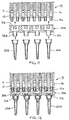
- Fig. 1 shows a vertical section of a prior-
art pipetting unit 10 with aframe part 16 containing a plurality ofdosage cylinders 12 provided withpistons 11. Thepipetting tips 20 are brought into thepipetting unit 10 as a group placed in asupport plate 21, so that all thepipetting tips 20 can be connected simultaneously to thedosage orifices 13 of thepipetting unit 10. The lower surface of theframe 16 of thepipetting unit 10 is provided with arubber seal 14 for sealing the joint between thedosage orifices 13 and thepipetting tips 20 pressed against theseal 14. - In Fig. 2, the
pipetting tips 20 placed in thesupport plate 21 have been connected to thepipetting unit 10. After this, using thepipetting tips 20 of thepipetting unit 10, liquid is drawn by suction from the sample wells of a first micro-sample plate or from separate containers and dosed into the sample wells of a second micro-sample plate or into separate containers. To draw liquid into thepipetting tip 20, thepiston 11 of thedosage cylinder 12 in theframe 16 of thepipetting unit 10 is moved upward, thus producing a negative pressure in the air space of thedosage cylinder 12. The liquid being pipetted now rises into thepipetting tip 20. Dosage is performed in reverse order by moving thepiston 11 of thedosage cylinder 12 in thepipetting unit 10 downward, causing the liquid being dosed to be correspondingly removed from thepipetting tip 20. - To allow simultaneous dosage by a plurality of
pipetting tips 20, thepipetting tips 20 in thepipetting unit 10 have to be arranged in the same way as the sample wells or separate containers used as pipetting sources. Similarly, thepipetting tips 20 have to be disposed at the same distances between them as the sample wells or separate containers used as pipetting sources. - After this, the liquid can be dosed into the sample wells or separate containers in another sample plate which have been arranged in the way as the sample wells or separate containers use as pipetting sources. The receiving sample wells also have to be disposed at the same distances between them as the sample wells or separate containers used as pipetting sources.
- However, if the
pipetting tips 20 are sufficiently narrow, then the liquid can also be dosed into the sample wells in another sample plate in which the wells are disposed at distances equalling only half the distances between the sample wells used as pipetting sources. In this case, pipetting is performed by first dosing the liquid into every second sample well in the other sample plate and then into the sample wells that were left between said every second well during the first pipetting operation. These two dosage operations have to be performed both in the widthways direction and in the lengthways direction of the sample plate, so this sample plate containing a quadruple number of sample wells can be filled via four dosage operations. - In the manner described above, using a prior-art pipetting apparatus with a pipetting unit containing 24 pipetting tips, it is possible to dose liquid from 24 sample containers or from a sample plate containing 24 sample wells into another micro-sample plate containing 24 or 96 sample wells. Similarly, using another prior-art pipetting apparatus with a pipetting unit containing 96 pipetting tips, it is possible to pipette from a micro-sample plate containing 96 sample wells into another micro-sample plate containing 96 or 384 sample wells.
- However, using prior-art apparatus, it is difficult to pipette e.g. from a sample plate containing 24 sample wells into a micro-sample plate containing 384 sample wells. This is generally due to the fact that pipetting tips designed for larger sample wells are too large to be inserted into smaller sample wells. Obviously enough, 384 sample wells accommodated in a sample plate of the same size must be considerably smaller than e.g. the sample wells in a micro-sample plate containing 96 sample wells. Therefore, it is generally likewise impossible to pipette from a micro-sample plate containing 96 sample wells into another micro-sample plate containing 1536 sample wells. It is true that pipetting can be performed using pipetting tips that are small enough to be inserted into small sample wells. In this case, however, there is the problem that the pipetting tips can only contain such a small amount of liquid that filling larger sample wells is a very slow operation. The pipetting would have to be repeated several times. Therefore, in current practice several pipetting units of different sizes are needed to enable dosage operations as described above to be carried out efficiently.
- Fig. 3 presents another prior-
art pipetting unit 10 which also usesseparate pipetting tips 20. Thepipetting tips 20 are pressed into connectingelements 15 placed opposite to thedosage cylinders 12 in theframe 16 of thepipetting unit 10. In this example, the connectingelements 15 and thepipetting tips 20 are so closely fitted that no separate seals are needed. However, there are many different ways of connecting thepipetting tips 20a, including solutions in which one or more seals, such as e.g. O-rings, are used. - The
pipetting tips 20 in Fig. 3 can be pressed into the connectingelements 15 one at a time or by using a separate pipetting tip holder, either manually or mechanically. In Fig. 4, thepipetting tips 20 have been connected to thepipetting unit 10. - Fig. 5 presents a
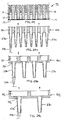
pipetting unit 10 according to the invention, which is substantially different from prior-art structures. The operation of the assembly presented in Fig. 5 does not in itself differ from the operation of previously known apparatuses, but thispipetting unit 10 forms part of a configuration the various details of which will be described in connection with the following figures. Thepipetting unit 10 in Fig. 5 comprises anadapter 30a placed between thedosage cylinders 12 in theframe 16 and thepipetting tips 20a, which adapter forms an essential part of thepipetting unit 10 of the invention. Theadapter 30a is provided withchannels 31a through which thedosage orifices 13 of the dosage cylinders 1 communicate with thepipetting tips 20. Fig. 5 shows that in this example embodiment of thepipetting unit 10 of the invention, the numbers ofdosage orifices 13 ofdosage cylinders 12,channels 31a andpipetting tips 20 are the same. - The lower surface of the
adapter 30a is provided with aseal 14b which is identical to theseal 14 on the lower surface of thepipetting unit 10. Thus, both the joint between theadapter 30a and theframe 16 of thepipetting unit 10 and the joint between the implement and thepipetting tips 20a are sealed. Fig. 5 also shows that thepipetting tips 20a and theirsupport plate 21a are identical to those in the prior-art pipetting unit 10 presented Fig. 1 and 2. In other words, known standard-type pipetting tips can be used in this embodiment of thepipetting unit 10 of the invention. Fig. 6 presents apipetting unit 10 according to the invention in an assembled state and ready for use. The inventive significance of theadapter 30a is described in connection with the following figures. - Fig. 7 presents a second embodiment of the
pipetting unit 10 of the invention in which the difference from previously known solutions can be clearly seen. The essential point is that a completelydifferent adapter 30b has been connected to apipetting unit 10frame 16 like that presented in Fig. 6. The difference betweenadapter 30b and theadapter 30a presented in Fig. 6 is that, as can be seen from the cross-sectional view in Fig. 7,channels 31b connect thedosage orifices 13 of twodosage cylinders 12 to onelarger orifice 32b, which in turn is connected to apipetting tip 20b of a conventional type. Thechannels 31b in theadapter 30b connect twodosage cylinder 12dosage orifices 13 in both widthways and lengthways directions of theadapter 30b, eachpipetting tip 20b being thus connected to fourdosage cylinder 12dosage orifices 13, as is later shown in a sectional view in Fig. 20. - Fig. 8 presents the
pipetting unit 10 of Fig. 7 in an assembled state. In the embodiments in Fig. 7 and 8, thepipetting unit 10 and itsframe 16 may be the same as in the previous figures, in other words, the apparatus is apipetting unit 10 known in itself in which only anadapter 30b according to the invention has been changed. At the same time, theadapter 30b has been fitted withlarger pipetting tips 20b, which, however, may also consist of existing, i.e. known standard-type pipetting tips 20b. The essential point about the solutions presented in Fig. 5-8 is that, by usingdifferent adapters basic part 16 of apipetting unit 10 and known pipettingtips 20b can be used in considerably more versatile ways than before. In other words, a simple solution enables a single apparatus to function like two or more prior-art apparatuses together. - Fig. 9 presents yet another variation of the solutions presented in Fig. 5-8. In this case, a
channel 31c in thethird adapter 30c according to the invention connects thedosage orifices 13 of fourdosage cylinders 12 in a cross-sectional view to alarger orifice 32c, which again is connected to apipetting tip 20c of conventional type. Here, too, it is to be noted that thechannels 31c in theadapter 30c connect fourdosage cylinder 12dosage orifices 13 in both widthways and lengthways directions of theadapter 30c, eachpipetting tip 20c being thus connected to sixteendosage cylinder 12dosage orifices 13, as is later shown in the cross-sectional view in Fig. 21. Fig. 10 presents thepipetting unit 10 of Fig. 9 in an assembled state. - In a way, the
pipetting units 10 presented in Fig. 6-10 form part of the same entity, in which the basic part of thepipetting unit 10 and theframe 16 comprised in it and containing the dosage cylinders is the same in all these figures. Thus, by only changing theadapter 30 and the associatedindividual pipetting tips 20 known in themselves, pipetting can be performed efficiently between micro-sample plates or corresponding separate containers of widely varying sizes. - As generally a single pipetting tip size is well applicable for pipetting two or three different-sized sample wells, it is possible, by alternately using apparatuses as presented in Fig. 6-10, to pipette efficiently and quickly at least 6-7 differently sized sample wells by means of three
pipetting tips 20a-20c of different sizes. In practice, this is enough to allow pipetting of all sample wells of different sizes needed in laboratory work. However, if a still wider range of application is required, then, according to the invention, the number ofadapters 30 used in thepipetting unit 10 can be increased still further. - Fig. 11 and 12 present an embodiment comprising a
pipetting unit 10 and channels 31d in anadapter 30d which in the cross-sectional view connect twodosage cylinders 12 to oneorifice 32d and further to apipetting tip 20d. As in the embodiment in Fig. 7, the channels 31d connect twodosage cylinders 12 in both widthways and lengthways directions of theadapter 30d. Eachpipetting tip 20d is thus connected to fourdosage cylinders 12. - As a difference from Fig. 7, the channels 31d in the
adapter 30d in Fig. 11 and 12 are fitted directly without separate seals to the connectingelements 15a added to theframe 16. Theorifices 32d in theadapter 30d are provided with corresponding connecting elements 15b for thepipetting tips 20d. - Fig. 13 and 14 present an embodiment in which the
adapter 30e is provided withchannels 31e which in the cross-sectional view connect fourdosage cylinders 12, i.e. in the widthways and lengthways directions a total of sixteendosage cylinders 12 to oneorifice 32e and further to apipetting tip 20e of a known type. In this embodiment, too, theadapter 30e can be connected via the orifices of thechannels 31e to the connectingelements 15a of theframe 16 of thepipetting unit 10 without separate seals. Similarly, aconventional pipetting tip 20e can be connected to the connectingelement 15e of theadapter 30e without separate seals. A sectional view of thisadapter 30e is presented in Fig. 22. - The solutions presented in Fig. 10-14 are also in a way part of the same entity in which
different adapters 30 andpipetting tips 20, conventional in themselves but of different sizes, connected to them can be used in connection with the basic part of thepipetting unit 10 and itsframe 16. In this way, a very wide range of use of the same multichannel pipetting apparatus is achieved in the pipetting of sample wells of different sizes. - Fig. 15 and 16 present an embodiment of a
pipetting unit 10 in which the upper surface of theadapter 30f is provided with aseal 14f. In this case, theadapter 30f can be fitted tightly against thelower surface 17 of theframe 16 of thepipetting unit 10 as an alternative to connection to connectingelements 15a, which was the case in the previous example. In this example, one largecommon channel 31f connects fouradjacent dosage cylinders 12 arranged in a quadratic array to asingle orifice 32f. - The
adapter 30f can also be varied in numerous other ways by combining different types of joint at its upper and lower surfaces. The drawings and this description do not present all these alternatives. For example, the lower surface ofadapter 30f may be straight as in Fig. 7 and provided with aseal 14 instead of connectingelements 15f. In this case, in place ofpipetting tips 20d, there will be standard-type pipetting tips 20b together with a support plate 21b, as in Fig. 7. - Fig. 17 and 18 present a solution resembling the one presented in Fig. 15 and 16, likewise with a seal 14g on the upper surface of the
adapter 30g. The difference in this example is that, instead of connecting fourdosage cylinders 12 of theframe 16 of thepipetting unit 10, one largecommon channel 31g connects sixteendosage cylinders 12 to anorifice 32e in theadapter 30g and further to apipetting tip 20e of a known type. - Fig. 19-22 present horizontal sections through certain
alternative adapters adapter 30a in Fig. 19, eachchannel 31a connects only one dosage cylinder directly to one pipetting tip, as shown in Fig. 5 and 6. - In the
adapter 30b in Fig. 20, eachchannel 31b connects fourdosage cylinders 12 in theframe 16 of thepipetting unit 10 to oneorifice 32b in theadapter 30b and further to apipetting tip 20e of a known type as shown in Fig. 7 and 8. - In the
adapter 30c in Fig. 21, a largecommon channel 31c connects sixteen dosage cylinders of thepipetting unit 10, arranged in a quadratic array, to oneorifice 32c and further to a pipetting tip of a known type. A vertical section of a corresponding pipetting unit is presented in Fig. 9 and 10. - The
adapter 30e in Fig. 22 contains severalsmall channels 31e which also connect sixteen dosage cylinders of thepipetting unit 10 to oneorifice 32e and further to a pipetting tip of a known type as in the previous figure. However, there is a difference in the structure of the channel system, in which, instead of a single large space, several small channels are connected to theorifice 32e. A vertical section of apipetting unit 10 corresponding to this embodiment is shown in Fig. 13 and 14. - Fig. 23 presents a
pipetting unit 10 with anadapter 30b like that in Fig. 7 and 8. However, theframe 16 of thepipetting unit 10 differs in that the dosage cylinders are located at a distance from theadapter 30b. The dosage cylinders, which are not shown in Fig. 23, are connected viatubes 18 to thedosage orifices 13 of theframe 16. - Fig. 24 presents a
pipetting unit 10 to whoseframe 16 it is possible to alternatively connect one of threedifferent adapters 30 provided with fixedpipetting tips 23 or withseparate pipetting tips 20a placed over them. Theadapter 30h in Fig. 24a has one fixed pipetting tip for eachdosage cylinder 12 of thepipetting unit 10. The adapter 30i in Fig. 24b again has one fixed pipetting tip 231 or aseparate pipetting tip 20b placed over it for fourdosage cylinders 12 of thepipetting unit 10. Theadapter 30j in Fig. 24c again has one fixed pipetting tip 23j or aseparate pipetting tip 20c placed over it for sixteendosage cylinders 12 of thepipetting unit 10. In the embodiments presented in Fig. 24, fixedpipetting tips 23 can be used e.g. when the apparatus is mainly used for only dosing a liquid. To transfer a liquid from a sample plate to another by pipetting, it is generally necessary to use replaceableseparate tips 20. - Fig. 25 presents a
pipetting unit 10 in which theframe 16 is connected to a laterallymovable adapter 30k provided with different fixedpipetting tips 23 or withseparate pipetting tips 20 placed over them. Theadapter 30k can be moved laterally so that eitherzone adapter 30k comes to the position directly opposite to thedosage orifices 13 of the dosage cylinders. - In
zone 22a of theadapter 30k, each dosagecylinder dosage orifice 13 is aligned with achannel 31h which leads to a fixed pipetting tip 23a or aseparate pipetting tip 20a placed over it, likewise aligned with the orifice.
Inzone 22b of theadapter 30k, there is a connectingchannel 31 i, an orifice 32i and a fixedpipetting tip 23b or aseparate pipetting tip 20b placed over it for fourdosage cylinders 12 of thepipetting unit 10.Zone 22c of theadapter 30k again has a connectingchannel 31j, anorifice 32j and a fixedpipetting tip 23c or aseparate pipetting tip 20c placed over it for sixteendosage cylinders 12 of thepipetting unit 10. - The pipetting process can be varied depending on the type of micro-sample plate under pipetting simply by moving one of the
zones adapter 30k to the position directly opposite to thedosage orifices 13 of the dosage cylinders of thepipetting unit 10. As described above, the pipetting tips in this embodiment are fixedly joined to theadapter 30k. Alternatively, it is naturally also possible to use separate, preferably standard-type pipetting tips either in addition to the fixedpipetting tips 23, e.g. by placing them over these, or instead of these. Whenseparate pipetting tips 20 are used, the apparatus can also be so implemented that either the measuring head of thepipetting unit 10 or themovable adapter 30k fetches new pipetting tips when necessary. - Using the
pipetting unit 10 in Fig. 25, the pipetting of the sample wells of a sample plate can be carried out by selecting from theadapter 30k pipetting tips - Fig. 26 presents a diagrammatic top view of a
pipetting apparatus 40 according to the invention. Thepipetting apparatus 40 comprises apipetting unit 10 and atrack 41 for feeding and movingmicro-sample plates 42 in lateral directions to bring them to a position directly opposite to thepipetting unit 10. Thepipetting unit 10 also comprises anadapter 30 which can be moved laterally but also perpendicularly to the movement of thetrack 41 and which contains severalpipetting tip groups 22 consisting of pipetting tips of different sizes. Theadapter 30 is moved laterally so as to bring a desiredpipetting tip group 22 to the active position directly opposite to thepipetting unit 10. Thepipetting tip group 22 is selected by the type of themicro-sample plate 42 brought on thetrack 41 to the position opposite to thepipetting unit 10 and by the number ofsample wells 44 in the sample plate. - As the
track 41 of themicro-sample plates 42 and the movements of theadapter 30 of thepipetting unit 10 are independent from each other, these movements can be controlled so as to bring any one of the pipetting tip groups and micro-sample plates to thepipetting unit 10 for pipetting. In other words, all possible combinations are feasible. The essential point about the apparatus is not whether the pipetting tips are fixedly or detachably mounted in theadapter 30. In practice, naturally the most advantageous alternative is to use separate standard-type pipetting tips. In the apparatus in Fig. 26, it is also possible to use an arrangement whereby the apparatus also fetches new pipetting tips into theadapter 30 as necessary. - Fig. 27 presents the
pipetting apparatus 40 of Fig. 26 in side view. The figure shows apipetting unit 10 and anadapter 30 and below them atrack 41 for feeding and movingmicro-sample plates 42 laterally to the position opposite to thepipetting unit 10. Theadapter 30 moves in a direction perpendicular to the movement of thetrack 41, i.e. in a direction away from the plane of the drawing. - Fig. 28 presents a
pipetting apparatus 40 which is a simplified version of the apparatus presented in Fig. 26 and 27, and in which themicro-sample plates 42 are fed onto thetrack 41 from afeed device 43. Thepipetting unit 10 above thetrack 41 is provided with amovable adapter 30 with three replaceable pipetting tip groups 22. Thepipetting unit 10 can fetch a new group to replace apipetting tip group 22 when necessary. The pipetting tips may be fixed or separate tips. - Fig. 29 presents a more detailed view of a
replaceable adapter 30a containing 384channels 31a. It is intended for pipetting a known micro-sample plate containing 384 sample wells, in which the sample wells are arranged in the same order as thechannels 31a in theadapter 30a. The dosage cylinders above theadapter 30a are also spaced at the same distances between them as thechannels 31a of theadapter 30a and the pipetting tips and sample wells of the micro-sample plate below them. Thus, each dosage cylinder is connected via onechannel 31a of theadapter 30a to one pipetting tip aligned with the sample well. - Fig. 30 also shows a more detailed view of another
replaceable adapter 30b of thepipetting unit 10, containing 96 connectingchannels 31b of another type. If theadapter 30a in the pipetting unit in Fig. 29 is replaced with thisadapter 31b, then each connectingchannel 31b connects four dosage cylinders of the pipetting unit via an orifice 32 to one larger, standard-type pipetting tip. In this case, the distance between these larger pipetting tips corresponds to the distance between the sample wells of a micro-sample plate containing 96 sample wells. - Fig. 31 shows in a diagrammatic form how a
replaceable adapter 30b of thepipetting unit 10 as presented in Fig. 30 connects four dosage cylinder dosage orifices to onedosage orifice 32b in theadapter 30, which again can be connected to a standard-type pipetting tip. In each group of four dosage orifices, theorifice 32b to the pipetting tip is placed in the middle of the group. By means of thisadapter 30b, using a pipetting unit containing 384 dosage cylinders, a micro-sample plate containing 96 sample wells can be pipetted. Again, by replacing the adapter in the pipetting unit with anadapter 30a as presented in Fig. 29, a micro-sample plate containing 384 sample wells can be pipetted. - Fig. 32 presents an example of the laterally
movable adapter 30 of thepipetting unit 10. Thisadapter 30 comprises twozones first zone 22a contains onlydirect channels 31a while thesecond zone 22b contains onlychannels 31b connecting four dosage cylinder dosage orifices to oneorifice 32b. Theadapter 30 in Fig. 32 may alternatively be formed by disposing thezones adapter 30 may also comprise any number ofzones 22 combined in any order. - Fig. 33 presents as an example a lateral view of a
pipetting unit 10 provided with a laterallymovable adapter 30 as shown in Fig. 32. In Fig. 33, theadapter 30 is in a position such that the dosage orifices of thedosage cylinders 12 are aligned with thedirect channels 31a. - In Fig. 34 again, the laterally
movable adapter 30 of thepipetting unit 10 is in a position such that the dosage orifices of thedosage cylinders 12 are aligned with thechannels 31b connecting four dosage cylinder dosage orifices. - It is obvious to the person skilled in the art that different embodiments of the invention may be varied within the scope of the claims presented below.
Claims (12)
- Pipetting method for simultaneous pipetting of a plurality of sample wells (44) or containers by means of a multichannel pipetting apparatus (40) comprising a pipetting unit (10) provided with a plurality of pipetting channels (12), according to which methodcharacterised in thatthe pipetting channels (12) of the multichannel pipetting unit (10) are divided into groups, at least some of which comprise two or more pipetting channels, andthe pipetting tips (20) of the pipetting unit (10) are so connected to the groups of pipetting channels (12) that each pipetting tip communicates with all the pipetting channels of one group,the groups of two or more pipetting channels (12) of the pipetting unit (10) are connected to the pipetting tips (20) by bringing between the pipetting channels and the pipetting tips an adapter (30) containing several channels (31),by means of the adapter (30), each one of two or more groups of pipetting channels (12) is connected to a separate pipetting tip (20) via a channel (31) or channel group in the adapter (30) that is in alignment with the group,and that the channel (31) or channel group in the adapter (30) is connected to the pipetting tip (20), which preferably is a conventional, funnel-shaped pipetting tip.
- Pipetting method as defined in claim 1, characterised in thatthe adapter between the pipetting channels (12) and the pipetting tips (20) is replaced with a different adapter (30) depending on the number of pipetting channels comprised in the group to be connected to each pipetting tip.
- Pipetting method as defined in claim 1, characterised in thatthe adapter (30) placed between the pipetting channels (12) and the pipetting tips (20) is moved in lateral direction so that the desired channel (31) or channel group is brought to a position directly opposite to the selected pipetting channels, said selection being made according to the number of pipetting channels comprised in the group to be connected to each pipetting tip.
- Pipetting method as defined in claim 1, characterised in thatby means of the adapter (30) movable in the pipetting apparatus (40), the pipetting tips (20) to be connected to the adapter are fetched according to the size of the sample wells (44) or containers to be pipetted, whereupon the adapter is moved laterally so that the channel (31) or channel group in the adapter which is in alignment with the pipetting tip comes to a position directly opposite to the desired group of pipetting channels, this selection being made according to the number of pipetting channels comprised in the group to be connected to each pipetting tip.
- Multichannel pipetting apparatus (40) for simultaneous pipetting of a plurality of sample wells (44) or containers, said pipetting apparatus comprisingcharacterized in thata pipetting unit (10) comprising a number of pipetting channels (12),in which pipetting apparatus the pipetting channels (12) have been divided into groups, at least some of which comprise two or more pipetting channels,and the pipetting tips (20) of the pipetting unit (10) are connected to the groups of pipetting channels (12) so that each pipetting tip communicates with all the pipetting channels in one group,the pipetting unit (10) of the pipetting apparatus (40) comprises at least one adapter (30) placed between the pipetting channels (12) and the pipetting tips (20) and containing a number of channels (31) or channel groups connecting the groups of pipetting channels to the pipetting tips,and that each channel (31) or channel group in the adapter (30) is connected to one group of pipetting channels (12) and via an orifice (32) to one pipetting tip (20), which preferably is a conventional, funnel-shaped pipetting tip.
- Pipetting apparatus (40) as defined in claim 5, characterised in thatthe pipetting unit (10) comprises at least two different adapters (30) which can be alternately placed in the pipetting unit, between the pipetting channels (12) and the pipetting tips (20),the adapters (30) contain different channels (31) or channel groups,that the channels (31) or channel groups in different adapters (30) differ from each other in that a different number of pipetting channels (12) can be connected via them to each pipetting tip (20).
- Pipetting apparatus (40) as defined in claim 5, characterised in thatthe pipetting unit (10) comprises an adapter (30) comprising at least two different zones (22) containing different channels (31) or channel groups,the channels (31) or channel groups located in different zones (22) of the adapter (30) differ from each other in that a different number of pipetting channels (12) can be connected via them to each pipetting tip (20), and thatthe adapter (30) can be displaced or moved so as to bring different zones (22) alternately into connection with the pipetting channels (12).
- Pipetting apparatus (40) as defined in claim 5, 6 or 7, characterised in thatthe pipetting apparatus (40) comprises a track (41) for moving micro-sample plates (42) laterally to a position directly opposite to the pipetting unit (10),the pipetting unit (10) contains one or more adapters (30) which can be moved above the track (41) in a direction perpendicular to the direction of movement of the track, and thatone or more adapters contain two or more different zones (22) containing channels (31) or channel groups which connect a different number of pipetting channels (12) to each pipetting tip (20).
- Pipetting apparatus (40) as defined in any one of claims 5-8, characterised in that, using one or more adapters (30), the pipetting apparatus (40) forms an apparatus that replaces at least two previously known pipetting apparatuses.
- Pipetting apparatus (40) as defined in any one of claims 5-9, characterised in that the adapter (30) is provided with a plurality of pipetting tips (20) or pipetting tip connecting elements (15) fixedly attached to it.
- Pipetting apparatus (40) as defined in any one of claims 5-10,
characterised in that the channels (31) or channel groups of the adapter (30) are fitted against a seal (14a) on the lower surface (17) of the frame (16) of the pipetting unit (10) or against suitable connecting elements (15). - Pipetting apparatus (40) as defined in any one of claims 5-11,
characterised in that the pipetting tips (20) are fitted against a seal (14b) on the lower surface of the adapter (30) or against suitable connecting elements (15).
Applications Claiming Priority (2)
| Application Number | Priority Date | Filing Date | Title |
|---|---|---|---|
| FI20002761A FI20002761A0 (en) | 2000-12-15 | 2000-12-15 | Multi-channel pipette device |
| FI20002761 | 2000-12-15 |
Publications (3)
| Publication Number | Publication Date |
|---|---|
| EP1214977A2 true EP1214977A2 (en) | 2002-06-19 |
| EP1214977A3 EP1214977A3 (en) | 2003-10-15 |
| EP1214977B1 EP1214977B1 (en) | 2009-10-07 |
Family
ID=8559730
Family Applications (1)
| Application Number | Title | Priority Date | Filing Date |
|---|---|---|---|
| EP01660233A Expired - Lifetime EP1214977B1 (en) | 2000-12-15 | 2001-12-17 | Pipetting method and multichannel pipetting apparatus |
Country Status (6)
| Country | Link |
|---|---|
| US (1) | US6841130B2 (en) |
| EP (1) | EP1214977B1 (en) |
| AT (1) | ATE444810T1 (en) |
| DE (1) | DE60140108D1 (en) |
| ES (1) | ES2334432T3 (en) |
| FI (1) | FI20002761A0 (en) |
Cited By (4)
| Publication number | Priority date | Publication date | Assignee | Title |
|---|---|---|---|---|
| US7219567B2 (en) * | 2005-01-05 | 2007-05-22 | Bio-Magnetics Ltd. | Combinatorial pipettor device |
| EP2006021A1 (en) * | 2007-06-21 | 2008-12-24 | Hamilton Bonaduz AG | Pipette tip |
| ITRE20130097A1 (en) * | 2013-12-27 | 2015-06-28 | Spire S R L | MACHINE AND A METHOD OF INSEMINATION OF DIAGNOSTIC PLATES |
| EP3834943A1 (en) | 2019-12-11 | 2021-06-16 | Tecan Trading Ag | Combinable cavity tray, assembly of combinable cavity trays, method of manufacturing and use of a combinable cavity tray |
Families Citing this family (25)
| Publication number | Priority date | Publication date | Assignee | Title |
|---|---|---|---|---|
| US20010036425A1 (en) * | 1995-10-12 | 2001-11-01 | Michel Gazeau | Device for transferring samples of micro-amounts of liquids |
| GB9906477D0 (en) * | 1999-03-19 | 1999-05-12 | Pyrosequencing Ab | Liquid dispensing apparatus |
| DE19917375C2 (en) * | 1999-04-16 | 2001-09-27 | Hamilton Bonaduz Ag Bonaduz | Pipetting unit |
| DE10013511A1 (en) * | 2000-03-20 | 2001-10-11 | Brand Gmbh & Co Kg | Multiple channel pipetting arrangement used for microtitration plates has pipette shafts each having a sealing receiver on the upper end with a plunger seal arranged in it |
| US7335337B1 (en) * | 2001-09-11 | 2008-02-26 | Smith James C | Ergonomic pipette tip and adapters |
| US20040141885A1 (en) * | 2002-02-12 | 2004-07-22 | Molecular Devices Corp. | Pipettor systems and components |
| DE10238266A1 (en) * | 2002-02-28 | 2003-11-06 | Ibidi Gmbh | Microfluidic system |
| JP3648487B2 (en) * | 2002-03-01 | 2005-05-18 | アロカ株式会社 | Nozzle tip for dispensing equipment |
| US20040071602A1 (en) * | 2002-10-15 | 2004-04-15 | Yiu Felix H. | Pipettor head adapter |
| US20050069949A1 (en) * | 2003-09-30 | 2005-03-31 | International Business Machines Corporation | Microfabricated Fluidic Structures |
| US20050069462A1 (en) * | 2003-09-30 | 2005-03-31 | International Business Machines Corporation | Microfluidics Packaging |
| US7919047B2 (en) * | 2006-03-03 | 2011-04-05 | Vertex Pharmaceuticals Incorporated | Air displacement pipetter |
| DE102007005323A1 (en) * | 2007-01-29 | 2008-07-31 | Bioplan Consulting Gmbh | Suction device has multiple suction needles and vacuum chamber, in which suction needles empty and connection is provided for vacuum source |
| US8117925B2 (en) * | 2007-07-06 | 2012-02-21 | Yiu Felix H | Apparatus and method for using a tip collar on pipette tips providing structural rigidity |
| US8759113B2 (en) * | 2008-10-31 | 2014-06-24 | Fraunhofer-Gesellschaft zur Förderung der angewandten Forschung e.V. | Device for receiving a liquid and also device for applying liquids on sample carriers and method for this purpose |
| DE202010003532U1 (en) | 2010-03-11 | 2010-07-01 | Cybio Ag | Pipetting unit and pipettor, comprising such a pipette unit, and pipette tip for use with such a pipettor |
| US11559802B2 (en) | 2011-07-20 | 2023-01-24 | Avidien Technologies, Inc. | Pipette tip adapter |
| EP2734301B1 (en) * | 2011-07-20 | 2019-02-20 | Avidien Technologies | Pipette tip adapter |
| DE102011053808A1 (en) | 2011-09-20 | 2013-03-21 | Cybio Ag | Pipetting head with groups of Pipetierkanälen different diameters and device with such a pipetting head |
| US9352312B2 (en) * | 2011-09-23 | 2016-05-31 | Alere Switzerland Gmbh | System and apparatus for reactions |
| US9791080B2 (en) | 2012-03-12 | 2017-10-17 | Idex Health & Science Llc | Microfluidic interconnect |
| CH708139A2 (en) * | 2013-06-06 | 2014-12-15 | Tecan Trading Ag | Pipetting. |
| US9927452B2 (en) | 2014-08-20 | 2018-03-27 | Rai Strategic Holdings, Inc. | Pipetting system |
| US10821434B2 (en) | 2014-11-18 | 2020-11-03 | Avidien Technologies, Inc. | Multichannel air displacement pipettor |
| USD905267S1 (en) | 2019-03-27 | 2020-12-15 | Avidien Technologies, Inc. | Pipette tip adapter |
Citations (4)
| Publication number | Priority date | Publication date | Assignee | Title |
|---|---|---|---|---|
| DE19712195A1 (en) * | 1997-03-22 | 1998-09-24 | Univ Schiller Jena | Off line sample analysis |
| US5970806A (en) * | 1996-11-13 | 1999-10-26 | Labsystems Oy | Multi-cylinder pipette |
| WO2000047249A1 (en) * | 1999-02-10 | 2000-08-17 | Robbins Scientific Corporation | Syringe array with adjustable needle spacing |
| EP1074302A2 (en) * | 1999-08-03 | 2001-02-07 | Michael Theran | Multichannel pipette system and pipette tips therefor |
Family Cites Families (11)
| Publication number | Priority date | Publication date | Assignee | Title |
|---|---|---|---|---|
| US4237095A (en) * | 1978-04-25 | 1980-12-02 | Kommandiittiyhtio Finnpipette Osmo A. Suovaniemi | Tip vessel for use in connection with a dosage pipette |
| US4824642A (en) * | 1986-10-21 | 1989-04-25 | Costar Corporation | Multi-channel pipetter |
| US4779467A (en) * | 1987-01-28 | 1988-10-25 | Rainin Instrument Co., Inc. | Liquid-end assembly for multichannel air-displacement pipette |
| US5827745A (en) * | 1993-03-29 | 1998-10-27 | Astle; Thomas W. | Micropipette tip loading and unloading device and method and tip package |
| US5497670A (en) * | 1995-03-31 | 1996-03-12 | Carl; Richard A. | Liquid dispensing apparatus including means for loading pipette tips onto liquid dispensing cylinders and maintaining the loading force during the apparatus operation cycle |
| WO1999013987A1 (en) * | 1997-09-16 | 1999-03-25 | Life Technologies, Inc. | Gel loading adapter |
| US6451263B1 (en) * | 1999-11-04 | 2002-09-17 | Helena Laboratories Corporation | Pipette adapter |
| DE10013511A1 (en) * | 2000-03-20 | 2001-10-11 | Brand Gmbh & Co Kg | Multiple channel pipetting arrangement used for microtitration plates has pipette shafts each having a sealing receiver on the upper end with a plunger seal arranged in it |
| DE10022693C1 (en) * | 2000-05-05 | 2001-10-11 | Cybio Instr Gmbh | Automatic pipetting system for filling microtiter plates has single row, multichannel head with mechanism for stripping nozzles from pipettes |
| DE10043345C2 (en) * | 2000-08-24 | 2003-01-09 | Cybio Instr Gmbh | Device for fully automatic solid phase extraction |
| US20040071602A1 (en) * | 2002-10-15 | 2004-04-15 | Yiu Felix H. | Pipettor head adapter |
-
2000
- 2000-12-15 FI FI20002761A patent/FI20002761A0/en unknown
-
2001
- 2001-12-17 ES ES01660233T patent/ES2334432T3/en not_active Expired - Lifetime
- 2001-12-17 EP EP01660233A patent/EP1214977B1/en not_active Expired - Lifetime
- 2001-12-17 AT AT01660233T patent/ATE444810T1/en active
- 2001-12-17 US US10/016,680 patent/US6841130B2/en not_active Expired - Lifetime
- 2001-12-17 DE DE60140108T patent/DE60140108D1/en not_active Expired - Lifetime
Patent Citations (4)
| Publication number | Priority date | Publication date | Assignee | Title |
|---|---|---|---|---|
| US5970806A (en) * | 1996-11-13 | 1999-10-26 | Labsystems Oy | Multi-cylinder pipette |
| DE19712195A1 (en) * | 1997-03-22 | 1998-09-24 | Univ Schiller Jena | Off line sample analysis |
| WO2000047249A1 (en) * | 1999-02-10 | 2000-08-17 | Robbins Scientific Corporation | Syringe array with adjustable needle spacing |
| EP1074302A2 (en) * | 1999-08-03 | 2001-02-07 | Michael Theran | Multichannel pipette system and pipette tips therefor |
Cited By (5)
| Publication number | Priority date | Publication date | Assignee | Title |
|---|---|---|---|---|
| US7219567B2 (en) * | 2005-01-05 | 2007-05-22 | Bio-Magnetics Ltd. | Combinatorial pipettor device |
| EP2006021A1 (en) * | 2007-06-21 | 2008-12-24 | Hamilton Bonaduz AG | Pipette tip |
| ITRE20130097A1 (en) * | 2013-12-27 | 2015-06-28 | Spire S R L | MACHINE AND A METHOD OF INSEMINATION OF DIAGNOSTIC PLATES |
| EP3834943A1 (en) | 2019-12-11 | 2021-06-16 | Tecan Trading Ag | Combinable cavity tray, assembly of combinable cavity trays, method of manufacturing and use of a combinable cavity tray |
| US11925936B2 (en) | 2019-12-11 | 2024-03-12 | Tecan Trading Ag | Combinable cavity tray, assembly of combinable cavity trays, method of manufacturing and use of a combinable cavity tray |
Also Published As
| Publication number | Publication date |
|---|---|
| EP1214977B1 (en) | 2009-10-07 |
| ES2334432T3 (en) | 2010-03-10 |
| US20020086440A1 (en) | 2002-07-04 |
| ATE444810T1 (en) | 2009-10-15 |
| US6841130B2 (en) | 2005-01-11 |
| EP1214977A3 (en) | 2003-10-15 |
| FI20002761A0 (en) | 2000-12-15 |
| DE60140108D1 (en) | 2009-11-19 |
Similar Documents
| Publication | Publication Date | Title |
|---|---|---|
| EP1214977A2 (en) | Pipetting method and multichannel pipetting apparatus | |
| AU753307B2 (en) | Capillary electroflow apparatus and method | |
| US6103199A (en) | Capillary electroflow apparatus and method | |
| US7185551B2 (en) | Pipetting module | |
| AU781327B2 (en) | Method and apparatus for dispensing a liquid into a series of wells | |
| US6284113B1 (en) | Apparatus and method for transferring liquids | |
| Wölcke et al. | Miniaturized HTS technologies–uHTS | |
| US20130068041A1 (en) | Pipetting apparatus with a pipetting head comprising a multiplicity of pipetting channels disposed in an arrangement pattern | |
| DE60013983T2 (en) | Multi-channel pipette system and pipette tips for it | |
| CN101368206B (en) | Sequencing reaction small chamber, gene sequencing reaction bench and gene sequencing device | |
| CN104755938A (en) | Dispensing tip with built-in deforming element, dispensing device with built-in deforming element and processing method using built-in deforming element dispensing | |
| WO2000044497A1 (en) | Pipetter | |
| JPH10156196A (en) | Multicylinder pipette | |
| WO2003062815A1 (en) | Multi-segment cartridge for bio-separation with multiplexed fluorescence detection | |
| CN110520719A (en) | Disposable multichannel bio-analysis cartridge and the capillary electrophoresis system for bioanalysis using it | |
| US20080003147A1 (en) | Fluid handling system for flow-through assay | |
| JP3423187B2 (en) | Dispensing device | |
| KR102227970B1 (en) | Device for generating fine droplets | |
| US20050032241A1 (en) | Reagent dispenser and dispensing method | |
| CN112657567A (en) | Device for filling pipette tips | |
| CN211284377U (en) | Counting board upper cover plate and cell counting board | |
| KR20030008339A (en) | Lab on a chip system connected by capillaries | |
| ITFI970179A1 (en) | WAREHOUSE FOR REAGENTS BOTTLES IN A LABORATORY ANALYSIS EQUIPMENT OR SIMILAR, AND EQUIPMENT CONTAINING SAID WAREHOUSE |
Legal Events
| Date | Code | Title | Description |
|---|---|---|---|
| PUAI | Public reference made under article 153(3) epc to a published international application that has entered the european phase |
Free format text: ORIGINAL CODE: 0009012 |
|
| AK | Designated contracting states |
Kind code of ref document: A2 Designated state(s): AT BE CH CY DE DK ES FI FR GB GR IE IT LI LU MC NL PT SE TR |
|
| AX | Request for extension of the european patent |
Free format text: AL;LT;LV;MK;RO;SI |
|
| PUAL | Search report despatched |
Free format text: ORIGINAL CODE: 0009013 |
|
| AK | Designated contracting states |
Kind code of ref document: A3 Designated state(s): AT BE CH CY DE DK ES FI FR GB GR IE IT LI LU MC NL PT SE TR |
|
| AX | Request for extension of the european patent |
Extension state: AL LT LV MK RO SI |
|
| 17P | Request for examination filed |
Effective date: 20040415 |
|
| AKX | Designation fees paid |
Designated state(s): AT BE CH CY DE DK ES FI FR GB GR IE IT LI LU MC NL PT SE TR |
|
| 17Q | First examination report despatched |
Effective date: 20080125 |
|
| GRAP | Despatch of communication of intention to grant a patent |
Free format text: ORIGINAL CODE: EPIDOSNIGR1 |
|
| GRAS | Grant fee paid |
Free format text: ORIGINAL CODE: EPIDOSNIGR3 |
|
| GRAA | (expected) grant |
Free format text: ORIGINAL CODE: 0009210 |
|
| RIN1 | Information on inventor provided before grant (corrected) |
Inventor name: SUONTAUSTA, JARI Inventor name: LEHTINEN, KAUKO |
|
| AK | Designated contracting states |
Kind code of ref document: B1 Designated state(s): AT BE CH CY DE DK ES FI FR GB GR IE IT LI LU MC NL PT SE TR |
|
| REG | Reference to a national code |
Ref country code: GB Ref legal event code: FG4D |
|
| REG | Reference to a national code |
Ref country code: CH Ref legal event code: EP |
|
| REG | Reference to a national code |
Ref country code: IE Ref legal event code: FG4D |
|
| REF | Corresponds to: |
Ref document number: 60140108 Country of ref document: DE Date of ref document: 20091119 Kind code of ref document: P |
|
| REG | Reference to a national code |
Ref country code: SE Ref legal event code: TRGR |
|
| REG | Reference to a national code |
Ref country code: CH Ref legal event code: NV Representative=s name: HEPP WENGER RYFFEL AG |
|
| NLV1 | Nl: lapsed or annulled due to failure to fulfill the requirements of art. 29p and 29m of the patents act | ||
| REG | Reference to a national code |
Ref country code: ES Ref legal event code: FG2A Ref document number: 2334432 Country of ref document: ES Kind code of ref document: T3 |
|
| PG25 | Lapsed in a contracting state [announced via postgrant information from national office to epo] |
Ref country code: PT Free format text: LAPSE BECAUSE OF FAILURE TO SUBMIT A TRANSLATION OF THE DESCRIPTION OR TO PAY THE FEE WITHIN THE PRESCRIBED TIME-LIMIT Effective date: 20100208 Ref country code: FI Free format text: LAPSE BECAUSE OF FAILURE TO SUBMIT A TRANSLATION OF THE DESCRIPTION OR TO PAY THE FEE WITHIN THE PRESCRIBED TIME-LIMIT Effective date: 20091007 |
|
| PG25 | Lapsed in a contracting state [announced via postgrant information from national office to epo] |
Ref country code: BE Free format text: LAPSE BECAUSE OF FAILURE TO SUBMIT A TRANSLATION OF THE DESCRIPTION OR TO PAY THE FEE WITHIN THE PRESCRIBED TIME-LIMIT Effective date: 20091007 |
|
| PG25 | Lapsed in a contracting state [announced via postgrant information from national office to epo] |
Ref country code: DK Free format text: LAPSE BECAUSE OF FAILURE TO SUBMIT A TRANSLATION OF THE DESCRIPTION OR TO PAY THE FEE WITHIN THE PRESCRIBED TIME-LIMIT Effective date: 20091007 Ref country code: MC Free format text: LAPSE BECAUSE OF NON-PAYMENT OF DUE FEES Effective date: 20100701 Ref country code: NL Free format text: LAPSE BECAUSE OF FAILURE TO SUBMIT A TRANSLATION OF THE DESCRIPTION OR TO PAY THE FEE WITHIN THE PRESCRIBED TIME-LIMIT Effective date: 20091007 |
|
| PLBE | No opposition filed within time limit |
Free format text: ORIGINAL CODE: 0009261 |
|
| STAA | Information on the status of an ep patent application or granted ep patent |
Free format text: STATUS: NO OPPOSITION FILED WITHIN TIME LIMIT |
|
| 26N | No opposition filed |
Effective date: 20100708 |
|
| PG25 | Lapsed in a contracting state [announced via postgrant information from national office to epo] |
Ref country code: IE Free format text: LAPSE BECAUSE OF NON-PAYMENT OF DUE FEES Effective date: 20091217 Ref country code: GR Free format text: LAPSE BECAUSE OF FAILURE TO SUBMIT A TRANSLATION OF THE DESCRIPTION OR TO PAY THE FEE WITHIN THE PRESCRIBED TIME-LIMIT Effective date: 20100108 |
|
| PG25 | Lapsed in a contracting state [announced via postgrant information from national office to epo] |
Ref country code: IT Free format text: LAPSE BECAUSE OF FAILURE TO SUBMIT A TRANSLATION OF THE DESCRIPTION OR TO PAY THE FEE WITHIN THE PRESCRIBED TIME-LIMIT Effective date: 20091007 |
|
| PG25 | Lapsed in a contracting state [announced via postgrant information from national office to epo] |
Ref country code: LU Free format text: LAPSE BECAUSE OF NON-PAYMENT OF DUE FEES Effective date: 20091217 |
|
| PG25 | Lapsed in a contracting state [announced via postgrant information from national office to epo] |
Ref country code: TR Free format text: LAPSE BECAUSE OF FAILURE TO SUBMIT A TRANSLATION OF THE DESCRIPTION OR TO PAY THE FEE WITHIN THE PRESCRIBED TIME-LIMIT Effective date: 20091007 |
|
| PG25 | Lapsed in a contracting state [announced via postgrant information from national office to epo] |
Ref country code: CY Free format text: LAPSE BECAUSE OF FAILURE TO SUBMIT A TRANSLATION OF THE DESCRIPTION OR TO PAY THE FEE WITHIN THE PRESCRIBED TIME-LIMIT Effective date: 20091007 |
|
| REG | Reference to a national code |
Ref country code: FR Ref legal event code: PLFP Year of fee payment: 15 |
|
| REG | Reference to a national code |
Ref country code: FR Ref legal event code: PLFP Year of fee payment: 16 |
|
| REG | Reference to a national code |
Ref country code: FR Ref legal event code: PLFP Year of fee payment: 17 |
|
| PGFP | Annual fee paid to national office [announced via postgrant information from national office to epo] |
Ref country code: CH Payment date: 20201215 Year of fee payment: 20 Ref country code: SE Payment date: 20201211 Year of fee payment: 20 Ref country code: DE Payment date: 20201201 Year of fee payment: 20 Ref country code: GB Payment date: 20201209 Year of fee payment: 20 Ref country code: FR Payment date: 20201112 Year of fee payment: 20 Ref country code: AT Payment date: 20201125 Year of fee payment: 20 |
|
| PGFP | Annual fee paid to national office [announced via postgrant information from national office to epo] |
Ref country code: ES Payment date: 20210108 Year of fee payment: 20 |
|
| REG | Reference to a national code |
Ref country code: DE Ref legal event code: R071 Ref document number: 60140108 Country of ref document: DE |
|
| REG | Reference to a national code |
Ref country code: CH Ref legal event code: PL |
|
| REG | Reference to a national code |
Ref country code: GB Ref legal event code: PE20 Expiry date: 20211216 |
|
| REG | Reference to a national code |
Ref country code: SE Ref legal event code: EUG |
|
| PG25 | Lapsed in a contracting state [announced via postgrant information from national office to epo] |
Ref country code: GB Free format text: LAPSE BECAUSE OF EXPIRATION OF PROTECTION Effective date: 20211216 |
|
| REG | Reference to a national code |
Ref country code: AT Ref legal event code: MK07 Ref document number: 444810 Country of ref document: AT Kind code of ref document: T Effective date: 20211217 |
|
| REG | Reference to a national code |
Ref country code: ES Ref legal event code: FD2A Effective date: 20220405 |
|
| PG25 | Lapsed in a contracting state [announced via postgrant information from national office to epo] |
Ref country code: ES Free format text: LAPSE BECAUSE OF EXPIRATION OF PROTECTION Effective date: 20211218 |