EP1214914A2 - Vis de blocage pour implants - Google Patents
Vis de blocage pour implants Download PDFInfo
- Publication number
- EP1214914A2 EP1214914A2 EP01890340A EP01890340A EP1214914A2 EP 1214914 A2 EP1214914 A2 EP 1214914A2 EP 01890340 A EP01890340 A EP 01890340A EP 01890340 A EP01890340 A EP 01890340A EP 1214914 A2 EP1214914 A2 EP 1214914A2
- Authority
- EP
- European Patent Office
- Prior art keywords
- thread
- screw
- locking screw
- locking
- head
- Prior art date
- Legal status (The legal status is an assumption and is not a legal conclusion. Google has not performed a legal analysis and makes no representation as to the accuracy of the status listed.)
- Granted
Links
Images
Classifications
-
- A—HUMAN NECESSITIES
- A61—MEDICAL OR VETERINARY SCIENCE; HYGIENE
- A61B—DIAGNOSIS; SURGERY; IDENTIFICATION
- A61B17/00—Surgical instruments, devices or methods, e.g. tourniquets
- A61B17/56—Surgical instruments or methods for treatment of bones or joints; Devices specially adapted therefor
- A61B17/58—Surgical instruments or methods for treatment of bones or joints; Devices specially adapted therefor for osteosynthesis, e.g. bone plates, screws, setting implements or the like
- A61B17/68—Internal fixation devices, including fasteners and spinal fixators, even if a part thereof projects from the skin
- A61B17/84—Fasteners therefor or fasteners being internal fixation devices
- A61B17/86—Pins or screws or threaded wires; nuts therefor
- A61B17/8625—Shanks, i.e. parts contacting bone tissue
- A61B17/863—Shanks, i.e. parts contacting bone tissue with thread interrupted or changing its form along shank, other than constant taper
-
- A—HUMAN NECESSITIES
- A61—MEDICAL OR VETERINARY SCIENCE; HYGIENE
- A61B—DIAGNOSIS; SURGERY; IDENTIFICATION
- A61B17/00—Surgical instruments, devices or methods, e.g. tourniquets
- A61B17/56—Surgical instruments or methods for treatment of bones or joints; Devices specially adapted therefor
- A61B17/58—Surgical instruments or methods for treatment of bones or joints; Devices specially adapted therefor for osteosynthesis, e.g. bone plates, screws, setting implements or the like
- A61B17/68—Internal fixation devices, including fasteners and spinal fixators, even if a part thereof projects from the skin
- A61B17/72—Intramedullary pins, nails or other devices
- A61B17/7233—Intramedullary pins, nails or other devices with special means of locking the nail to the bone
- A61B17/725—Intramedullary pins, nails or other devices with special means of locking the nail to the bone with locking pins or screws of special form
Definitions
- the invention relates to a locking screw for Implants, e.g. Intramedullary nails, especially tibia intramedullary nails, which penetrates an opening or recess in the implant can be screwed into a bone wall, the locking screw in their middle the opening or Recess through the area of the implant as threadless Bolt is formed, the outer diameter of the contour the opening or the recess in the implant essentially corresponds to and greater than or equal to the outer diameter of the thread at the free end of the locking screw and with the locking screw between the middle area and the screw head another thread with the diameter of the central region has an outer diameter exceeding.
- Implants e.g. Intramedullary nails, especially tibia intramedullary nails, which penetrates an opening or recess in the implant can be screwed into a bone wall, the locking screw in their middle the opening or Recess through the area of the implant as threadless Bolt is formed, the outer diameter of the contour the opening or the recess in the implant essentially corresponds
- Locking screws are used to place implants in their desired Hold position.
- Intramedullary nails and in particular tibia intramedullary nails serve such locking screws fixing the intramedullary nail in the proximal and in the distal area, being stressed after setting of the bone as transverse forces from the locking screws must be included.
- For an effective locking are such screws through appropriate openings or holes in the proximal or distal area of an intramedullary nail put through and screwed to the bone.
- a effective determination and absorption of the forces can only then be guaranteed if the diameter of the screw with the clear width of the opening agrees, which in particular to ensure the required rotational stability and essential for relieving the bone under stress Meaning is.
- the formation of a thread in the area of the engagement of the locking screws into the corresponding recess of the implant but leads to a weakening of the locking screws and a notch load, which places high demands on strength the locking screw.
- Such locking screws therefore usually have to be oversized to to be able to safely absorb the desired transverse forces and it must therefore usually a correspondingly oversized Threads are screwed into the bone.
- the one made for this purpose Training therefore always provides that the threadless section essentially the core diameter of one of the two threads corresponds, so that such screws as locking screws are unsuitable because the unthreaded section is smaller Diameter than the screw diameter is offset. After this Pushing such a screw through a corresponding one Breakthrough of an implant would always be a game here Remain inside the opening, which is the desired one Locking prevented.
- the invention now aims to use the screw-in forces to significantly reduce such locking screws and in particular to ensure that even if only the second thread, which is between the threadless Bolts arranged in the middle area and the head of the screw is screwed in without support from the first thread should be securely anchored.
- the locking screw according to the invention essentially in that the transition area between the middle threadless area of the screw and the further thread as a tap with free space for the Removal of cut material with a truncated cone Envelope surface is formed, the generatrix with the Axis of the screw an angle of less than 35 °, preferably less than 25 °. Because now the transition area between the middle threadless area of the Screw and the other thread designed as a tap is when the generatrix of the frustoconical Envelope surface of this tap with the axis at an angle of less than 35 °, also secure screwing in then ensured when the front end of the locking screw does not yet intervene in bone material and therefore not is available to support the screw-in movement.
- the screw according to the invention is particularly preferred further developed in that the angle is less than 20 ° and is preferably about 15 °.
- the end facing away from the head can also be used in a conventional manner be designed as a tap, with a particular gentle and safe screwing in succeeds when the training is such that the end region facing away from the head the screw is also designed as a tap, the generatrix of the envelope with the axis is a smaller one Angle than that between the generators and the axis of the in Have the following thread cutter in the axial direction, preferably the angle in the end region facing away from the head is smaller than 25 ° and preferably about 10 °. Overall, it results by observing the criteria according to the invention a special easy and safe screwing in of the locking screw.
- the implant After inserting the locking screw through the corresponding one The implant is drilled immediately a screw connection to the posterior cortex, whereby at the same time or before screwing into the opposite cortex a screw connection in the one adjacent to the screw head Area with a correspondingly larger diameter immediately can be made self-tapping.
- the locking screw can be used for special cases at the same time also perform the function of a clamping screw, so that the fixation of splinters simultaneously with the locking of one Implant can be made.
- the Training must be taken so that the thread pitch of the Screw head adjacent other thread smaller than that Thread pitch of the thread selected at the free end of the screw is.
- Such locking screws can be manufactured Realize particularly simply in that the core diameter further thread the diameter of the threadless corresponds to the middle area, thereby screwing in at the same time the locking screw without additional hole in the bones are made possible in one operation.
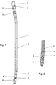
- FIG. 1 shows a side view of a tibia nail
- Fig. 2 shows a section through the distal end region of the tibia nail
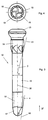
- Fig. 3 is a view of an inventive Locking or clamping screw
- Fig. 4 is a view in Direction of arrow IV of Fig. 3 on the locking screw or clamping screw.
- a Tibialmarknagel 1 is shown, the axis is indicated by dash-dotted lines with 2.
- the axis of the tibia marker nail 1 is here cranked several times and in the direction to the proximal end 3 as well as towards the distal End 4 inclined in the same direction to axis 2 in the central area of the Tibiamarknagels.
- the proximal end has intersecting bores 5 and 6 for the rotation lock.
- the proximal End area provided an elongated hole 7, through which another Locking screw can be inserted, due to the design of the opening as an elongated hole 7 here axial movement of the tibia marker nail 1 and thus dynamization is made possible.
- the distal end 4 again has two bores 8 and 9 with essentially perpendicular to the axis 2 of the bore axis to accommodate locking screws.
- the end region in FIG. 1 is 10 inclined to the rear Bore indicated, which in section in the illustration Fig. 2 is clearly visible.
- this bore 10 is at an angle of approximately 10 ° inclined to the axis 11 of the distal region 4 of the tibia nail arranged so that there is an overall inclination to axis 2 results in the middle area of the tibia nail of about 15 °.
- the holes or perforations 5, 6, 7, 8, 9 and 10 can now conventional locking screws or tension screws be guided to secure anchorage in this way to ensure the tibia nail and, if necessary, additionally Fix splinters successfully.
- suitable tension or locking screw according to the invention is in the 3 and 4 are shown.
- FIG. 3 shows a locking screw 12 which following a screw head 13, a first threaded section 14, a central threadless bolt section 15 and has a terminal threaded portion 16. Outdoors The end of the locking screw is connected to the thread 16 a cutting head 17 is provided, in which, as in particular 4 shows free spaces 18 between threaded sections trained for the removal of the cut material to screw the screw into the bone splitter or to lighten the cortex.
- the middle section 15 of the locking screw is here threadless and has an outer diameter a, which corresponds to the clear cross-section of the tibial nail essentially corresponds.
- the end thread is formed with an outer diameter, which maximum this diameter a of the threadless Area in the middle part, with a definition in Bones on the side opposite the free end the correspondingly larger diameter thread 14 is guaranteed. If the locking screw 12 as a clamping screw to be used, the thread 14 must be smaller Slope as the thread 16 so that when Screwing in a tightening of bone fragments towards the central, threadless region 15 of screw 12 he follows.
- the two are threading portions of threads 14 and 16 in accordance formed with the invention acute-angled.
- the angle, that of the generatrix 19 of the angle-cutting section of the thread 16 with the axis 20 of the screw included is here designated ⁇ and is approximately 10 °.
- For the Angle ⁇ between the generatrix 21 of the thread cutting Section of the thread 14 and the axis 20 was a value of chosen about 15 °.
Priority Applications (1)
| Application Number | Priority Date | Filing Date | Title |
|---|---|---|---|
| AT01890340T ATE266977T1 (de) | 2000-12-18 | 2001-12-17 | Verriegelungsschraube für implantate |
Applications Claiming Priority (2)
| Application Number | Priority Date | Filing Date | Title |
|---|---|---|---|
| AT9232000 | 2000-12-18 | ||
| AT2000923U | 2000-12-18 |
Publications (3)
| Publication Number | Publication Date |
|---|---|
| EP1214914A2 true EP1214914A2 (fr) | 2002-06-19 |
| EP1214914A3 EP1214914A3 (fr) | 2003-07-16 |
| EP1214914B1 EP1214914B1 (fr) | 2004-05-19 |
Family
ID=3502936
Family Applications (1)
| Application Number | Title | Priority Date | Filing Date |
|---|---|---|---|
| EP01890340A Expired - Lifetime EP1214914B1 (fr) | 2000-12-18 | 2001-12-17 | Vis de blocage pour implants |
Country Status (3)
| Country | Link |
|---|---|
| EP (1) | EP1214914B1 (fr) |
| AT (1) | ATE266977T1 (fr) |
| DE (1) | DE50102314D1 (fr) |
Cited By (11)
| Publication number | Priority date | Publication date | Assignee | Title |
|---|---|---|---|---|
| WO2004078049A1 (fr) | 2003-03-07 | 2004-09-16 | Synthes Ag Chur | Vis de blocage pour clou intramedullaire |
| EP1935361A1 (fr) * | 2006-12-19 | 2008-06-25 | Zimmer Technology, Inc. | Système de fixation d'os |
| US7892234B2 (en) | 2004-06-22 | 2011-02-22 | Synthes Usa, Llc | Intramedullary nail |
| US8066706B2 (en) | 2004-06-30 | 2011-11-29 | Synthes Usa, Llc | Surgical nail |
| US8221419B2 (en) | 2003-08-29 | 2012-07-17 | Synthes Usa, Llc | Intramedullary nail |
| US8465489B2 (en) | 2003-06-12 | 2013-06-18 | Synthes Usa, Llc | Surgical nail |
| US8808292B2 (en) | 2008-11-11 | 2014-08-19 | Zimmer Gmbh | Orthopedic screw |
| CN104173099A (zh) * | 2014-08-29 | 2014-12-03 | 南华大学 | 一种微创腰骶椎带锁轴向融合内固定系统锁定螺钉 |
| US9237909B2 (en) | 2003-07-30 | 2016-01-19 | DePuy Synthes Products, Inc. | Surgical nail |
| US9737347B2 (en) | 2003-06-12 | 2017-08-22 | DePuy Synthes Products, Inc. | Surgical nail |
| US9918757B2 (en) | 2001-10-17 | 2018-03-20 | DePuy Synthes Products, Inc. | Bone fixation system |
Citations (3)
| Publication number | Priority date | Publication date | Assignee | Title |
|---|---|---|---|---|
| US5019079A (en) | 1989-11-20 | 1991-05-28 | Zimmer, Inc. | Bone screw |
| EP0695537A1 (fr) | 1994-07-05 | 1996-02-07 | Amp Developpement | Dispositif de vis à tête filetée destinée à permettre la coaptation de deux fragments d'os |
| EP0856293A1 (fr) | 1997-02-04 | 1998-08-05 | Patrice Francois Diebold | Dispositif de vis à tête filetée destiné à pernettre la fixation de petits fragments d'os |
Family Cites Families (2)
| Publication number | Priority date | Publication date | Assignee | Title |
|---|---|---|---|---|
| FR2766355A1 (fr) * | 1997-07-25 | 1999-01-29 | Objectif Implants France | Tige medullaire de prothese, en particulier tige femorale de prothese de hanche |
| FR2787989B1 (fr) * | 1998-12-30 | 2001-07-13 | Depuy France | Vis d'osteosynthese autocompressive pour la chirurgie de petits os |
-
2001
- 2001-12-17 EP EP01890340A patent/EP1214914B1/fr not_active Expired - Lifetime
- 2001-12-17 AT AT01890340T patent/ATE266977T1/de not_active IP Right Cessation
- 2001-12-17 DE DE50102314T patent/DE50102314D1/de not_active Expired - Fee Related
Patent Citations (3)
| Publication number | Priority date | Publication date | Assignee | Title |
|---|---|---|---|---|
| US5019079A (en) | 1989-11-20 | 1991-05-28 | Zimmer, Inc. | Bone screw |
| EP0695537A1 (fr) | 1994-07-05 | 1996-02-07 | Amp Developpement | Dispositif de vis à tête filetée destinée à permettre la coaptation de deux fragments d'os |
| EP0856293A1 (fr) | 1997-02-04 | 1998-08-05 | Patrice Francois Diebold | Dispositif de vis à tête filetée destiné à pernettre la fixation de petits fragments d'os |
Cited By (16)
| Publication number | Priority date | Publication date | Assignee | Title |
|---|---|---|---|---|
| US10271881B2 (en) | 2001-10-17 | 2019-04-30 | DePuy Synthes Products, Inc. | Bone fixation system |
| US9918757B2 (en) | 2001-10-17 | 2018-03-20 | DePuy Synthes Products, Inc. | Bone fixation system |
| US8888779B2 (en) | 2003-03-07 | 2014-11-18 | DePuy Synthes Products, LLC | Locking screw for an intramedullary nail |
| AU2003206600B2 (en) * | 2003-03-07 | 2007-08-23 | Synthes Gmbh | Locking screw for an intramedullary nail |
| EP2263584A3 (fr) * | 2003-03-07 | 2011-04-27 | Synthes GmbH | Vis de blocage pour clou intramédullaire |
| WO2004078049A1 (fr) | 2003-03-07 | 2004-09-16 | Synthes Ag Chur | Vis de blocage pour clou intramedullaire |
| US9737347B2 (en) | 2003-06-12 | 2017-08-22 | DePuy Synthes Products, Inc. | Surgical nail |
| US8465489B2 (en) | 2003-06-12 | 2013-06-18 | Synthes Usa, Llc | Surgical nail |
| US9237909B2 (en) | 2003-07-30 | 2016-01-19 | DePuy Synthes Products, Inc. | Surgical nail |
| US8221419B2 (en) | 2003-08-29 | 2012-07-17 | Synthes Usa, Llc | Intramedullary nail |
| US9814500B2 (en) | 2003-08-29 | 2017-11-14 | DePuy Synthes Products, Inc. | Intramedullary nail |
| US7892234B2 (en) | 2004-06-22 | 2011-02-22 | Synthes Usa, Llc | Intramedullary nail |
| US8066706B2 (en) | 2004-06-30 | 2011-11-29 | Synthes Usa, Llc | Surgical nail |
| EP1935361A1 (fr) * | 2006-12-19 | 2008-06-25 | Zimmer Technology, Inc. | Système de fixation d'os |
| US8808292B2 (en) | 2008-11-11 | 2014-08-19 | Zimmer Gmbh | Orthopedic screw |
| CN104173099A (zh) * | 2014-08-29 | 2014-12-03 | 南华大学 | 一种微创腰骶椎带锁轴向融合内固定系统锁定螺钉 |
Also Published As
| Publication number | Publication date |
|---|---|
| EP1214914B1 (fr) | 2004-05-19 |
| EP1214914A3 (fr) | 2003-07-16 |
| DE50102314D1 (de) | 2004-06-24 |
| ATE266977T1 (de) | 2004-06-15 |
Similar Documents
| Publication | Publication Date | Title |
|---|---|---|
| DE3936703C2 (fr) | ||
| EP1677693B1 (fr) | Plaque d'osteosynthese | |
| EP1096892B1 (fr) | Vis d'osteosynthese, s'utilisant notamment lors d'une fixation par vis vertebrale translaminaire | |
| EP0260222B1 (fr) | Ensemble d'implant pour ostéosynthèse | |
| EP1940306B1 (fr) | Taraud pour former des filets | |
| EP0561295B1 (fr) | Clou intramédullaire à fixation externe | |
| EP0369266B1 (fr) | Vis osseuse | |
| DE60206700T2 (de) | Befestigungsvorrichtung für Knochenteile | |
| EP0654248B1 (fr) | Elément de transfert de charge pour l'ostéosynthèse | |
| DE60213800T2 (de) | Nagel und Schraube für chirurgisches Fixationssystem | |
| DE2807364A1 (de) | Knochenschraube | |
| AT507271B1 (de) | Knochenschraubenset | |
| DE19829228C1 (de) | Vorrichtung zur Versorgung von Knochenbrüchen | |
| DE69726572T2 (de) | Gewindeschneidendes Verankerungselement | |
| EP0209685A2 (fr) | Elément de fixation pour ostéosynthèse | |
| CH666176A5 (de) | Einrichtung zur behandlung eines knochens und nagel fuer eine solche einrichtung. | |
| EP0917449A1 (fr) | Dispositif de fixation de tetes d'articulation de hanche fracturees | |
| WO2002038054A2 (fr) | Vis pour os | |
| EP1214914B1 (fr) | Vis de blocage pour implants | |
| EP1415604A1 (fr) | Système de fixation d'os | |
| DE19831338C2 (de) | Knochenschraube | |
| DE102005058496A1 (de) | Dentalimplantat | |
| WO2004000146A1 (fr) | Vis d'osteosynthese | |
| EP3726072B1 (fr) | Vis pour matériau à base de bois | |
| DE102014208012B3 (de) | Osteosynthesevorrichtung |
Legal Events
| Date | Code | Title | Description |
|---|---|---|---|
| PUAI | Public reference made under article 153(3) epc to a published international application that has entered the european phase |
Free format text: ORIGINAL CODE: 0009012 |
|
| AK | Designated contracting states |
Kind code of ref document: A2 Designated state(s): AT BE CH CY DE DK ES FI FR GB GR IE IT LI LU MC NL PT SE TR |
|
| AX | Request for extension of the european patent |
Free format text: AL;LT;LV;MK;RO;SI |
|
| PUAL | Search report despatched |
Free format text: ORIGINAL CODE: 0009013 |
|
| AK | Designated contracting states |
Designated state(s): AT BE CH CY DE DK ES FI FR GB GR IE IT LI LU MC NL PT SE TR |
|
| AX | Request for extension of the european patent |
Extension state: AL LT LV MK RO SI |
|
| 17P | Request for examination filed |
Effective date: 20030719 |
|
| GRAP | Despatch of communication of intention to grant a patent |
Free format text: ORIGINAL CODE: EPIDOSNIGR1 |
|
| GRAS | Grant fee paid |
Free format text: ORIGINAL CODE: EPIDOSNIGR3 |
|
| GRAA | (expected) grant |
Free format text: ORIGINAL CODE: 0009210 |
|
| AKX | Designation fees paid |
Designated state(s): AT BE CH CY DE DK ES FI FR GB GR IE IT LI LU MC NL PT SE TR |
|
| RAP1 | Party data changed (applicant data changed or rights of an application transferred) |
Owner name: RUPRECHTER, EVA Owner name: BERNSTEINER, HELGA MAG., |
|
| RIN1 | Information on inventor provided before grant (corrected) |
Inventor name: BERNSTEINER, HERBERT Inventor name: RUPRECHTER, EVA Inventor name: HERTZ, HARALD PRIMARIUS |
|
| AK | Designated contracting states |
Kind code of ref document: B1 Designated state(s): AT BE CH CY DE DK ES FI FR GB GR IE IT LI LU MC NL PT SE TR |
|
| PG25 | Lapsed in a contracting state [announced via postgrant information from national office to epo] |
Ref country code: TR Free format text: LAPSE BECAUSE OF FAILURE TO SUBMIT A TRANSLATION OF THE DESCRIPTION OR TO PAY THE FEE WITHIN THE PRESCRIBED TIME-LIMIT Effective date: 20040519 Ref country code: IE Free format text: LAPSE BECAUSE OF FAILURE TO SUBMIT A TRANSLATION OF THE DESCRIPTION OR TO PAY THE FEE WITHIN THE PRESCRIBED TIME-LIMIT Effective date: 20040519 Ref country code: FI Free format text: LAPSE BECAUSE OF FAILURE TO SUBMIT A TRANSLATION OF THE DESCRIPTION OR TO PAY THE FEE WITHIN THE PRESCRIBED TIME-LIMIT Effective date: 20040519 Ref country code: CY Free format text: LAPSE BECAUSE OF FAILURE TO SUBMIT A TRANSLATION OF THE DESCRIPTION OR TO PAY THE FEE WITHIN THE PRESCRIBED TIME-LIMIT Effective date: 20040519 Ref country code: NL Free format text: LAPSE BECAUSE OF FAILURE TO SUBMIT A TRANSLATION OF THE DESCRIPTION OR TO PAY THE FEE WITHIN THE PRESCRIBED TIME-LIMIT Effective date: 20040519 Ref country code: FR Free format text: LAPSE BECAUSE OF FAILURE TO SUBMIT A TRANSLATION OF THE DESCRIPTION OR TO PAY THE FEE WITHIN THE PRESCRIBED TIME-LIMIT Effective date: 20040519 Ref country code: IT Free format text: LAPSE BECAUSE OF FAILURE TO SUBMIT A TRANSLATION OF THE DESCRIPTION OR TO PAY THE FEE WITHIN THE PRESCRIBED TIME-LIMIT;WARNING: LAPSES OF ITALIAN PATENTS WITH EFFECTIVE DATE BEFORE 2007 MAY HAVE OCCURRED AT ANY TIME BEFORE 2007. THE CORRECT EFFECTIVE DATE MAY BE DIFFERENT FROM THE ONE RECORDED. Effective date: 20040519 |
|
| REG | Reference to a national code |
Ref country code: GB Ref legal event code: FG4D Free format text: NOT ENGLISH |
|
| REG | Reference to a national code |
Ref country code: CH Ref legal event code: EP |
|
| REG | Reference to a national code |
Ref country code: IE Ref legal event code: FG4D Free format text: GERMAN |
|
| REF | Corresponds to: |
Ref document number: 50102314 Country of ref document: DE Date of ref document: 20040624 Kind code of ref document: P |
|
| PG25 | Lapsed in a contracting state [announced via postgrant information from national office to epo] |
Ref country code: SE Free format text: LAPSE BECAUSE OF FAILURE TO SUBMIT A TRANSLATION OF THE DESCRIPTION OR TO PAY THE FEE WITHIN THE PRESCRIBED TIME-LIMIT Effective date: 20040819 Ref country code: GR Free format text: LAPSE BECAUSE OF FAILURE TO SUBMIT A TRANSLATION OF THE DESCRIPTION OR TO PAY THE FEE WITHIN THE PRESCRIBED TIME-LIMIT Effective date: 20040819 Ref country code: DK Free format text: LAPSE BECAUSE OF FAILURE TO SUBMIT A TRANSLATION OF THE DESCRIPTION OR TO PAY THE FEE WITHIN THE PRESCRIBED TIME-LIMIT Effective date: 20040819 |
|
| PG25 | Lapsed in a contracting state [announced via postgrant information from national office to epo] |
Ref country code: ES Free format text: LAPSE BECAUSE OF FAILURE TO SUBMIT A TRANSLATION OF THE DESCRIPTION OR TO PAY THE FEE WITHIN THE PRESCRIBED TIME-LIMIT Effective date: 20040830 |
|
| REG | Reference to a national code |
Ref country code: CH Ref legal event code: NV Representative=s name: OK PAT AG PATENTE MARKEN LIZENZEN |
|
| GBT | Gb: translation of ep patent filed (gb section 77(6)(a)/1977) |
Effective date: 20040826 |
|
| NLV1 | Nl: lapsed or annulled due to failure to fulfill the requirements of art. 29p and 29m of the patents act | ||
| PG25 | Lapsed in a contracting state [announced via postgrant information from national office to epo] |
Ref country code: LU Free format text: LAPSE BECAUSE OF NON-PAYMENT OF DUE FEES Effective date: 20041217 Ref country code: AT Free format text: LAPSE BECAUSE OF NON-PAYMENT OF DUE FEES Effective date: 20041217 |
|
| REG | Reference to a national code |
Ref country code: IE Ref legal event code: FD4D |
|
| PG25 | Lapsed in a contracting state [announced via postgrant information from national office to epo] |
Ref country code: BE Free format text: LAPSE BECAUSE OF NON-PAYMENT OF DUE FEES Effective date: 20041231 Ref country code: MC Free format text: LAPSE BECAUSE OF NON-PAYMENT OF DUE FEES Effective date: 20041231 |
|
| PLBE | No opposition filed within time limit |
Free format text: ORIGINAL CODE: 0009261 |
|
| STAA | Information on the status of an ep patent application or granted ep patent |
Free format text: STATUS: NO OPPOSITION FILED WITHIN TIME LIMIT |
|
| 26N | No opposition filed |
Effective date: 20050222 |
|
| EN | Fr: translation not filed | ||
| BERE | Be: lapsed |
Owner name: *RUPRECHTER EVA Effective date: 20041231 Owner name: *BERNSTEINER HELGA MAG. Effective date: 20041231 |
|
| PGFP | Annual fee paid to national office [announced via postgrant information from national office to epo] |
Ref country code: GB Payment date: 20061213 Year of fee payment: 6 |
|
| PGFP | Annual fee paid to national office [announced via postgrant information from national office to epo] |
Ref country code: CH Payment date: 20061221 Year of fee payment: 6 |
|
| PGFP | Annual fee paid to national office [announced via postgrant information from national office to epo] |
Ref country code: DE Payment date: 20061229 Year of fee payment: 6 |
|
| BERE | Be: lapsed |
Owner name: *BERNSTEINER HELGA MAG. Effective date: 20041231 Owner name: *RUPRECHTER EVA Effective date: 20041231 |
|
| PG25 | Lapsed in a contracting state [announced via postgrant information from national office to epo] |
Ref country code: PT Free format text: LAPSE BECAUSE OF NON-PAYMENT OF DUE FEES Effective date: 20041019 |
|
| REG | Reference to a national code |
Ref country code: CH Ref legal event code: PL |
|
| GBPC | Gb: european patent ceased through non-payment of renewal fee |
Effective date: 20071217 |
|
| PG25 | Lapsed in a contracting state [announced via postgrant information from national office to epo] |
Ref country code: LI Free format text: LAPSE BECAUSE OF NON-PAYMENT OF DUE FEES Effective date: 20071231 Ref country code: CH Free format text: LAPSE BECAUSE OF NON-PAYMENT OF DUE FEES Effective date: 20071231 Ref country code: DE Free format text: LAPSE BECAUSE OF NON-PAYMENT OF DUE FEES Effective date: 20080701 |
|
| PG25 | Lapsed in a contracting state [announced via postgrant information from national office to epo] |
Ref country code: GB Free format text: LAPSE BECAUSE OF NON-PAYMENT OF DUE FEES Effective date: 20071217 |