EP1214477B1 - Abbruchvorrichtung mit universellen zinken - Google Patents
Abbruchvorrichtung mit universellen zinken Download PDFInfo
- Publication number
- EP1214477B1 EP1214477B1 EP00957813A EP00957813A EP1214477B1 EP 1214477 B1 EP1214477 B1 EP 1214477B1 EP 00957813 A EP00957813 A EP 00957813A EP 00957813 A EP00957813 A EP 00957813A EP 1214477 B1 EP1214477 B1 EP 1214477B1
- Authority
- EP
- European Patent Office
- Prior art keywords
- claw
- support frame
- tine
- demolition equipment
- claw tine
- Prior art date
- Legal status (The legal status is an assumption and is not a legal conclusion. Google has not performed a legal analysis and makes no representation as to the accuracy of the status listed.)
- Expired - Lifetime
Links
- 210000000078 claw Anatomy 0.000 claims abstract description 263
- 230000000694 effects Effects 0.000 description 15
- 230000007423 decrease Effects 0.000 description 9
- 238000010276 construction Methods 0.000 description 6
- 238000000418 atomic force spectrum Methods 0.000 description 5
- 239000012530 fluid Substances 0.000 description 3
- 230000003247 decreasing effect Effects 0.000 description 2
- 238000003754 machining Methods 0.000 description 2
- 238000010348 incorporation Methods 0.000 description 1
- 238000009434 installation Methods 0.000 description 1
- 239000000463 material Substances 0.000 description 1
- 230000004048 modification Effects 0.000 description 1
- 238000012986 modification Methods 0.000 description 1
- 238000003466 welding Methods 0.000 description 1
Images







Classifications
-
- E—FIXED CONSTRUCTIONS
- E02—HYDRAULIC ENGINEERING; FOUNDATIONS; SOIL SHIFTING
- E02F—DREDGING; SOIL-SHIFTING
- E02F3/00—Dredgers; Soil-shifting machines
- E02F3/04—Dredgers; Soil-shifting machines mechanically-driven
- E02F3/96—Dredgers; Soil-shifting machines mechanically-driven with arrangements for alternate or simultaneous use of different digging elements
- E02F3/965—Dredgers; Soil-shifting machines mechanically-driven with arrangements for alternate or simultaneous use of different digging elements of metal-cutting or concrete-crushing implements
-
- B—PERFORMING OPERATIONS; TRANSPORTING
- B23—MACHINE TOOLS; METAL-WORKING NOT OTHERWISE PROVIDED FOR
- B23D—PLANING; SLOTTING; SHEARING; BROACHING; SAWING; FILING; SCRAPING; LIKE OPERATIONS FOR WORKING METAL BY REMOVING MATERIAL, NOT OTHERWISE PROVIDED FOR
- B23D17/00—Shearing machines or shearing devices cutting by blades pivoted on a single axis
-
- E—FIXED CONSTRUCTIONS
- E02—HYDRAULIC ENGINEERING; FOUNDATIONS; SOIL SHIFTING
- E02F—DREDGING; SOIL-SHIFTING
- E02F3/00—Dredgers; Soil-shifting machines
- E02F3/04—Dredgers; Soil-shifting machines mechanically-driven
- E02F3/28—Dredgers; Soil-shifting machines mechanically-driven with digging tools mounted on a dipper- or bucket-arm, i.e. there is either one arm or a pair of arms, e.g. dippers, buckets
- E02F3/36—Component parts
- E02F3/40—Dippers; Buckets ; Grab devices, e.g. manufacturing processes for buckets, form, geometry or material of buckets
- E02F3/402—Dippers; Buckets ; Grab devices, e.g. manufacturing processes for buckets, form, geometry or material of buckets with means for facilitating the loading thereof, e.g. conveyors
- E02F3/404—Dippers; Buckets ; Grab devices, e.g. manufacturing processes for buckets, form, geometry or material of buckets with means for facilitating the loading thereof, e.g. conveyors comprising two parts movable relative to each other, e.g. for gripping
Definitions
- the present invention relates to a demolition equipment system comprising equipment bases and claw tines, movable between an open and a closed position.
- the present application refers to a demolition equipment system, however, this equipment system is also referred to as construction equipment, scrap handling equipment and the like.
- the description of demolition equipment is not intended to be restrictive of the equipment being referenced.
- demolition equipment it has long been known to utilize elongated extension members, referred to herein as claw tines, in a variety of equipment units.
- claw tines elongated extension members
- a variety of claw tines has been developed for attachment to the buckets to improve the operation of these equipment units. Examples of the wide variety of claw tine attachments for various buckets can be seen in U. S. Patent Nos.
- a demolition equipment system comprising equipment bases and claw tines, movable between an open and a closed position, is further known from JP 11061875 A .
- the present invention provides for a demolition equipment system including a plurality of equipment bases with each equipment base forming at least part of a distinct demolition equipment unit, and each equipment base including a support frame receiver, and a plurality of claw tines, each claw tine is secured to the demolition equipment unit through a support frame and the support frame receiver, such that each claw tine is selectively, removably attached to each equipment base for forming a part of each distinct demolition equipment unit.
- the plurality of equipment bases may include at least one bucket and at least one grapple base.
- the grapple base may, for example, be formed as a two-tine grapple, three-tine grapple, four-tine grapple, or claw structure grapple.
- the two-tine grapple has two opposed claw tines positioned 180 degrees from each other.
- the three-tine grapple has three opposed claw tines positioned 120 degrees from each other and the four-tine grapple has four opposed claw tines positioned 90 degrees from each other.
- the claw structure grapple includes two opposed claw structures, with each claw structure formed of two parallel spaced claw tines with a connecting structure therebetween.
- the claw tine for the demolition equipment system includes an elongated claw tine body pivotally movable about a pivot point between an open position and a closed position.
- a hydraulic cylinder is provided for moving the claw tine body between the open position and the closed position with a fixed end of the hydraulic cylinder secured to a base and a cylinder rod end of the hydraulic cylinder secured to the claw tine body.
- the ratio of the length of the hydraulic cylinder when the claw tine body is in the closed position to the distance between the pivot point and the securement of the cylinder rod end or the hydraulic cylinder to the claw tine body is between 0.7 and 0.9.
- the total angular rotation of the claw tine may be designed to be at least 75 degrees, preferably at least 85 degrees, or generally between 75 and 100 degrees. Additionally, the claw tine may provide a maximum holding force located at 25 to 40 degrees from the closed position, preferably about one third from the closed position.
- the claw tine is secured to the demolition equipment unit through a support frame and a support frame receiver.
- the support frame includes a bushing member for forming the pivot point for the claw tine body and at least one support frame plate attached thereto.
- the support frame plate includes a locking pin aperture for securing the support frame to the demolition equipment through the support frame receiver and a securing pin aperture for securing a fixed end of the hydraulic cylinder to the support frame.
- the support frame receiver is a single plate structure attached to the demolition equipment and including an opening for receiving the bushing member of the support frame and a locking pin aperture aligned with the locking pin aperture of the support frame for securing the support frame to the demolition equipment.
- Each claw tine may have a removable claw tip at a distal end of the claw tine body.
- the claw tine may be associated with a parallel spaced claw tine and a connecting structure therebetween to form a claw structure.
- the connecting structure may include a grid and an end member extending between and coupled to the spaced claw tines.
- Fig. 1 schematically illustrates a bucket 10 with a claw structure according to the present invention coupled thereto.
- the claw structure includes at least one claw tine 12 pivotally attached to the bucket 10 for movement about a pivot point 14.
- a hydraulic cylinder 16 is positioned generally within the claw tine 12 and has one end thereof pinned to the bucket 10 at a fixed end 18 and secured to the claw tine 12 at a cylinder rod end 20.
- the claw tine 12 of the present invention encloses and protects the hydraulic cylinder 16.
- the hydraulic cylinder 16 provides power for moving the claw tine 12 between the open and closed positions illustrated in Fig. 1 .
- Fig. 2 better illustrates the important linkage parameters associated with the claw tine 12.
- the distance between the main pivot point 14 and the fixed end 18 of the hydraulic cylinder 16 is a lever arm R of the linkage.
- THETA is the relative angular orientation of the fixed end 18 of the cylinder 16 to the pivot point 14 measured from the horizontal.
- the lever arm R and angular orientation THETA represent two linkage parameters having a major effect on the output characteristics of the claw tine 12 and associated claw structure.
- the location of the cylinder rod end 20 with respect to the pivot point 14 also has a major effect on the performance of the claw tine 12 and associated claw structure.
- This relative relationship is defined by as distance Z between the pivot point 14 and the cylinder rod end 20 as well as the relative angle therebetween labeled BETA, which is measured from vertical as shown in Fig. 2 .
- a vertical distance Y between the pivot point 14 and the tip of the claw tine 12 is the lever arm of the holding force developed at the tip of the claw tine 12.
- a distance X is the horizontal distance from the pivot point 14 to the leading edge of the end of the claw tine 12.
- Fig. 2 illustrates values RX and RY which represent relative distances from the cylinder rod end 20 to the end of the tip of the claw tine 12.
- the size and shape of the end of the claw tine 12 dictate a minimum distance from the end of the claw tine 12 and the cylinder rod end 20.
- FIG. 2 Another important parameter labeled in Fig. 2 is the angle between the center line of the hydraulic cylinder and the lever arm R of the claw structure.
- ALPHA This angle will be referred as ALPHA which will vary as the claw tine 12 moves from the closed position to the open position.
- This angular relationship will have an effect on the holding force developed in the various positions.
- the holding force will increase as the claw opens from the fully closed position to a maximum value and then decreases until the fully open position is reached.
- the claw tine 12 can be designed so that the sinusoidal shaped force versus angular position curve maximizes the holding force in a desired location by varying the main geometric parameters of the linkage.
- the total possible angular rotation of the claw tine 12 with respect to the bucket 10, or other associated base is controlled by two main considerations. First, care must be taken to ensure that the claw tine 12 does not strike any part of the host machine during any possible movement of the bucket 10 or other structure. Second, the total possible rotation of the claw tine 12 has to be limited due to the hydraulic cylinder 16, once selected. The amount of stroke that can be obtained from a hydraulic cylinder is limited by its fully retracted length and the size of the internal components of the cylinder. Therefore, the cylinder that fits the design when the cylinder is fully retracted (claw tine 12 in the fully opened position) may not have sufficient stroke to produce the desired total rotation of the claw tine 12.
- the magnitude of the maximum holding force is not a function of angle THETA, but the angular position of the claw tine 12 where the maximum holding force occurs is effected by THETA.
- Increasing the magnitude of THETA causes the sinusoidal force curve to shift away from the closed position toward the open position of the claw tine 12. Consequently, increasing THETA increases the holding force at the open position and decreases the holding force at the closed position.
- Changes in the angle THETA have only a minor effect on the length of the stroke and the cylinder 16 in either position. How the change in the angle THETA will effect the length of the stroke of hydraulic cylinder 16 and the length of the cylinder 16 will vary depending on the value of the distance Z.
- Varying the distance Z does not effect the magnitude of the holding force, but increasing this distance will shift the holding force curve toward the claw tine 12 closed position.
- the force at the closed position and the force at the open position decreases as the distance Z increases.
- the cylinder lengths in both the open and closed positions increase as distance Z increases.
- the magnitude of the distance Z has only a minor effect on the needed cylinder stroke and it may increase or decrease the stroke depending on the values of R and BETA discussed above.
- the angle BETA has an initial value and BETA increases from the initial value as the claw tine 12 rotates from the closed position to the open position.
- the total change in BETA is equal to the total angular rotation of the claw tine 12 and the associated claw structure.
- the initial value of BETA in the closed position has an effect on the operating parameters of the design. Increasing the initial value of BETA shifts the holding force curve toward the closed claw tine position having the same type of effect as increasing the distance Z discussed above. Changes in the angle BETA cause a relatively greater shift in the holding force curve than similar percentage changes to the distance Z. Change in the initial angle BETA have only a minor effect on the needed cylinder stroke and cylinder lengths in the open and closed positions. Whether these lengths increase or decrease depends on the value of THETA as well as the value of BETA.
- the values of the distances X and Y are largely a function of the size and shape of the associated machine. If the claw tine 12 is associated with a given bucket 10, these values are largely predetermined. Movement of the location of the pivot point 14 can vary the values for X and Y slightly for a given structure. Increasing the value of Y, the lever arm of the holding force, reduces the magnitude of the holding force in all angular positions of the claw tine 12. The distance X effects the initial value of the angle BETA such that increasing X, increases the initial angle BETA. The movement of the pivot point 14 is limited by interference problems in typical bucket configurations. In general, the overall performance of the claw tine 12 will improve if the value of Y is as small as possible while avoiding the above-mentioned interference. Increasing the value of X increases the length of the cylinder 16 in the open claw position. Increasing the value of X can help overcome possible limitations to the desired total angular rotational values of the claw tine 12 due to the limitations of the hydraulic cylinder 16 discussed above.
- the variables RX and RY will also effect the distance Z and initial angle BETA.
- Increasing RX increases the value of Z and the initial value of BETA.
- Increasing the value of RY decreases the value of Z while increasing the initial value of BETA.
- Z decreases in magnitude, the total possible angle of rotation of the claw tine 12 will usually be limited by the closed cylinder length and the required cylinder stroke. Under this condition, the distance RY should be decreased and the value RX should be increased to help overcome this problem.
- the force of the claw structure formed by one or more claw tines 12 is determined by the hydraulic cylinders 16. It is possible to design a claw structure with a different number of hydraulic cylinders 16.
- the holding force can be increased by increasing the diameter of, or the number of, hydraulic cylinders used in the design of a claw structure.
- Increasing the diameter of the cylinders in total claw structures will increase the opening and closing times for the structure.
- the opening and closing times, also known as cycle times, for a given claw structure are also a function of the hydraulic fluid flow rate produced by the pumps of the associated machine.
- the hydraulic pressure and pump flow rate are determined by the design of the.host machine and are not specifically design variables considered in the claw tines 12 for the specific claw structure geometry.
- the geometric parameters most effecting the magnitude of the holding forces are the length of the lever arm R and the holding force lever arm Y. Since the value for the variable Y is largely a function of the bucket or other structure on which the claw tine is associated, the lever arm R is preferably made as large as possible for a given claw tine 12. Increasing the magnitude of R increases the need for cylinder stroke and decreases the cylinder length in the open position. The magnitude of R is effectively limited by both the cylinder length considerations and possible structural interference with the associated machine when in the fully open position. Another way for the designer to increase the holding force is by increasing the size and number of hydraulic cylinders. The limiting factors on this design consideration are the increased cycle time of the assembly along with the increased cost of the larger hydraulic components.
- a designer of the claw tine 12 according to the present invention can position the location of the holding force curve with respect to the angular position of the claw tine 12 by varying the geometric parameters THETA, Z and BETA as discussed above.
- the total angle of rotation that the claw tine 12 and the associated claw structure can undergo from the closed to open position is limited by the length of the stroke and the open positioned cylinder lengths along with possible interferences with the associated machine.
- the improved claw tine 12 according to the present invention provides the value of the angle ALPHA in the open position such that the maximum holding force of the structure will occur when the claw tine is between 25 and 40 degrees from the closed position. Maximizing the holding force versus the angular position of the claw tine in this specific range will result in the best overall performance of the demolition equipment having a claw tine 12 according to the present invention.
- another important design consideration of the present invention is having a value of the geometric ratio between the retracted cylinder length divided by the distance Z fall generally between 0.7 and 0.9.
- This ratio will control the symmetry of the various sizes for the claw tine 12 and allow for all of the designs to have a maximum total angular rotation generally between 75 and 100 degrees.
- the claw tine 12 is specifically designed to satisfy these design considerations. Additionally, these design considerations allow for the claw tine 12 to be adapted for use on a bucket 10 as shown in Fig. 1 or a wide variety of other configurations as will be described hereinafter.
- Fig. 3 is a detailed view of the bucket 10 with a claw structure according to the present invention incorporating a pair of claw tines 12.
- the tip of each claw tine 12 is formed of a removable end member 22 attached to and extending between the parallel spaced claw tines 12.
- the end member 22 has a plurality of spaced teeth 24 extending therefrom.
- the teeth 24 of the end member 22 are positioned between teeth 26 of the bucket 10.
- the claw structure additionally includes a grid 28 having openings of a given size extending between and removably attached to the pair of claw tines 12.
- the pair of claw tines 12, end member 22 with associated teeth 24, and grid 28 combine to form the claw structure associated with the bucket 10.
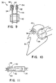
- Each claw tine 12 is secured to the bucket 10 through a support frame 30 shown in detail in Figs. 7-9 and a support frame receiver 32 which is shown in detail in Figs. 10 and 11 .
- the support frame receiver 32 is welded to the bucket 10 or otherwise securely attached in the desired location.
- the support frame receiver 32 is a single plate having a generally C-shaped opening 34 at one end thereof which receives the structure forming the pivot point 14 as will be described hereinafter.
- An enlarged portion 36 of the support frame receiver 32 surrounds the C-shaped opening 34 and is wider than the remaining portions of the plate forming a support frame receiver 32 to provide increased stability to the associated claw tine 12.
- the enlarged portion 36 surrounding the opening 34 can be made integral with the remaining portions of the support frame receiver 32 or, may be made as a separate replaceable element if this location is determined to be in an area of wear.
- the support frame receiver 32 additionally includes a locking pin aperture 38 at a position generally behind the C-shaped opening 34.
- An enlarged portion 40 surrounds the locking pin aperture 38 as illustrated in the drawings.
- the support frame 30 includes a cylindrical bushing member 42 and a pair of support frame plates 44 extending therefrom.
- the support frame plates 44 include a locking pin aperture 46 and support structure 48 surrounding the locking pin aperture 46 on each support frame plate 44.
- One support structure 48 can include a cross pin aperture 50 as shown in Fig. 8 .
- the support frame plates 44 additionally include a securing pin aperture 52 for receiving the fixed end 18 of the hydraulic cylinder 16.
- the securing pin aperture 52 is surrounded by support structure 54 on each support frame plate 44.
- One support structure 54 includes a cross pin aperture 56 extending therethrough as shown in Fig. 8 .
- each claw tine 12 is secured to the bucket 10 through the support frame 30 and support frame receiver 32.
- the support frame receiver 32 is welded or otherwise secured to the bucket 10.
- the support frame 30 is positioned so that the bushing member 42 is received in the C-shaped opening 34 of the support frame receiver 32 such that the locking pin aperture 46 aligns with locking pin aperture 38.
- Locking pin 58 extends through the locking pin aperture 38 and the locking pin aperture 46 securing the support frame 30 and the associated claw tine 12 to the bucket 10.
- a cross locking member 60 can extend through the cross pin aperture 50 to prevent the locking pin 58 from sliding out of engagement.
- the bushing member 42 provides for the pivot point 14 of the claw tine 12.
- the bushing member 42 receives a pair of replaceable bushings 62 which surround a pivot pin 64.
- the pivot pin 64 is attached to the claw tine body 66 through cross locking members 68 such as conventional bolts.
- the fixed end 18 of the hydraulic cylinder 16 is secured to the support frame 30 by securing pin 70 extending through securing pin apertures 52 in the support frame plates 44.
- the securing pin 70 can be held in position by a cross locking member 68 extending through cross pin aperture 56.
- Fig. 6 illustrates the connection of the cylinder rod end 20 of the hydraulic cylinder 16 to the claw tine body 66 through an attachment pin 74.
- the attachment pin 74 may be in the form of a convention nut and bolt or other type attaching pin configuration as known in the art.
- Fig. 6 additionally illustrates the abutment of the end member 22 to the claw tine 12.
- the end member 22 may be welded or otherwise attached to the claw tine 12.
- a component is also a "releasable connection”.
- the hydraulic cylinder 16 for operating the individual claw tines 12 and the associated claw structure is a double acting cylinder controlled in the conventional fashion.
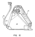
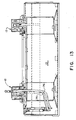
- Figs. 12 and 13 illustrate the positioning of the hydraulic elements for individual hydraulic cylinders 16 of the claw tines 12. As shown in Figs. 12 and 13 , each side of the piston of hydraulic cylinder 16 is fed with a hydraulic line 76. As shown in Figs. 12 and 13 , the hydraulic lines 76 do not interfere with the operation of the bucket 10.
- the claw tine 12 of the present invention is designed to be utilized in a wide variety of construction equipment.
- the end members 22 and grid 28 are specifically provided to be removably coupled to the claw tine 12 so that the claw structure can be easily disassembled for repair and/or incorporation of the claw tines 12 into other construction equipment.
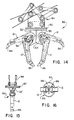
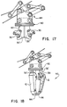
- Figs. 14-17 illustrate a two-tine grapple 80 utilizing the claw tines 12.
- the two-tine grapple 80 includes a (powered or non-powered)rotatable base 82 which includes two integral support frame receivers 32' positioned 180 degrees relative to each other as illustrated in Fig. 17 .
- Each claw tine 12 is attached to the rotatable base 82 through support frame 30 and support frame receiver 32' in the same manner discussed above in connection with bucket 10.
- the rotatable base 82 will be supported and controlled in a conventional fashion.
- the support for the rotatable base 82 is schematically illustrated at 84.
- the ends of the individual claw tines 12 are provided with individual replaceable tips 86.
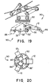
- Figs. 18-20 illustrate a three-tine grapple 90 utilizing the claw tines 12 of the present invention.
- the three-tine grapple 90 is similar to the two-tine grapple 80 discussed in Figs. 14-17 and includes a rotatable base 92.
- Rotatable base 92 includes three integral support frame receivers 32' positioned at 120 degrees relative to each other.
- the three claw tines 12 forming the three-tine grapple 90 may utilize replaceable tips 86 or may have a modified tip 86' as shown in Fig. 20 .
- the modified tips 86' have beveled edges to permit a closer closed position of the tines 12.
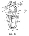
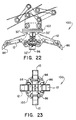
- Figs. 21-23 illustrate a four-tine grapple 100 utilizing four claw tines 12.
- the four-tine grapple 100 is similar to the three-tine grapple 90 and the two-tine grapple 80 discussed above and includes a rotatable base 102.
- the rotatable base 102 has four integral support frame receivers 32' positioned at 90 degrees relative to each other for attaching each of the four claw tines 12 through the associated support frame 30.
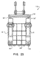
- Figs. 24-26 illustrate a claw structure grapple 110 utilizing four claw tines 12.
- the claw structure grapple 110 includes a rotatable base 112 with two pairs of opposed integral support frame receivers 32' spaced from each other.
- the spaced set of opposed support frame receivers 32' allow for two sets of opposed claw tines 12 to be attached to the rotatable base 112.
- the claw tines 12 on each side of the rotatable base 112 will be secured together to form a claw structure similar to the claw structure on the bucket 10.
- an end member 22 and grid 28 can be secured between the pair of parallel spaced claw tines 12 to form two opposed claw structures as best illustrated in Figs. 25 and 26 .
- Figs. 27 and 28 illustrate a claw tine 12' designed for a different sized bucket 10' than illustrated in Fig. 3 .
- the embodiment illustrated in Figs. 27 and 28 is intended to illustrate that changes in the size do not significantly effect the design of the overall claw tine 12 or 12'.
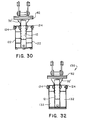
- Figs. 29 and 30 illustrate a two tine rotary grapple 120 utilizing the claw tines 12 of the present invention.
- the grapple 120 is similar to the grapple 80 of Figs. 14-17 and includes the same rotatable base 82 having two integral support frame receivers 32'. Each claw tine 12 is attached to the rotatable base 82 through support frame 30 and support frame receiver 32' in the same manner discussed above in connection with bucket 10.
- the grapple 120 includes a pair of outboard grates 122 mounted on the sides of each tine 12.
- a support linkage 124 extends between opposed outboard grates 122 for additional support.
- the support linkage 124 is attached about the pivot axis of each tine 12.
- Grapple 120 represents an alternative design for a grated claw structure.
- Figs. 31-33 illustrate a two tine rotary clamshell bucket 130 utilizing the claw tines 12 of the present invention.
- the clamshell bucket 130 is similar to the grapple 120 of Figs. 29-30 and includes the same rotatable base 82 having two integral support frame receivers 32'. Each claw tine 12 is attached to the rotatable base 82 through support frame 30 and support frame receiver 32' in the same manner discussed above in connection with bucket 10.
- the clamshell bucket 130 includes a pair of outboard bucket members 132 mounted on the sides of each tine 12.
- a support linkage 124 extends between opposed bucket members 132 for additional support.
- the support linkage 124 is attached about the pivot axis of each tine 12.
- the bucket members 132 are designed to combine with the tines 12 to form a generally closed bucket when in the closed position.
- the clamshell bucket 130 represents an alternative design for a tool which is adapted for granular type work or the like.
- the bucket members 132 extending from each side of the tine 12 could be replaced with a single bucket member for each tine 12 positioned in front or behind the tine 12, depending on the desired bucket size.
- Figs. 34 and 35 illustrate a three tine rotary orange peel grapple 140 utilizing the claw tines 12 of the present invention.
- the grapple 140 is similar to the grapple 90 of Figs. 18-20 and includes the same rotatable base 92 having three integral support frame receivers 32' for mounting three claw tines 12.
- Each claw tine 12 is attached to the rotatable base 92 through support frame 30 and support frame receiver 32' in the same manner discussed above in connection with bucket 10.
- the grapple 140 includes an orange peel bucket member 142 mounted on each tine 12.
- the bucket members 142 are designed to combine to form a generally closed bucket when the tines 12 are in the closed position.
- Grapple 140 represents an alternative design which is adapted for granular type work or the like.
- the bucket members 142 are positioned in front of the tines 12 but could be replaced with a pair of members extending from each side of the tine 12 or positioned behind the tine 12, depending on the desired bucket size.
- the orange peel refers to the shape of the individual bucket members 142.
- Figs. 36 and 37 illustrate a fork assembly 150 including a pair of tines 12 forming a claw attachment for a conventional pair of forks 152.
- the claw attachment is substantially the same as the claw structure of Fig. 3 and the embodiment illustrated in Figs. 27 and 28 .
- Figs. 36 and 37 illustrate further variations in tool design using the universal tine 12 of the present invention.
- the design considerations discussed above provide an efficient and effective tine for use both in a bucket attachment and other configurations.
- the advantages of the present invention include a rugged construction which is adaptable to any bucket and in multiple tool configurations.
- the present design provides interchangeability among tool set components and for quick installation and removal of tool sets.
- the present invention provides a shielded power/hydraulic system.
- the use of a single support frame receiver 32 or 32' is believed to be significantly easier than prior art structures which require multiple plates and significant machining and modification to have the parallel plates properly positioned on an existing bucket.
- the present invention contemplates providing a demolition equipment system in which the universal claw tine 12 can be utilized in a wide variety of demolition equipment units.
- the same set of four claw tines 12 can be utilized in various combinations to form a claw structure attachment for a bucket 10, a two-tine grapple 80, a three-tine grapple 90, a four-tine grapple 100, a claw structure grapple 110, a clamshell bucket 130, an orange peel grapple 140, or a claw structure for fork assembly 150. It is additionally contemplated that when using the claw structure for the bucket 10, the claw structure grapple 110, or the fork assembly 150 separate grids 28 can be utilized having different sized openings. The different sized openings in the different grids 28 can be utilized for segregating material in a sieve like fashion.
- the demolition equipment system provides a wide variety of equipment at a minimal capital cost. Additionally, the easy disassembly of the claw tines 12 from the respective demolition equipment units facilitates easy repair of the individual demolition equipment units.
- the bucket 10, rotatable base 82, rotatable base 92, rotatable base 102, rotatable base 112 and the forks 152 all form an equipment base for attachment of the claw tines 12.
Landscapes
- Engineering & Computer Science (AREA)
- Mechanical Engineering (AREA)
- Structural Engineering (AREA)
- Mining & Mineral Resources (AREA)
- Civil Engineering (AREA)
- General Engineering & Computer Science (AREA)
- Load-Engaging Elements For Cranes (AREA)
- Soil Working Implements (AREA)
- Shovels (AREA)
- Cultivation Of Plants (AREA)
- Manufacture And Refinement Of Metals (AREA)
- Telephone Function (AREA)
Claims (24)
- Abbruchvorrichtung, umfassend Vorrichtungsbasisteile und Greiferklauen, die zwischen einer offenen und einer geschlossenen Stellung bewegbar sind, gekennzeichnet durch eine Vielzahl von Vorrichtungsbasisteilen (80, 90, 100), wobei jedes Vorrichtungsbasisteil (80, 90, 100) mindestens einen Teil einer speziellen Abbruchvorrichtungseinheit bildet und wobei jedes Vorrichtungsbasisteil (80, 90, 100) eine Trägerrahmenaufnahme (32) und eine Vielzahl von Greiferklauen (12) aufweist, wobei jede Greiferklaue (12) mittels eines Trägerrahmens (30) und einer Trägerrahmenaufnahme (32) derart an der Abbruchvorrichtungseinheit gesichert ist, dass jede Greiferklaue (12) wahlweise und beweglich an jedem Vorrichtungsbasisteil (80, 90, 100) befestigt ist, um so einen Teil jeder speziellen Abbruchvorrichtungseinheit zu bilden.
- Abbruchvorrichtung nach Anspruch 1, dadurch gekennzeichnet, dass die Vielzahl der Vorrichtungsbasisteile (80, 90, 100) mindestens eine Schaufel (10) und mindestens eine Mehrschalengreiferbasis umfasst.
- Abbruchvorrichtung nach Anspruch 2, dadurch gekennzeichnet, dass mindestens eine Mehrschalengreiferbasis ein zweizackiger Greifer (80) mit einem Paar sich einander gegenüber befindlicher und um 180 Grad von einander entfernter Greiferklauen (12) ist.
- Abbruchvorrichtung nach Anspruch 2, dadurch gekennzeichnet, dass mindestens eine Mehrschalengreiferbasis ein dreizackiger Greifer (90) mit drei jeweils aufeinander zu gerichteten Greiferklauen (12) ist, die ungefähr in 120 Grad-Abständen voneinander angeordnet sind.
- Abbruchvorrichtung nach Anspruch 2, dadurch gekennzeichnet, dass mindestens eine Mehrschalengreiferbasis ein vierzackiger Greifer (100) mit vier einander gegenüber stehenden Greiferklauen (12) ist, wobei jede Greiferklaue (12) um 90 Grad entfernt von zwei benachbarten Greiferklauen (12) angeordnet ist.
- Abbruchvorrichtung nach Anspruch 1, dadurch gekennzeichnet, dass mindestens eine Abbruchvorrichtungseinheit mindestens ein Paar beabstandeter, parallel angeordneter Greiferklauen (12) aufweist, die zusammengekoppelt sind, um eine Greiferstruktur zu bilden.
- Abbruchvorrichtung nach Anspruch 6, dadurch gekennzeichnet, dass die Greiferstruktur ein die Spitzen der Greiferklauen (12) bildendes Endteil (22) umfasst, welches sich zwischen den beabstandeten Greiferklauen (12) erstreckt und an diesen befestigt ist.
- Abbruchvorrichtung nach Anspruch 1, dadurch gekennzeichnet, dass die Greiferstruktur mindestens einer Abbruchvorrichtungseinheit eine Gitteranordnung (28) umfasst, die mit mindestens einer mit einem Zwischenraum versehenen Greiferklaue (12) demontierbar verbunden ist.
- Abbruchvorrichtung nach Anspruch 1, dadurch gekennzeichnet, dass jede Greiferklaue (12) einen verlängerten Greiferklauenkörper (66), der drehbar um einen Drehzapfen (14) zwischen der geöffneten und der geschlossenen Stellung beweglich angeordnet ist, und einen Hydraulikzylinder (16) zur Bewegung des Greiferklauenkörpers (66) zwischen der geöffneten und der geschlossenen Stellung umfaßt, wobei der Hydraulikzylinder (16) ein feststehendes, mit der Basis verbundenes und ein mit der Kolbenstange (20) am Greiferklauenkörper (66) befestigtes Ende aufweist, und wobei der Wert des geometrischen Verhältnisses zwischen der Länge des eingefahrenen Hydraulikzylinders (16), z.B. wenn sich der Greiferklauenkörper (66) in geschlossener Stellung befindet, dividiert durch die Distanz (Z) zwischen dem Drehzapfen (14) und der Stellung, in der das Ende der Kolbenstange (20) des Hydraulikzylinders (16) am Greiferklauenkörper (66) befestigt ist, im Allgemeinen zwischen 0.7 und 0.9 liegt.
- Abbruchvorrichtung nach Anspruch 1, dadurch gekennzeichnet, dass jede Greiferklaue (12) einen verlängerten Greiferklauenkörper (66), der um einen Drehzapfen (14) zwischen geöffneter und geschlossener Stellung drehbar und bewegbar angeordnet ist, einen Hydraulikzylinder (16) zur Bewegung des Greiferklauenkörpers (66) zwischen geöffneter und geschlossener Stellung, und einen Trägerrahmen (30) zur Befestigung der Greiferklaue (12) an der Abbruchvorrichtungseinheit umfaßt, wobei der Trägerrahmen (30) eine zylindrische, den Drehpunkt des Greiferklauenkörpers (66) bildende Lagerbuchse (42), und mindestens eine Stützrahmenfußplatte (44), die mit der Lagerbuchse (42) verbunden ist, eine Steckbolzenöffnung (46) in der Stützrahmenfussplatte (44) zur Verbindung des Trägerrahmens (30) mit der Abbruchvorrichtungseinheit und eine Sicherungsstiftöffnung (52) in der Trägerrahmenfussplatte (44) zur Befestigung des festen Endes des Hydraulikzylinders (16) am Trägerrahmen (30) und eine Trägerrahmenaufnahme (32), die an der Abbruchvorrichtungseinheit befestigt ist, umfaßt, und wobei die Trägerrahmenaufnahme (32) als einzelne, mit einer Öffnung zur Aufnahme der Lagerbuchse (42) versehene Platte und mit einer Steckbolzenöffnung ausgeführt ist, die mit der Steckbolzenöffnung (42) des Trägerrahmens (30) fluchtet, um den Trägerrahmen (30) mit der Abbruchvorrichtungseinheit zu verbinden.
- Abbruchvorrichtung nach Anspruch 1, dadurch gekennzeichnet, dass der verlängerte Greiferklauenkörper (66) der Greiferklaue (12) zwischen einer offenen und einer geschlossenen Stellung um einen festen Drehzapfen (14) bewegbar ist, dass die Greifenklaue (12) sich bis zu dem distalen Ende des Greiferkörpers (66) erstreckt und dass ein Hydraulikzylinder (16) zur Bewegung des Greiferklauenkörpers (66) zwischen der offenen und der geschlossenen Stellung vorgesehen ist, wobei der Hydraulikzylinder (16) ein festes Ende (18), das mit einer Basis (Schaufel 10) verbunden ist, und ein Ende der Kolbenstange (20), die mit dem Greiferklauenkörper (66) verbunden ist, umfasst, wobei der gesamte Drehwinkelausschlag des Greiferklauenkörpers (66) zwischen der offenen und der geschlossenen Stellung mindestens 75 Grad beträgt.
- Abbruchvorrichtung nach Anspruch 11, dadurch gekennzeichnet, dass das Verhältnis zwischen der Länge des Hydraulikzylinders (16), wenn sich der Greiferklauenkörper (66) in geschlossener Stellung befindet, zum Abstand zwischen den Drehzapfen (14) und der Stellung, in der das Ende der Kolbenstange (20) des Hydraulikzylinders (16) am Greiferklauenkörper (66) befestigt ist, im Bereich zwischen 0.7 bis 0.9 liegt.
- Abbruchvorrichtung nach Anspruch 11, dadurch gekennzeichnet, dass die gesamte Drehung des Greiferklauenkörpers (66) zwischen der offenen und der geschlossenen Stellung zwischen 75 und 100 Grad beträgt.
- Abbruchvorrichtung nach Anspruch 11, dadurch gekennzeichnet, dass der gesamte Drehwinkelausschlag der Greifenklaue (12) mindestens 85 Grad beträgt.
- Abbruchvorrichtung nach Anspruch 11, dadurch gekennzeichnet, dass eine maximale Haltekraft der Greifenklaue (12) zwischen 25 und 40 Grad von der geschlossenen Stellung liegt.
- Abbruchvorrichtung nach Anspruch 11, dadurch gekennzeichnet, dass diese zusätzlich einen Trägerrahmen (30) zur Befestigung der Greiferklaue (12) an der Abbruchvorrichtungseinheit, wobei der Trägerrahmen (30) eine zylindrische Lagerbuchse (42) einschließt, die einen Drehpunkt für den Greiferklauenkörper (66) bildet, mindestens einen mit der Lagerbuchse (42) verbundenen Trägerrahmensockel (44), eine Steckbolzenöffnung (38), die im Trägerrahmensockel (44) zur Befestigung des Trägerrahmens (30) an der Abbruchvorrichtung angeordnet ist, und eine Sicherungsbolzenöffnung (46), die im Trägerrahmensockel (44) zur Fixierung des festen Endes (18) des hydraulischen Zylinders (16) am Trägerrahmen (30) ausgebildet ist, und eine Stützrahmenaufnahme (32), die an der Abbruchvorrichtung befestigt ist, umfaßt, wobei die Trägerrahmenaufnahme (32) als eine einzelne Platte mit einer Öffnung zur Aufnahme der Lagerbuchse (42) und mit einer Sicherungsbolzenöffnung (46), die mit einer Sicherungsbolzenöffnung (38) des Trägerrahmens (30) fluchtet, zur Verbindung des Trägerrahmens (30) mit der Abbruchvorrichtungseinheit ausgeführt sind.
- Abbruchvorrichtung nach Anspruch 1, dadurch gekennzeichnet, dass der verlängerte Greiferklauenkörper (66) der Greiferklaue (12) um einen Drehzapfen (14) zwischen einer offenen und einer geschlossenen Stellung drehbar bewegbar ist, dass ein Hydraulikzylinder (66) zur Bewegung des Greiferklauenkörpers (66) zwischen der offenen und der geschlossenen Stellung vorgesehen ist, und dass ein Trägerrahmen (30) zur Befestigung der Greiferklaue (12) an der Abbruchvorrichtung vorhanden ist, wobei der Trägerrahmen (30) eine zylindrische Lagerbuchse (42), die einen Drehzapfen für den Greiferklauenkörper (66) bildet, und mindestens einen Trägerrahmensockel (44), der mit der Lagerbuchse (30) verbunden ist, eine Steckbolzenöffnung (38) zur Befestigung des Trägerrahmens (30) an der Abbruchvorrichtung und eine im Stützrahmensockel (44) vorhandene Sicherungsbolzenöffnung (46) zur Befestigung des festen Endes des Hydraulikzylinders (16) am Trägerrahmen (30) und eine Trägerrahmenaufnahme (32), die an der Abbruchvorrichtung befestigt ist, aufweist, wobei die Trägerrahmenaufnahme (32) als eine einzelne Platte mit einer Öffnung (34) zur Aufnahme der Lagerbuchse (42) und mit einer Sicherungsbolzenöffnung (46) ausgeführt ist, die mit der Sicherungsbolzenöffnung (38) des Trägerrahmens (30) zur Befestigung des Trägerrahmens (30) an der Abbruchvorrichtung fluchtet.
- Abbruchvorrichtung nach Anspruch 17, dadurch gekennzeichnet, dass die Trägerrahmenaufnahme (32) einen erweiterten Bereich (36) umfaßt, der die die Lagerbuchse (42) aufnehmende Öffnung (34) umgibt, wobei der erweiterte Bereich (36) breiter als die benachbarten Teile der Trägerrahmenaufnahme (32) ist.
- Abbruchvorrichtung nach Anspruch 17, dadurch gekennzeichnet, dass diese zusätzlich eine demontierbare Greiferspitze (Endteil 22) am distalen Ende des Greiferkörpers (12) umfaßt.
- Abbruchvorrichtung nach Anspruch 17, dadurch gekennzeichnet, dass die Greiferklaue (12) derart ausgeführt ist, dass diese einen gesamten Drehwinkelausschlag von mindestens 75 Grad aufweist.
- Abbruchvorrichtung nach Anspruch 1, dadurch gekennzeichnet, dass der verlängerte Greiferklauenkörper (66) der Greiferklaue (12) um einen Drehzapfen zwischen einer offenen und einer geschlossenen Stellung bewegbar ist, dass sich die Greiferklaue (12) bis zum distalen Ende des Greiferklauenkörpers (66) erstreckt und dass ein Hydraulikzylinder (16) zur Bewegung des Greiferklauenkörpers (66) zwischen der offenen und der geschlossenen Stellung vorgesehen ist, wobei der Hydraulikzylinder (16) ein feststehendes Ende (18), welches mit einer Basis (Schaufel 10) und einem Ende der Kolbenstange (20) verbunden ist, das am Greiferklauenkörper (66) befestigt ist, umfaßt, und wobei die maximale Haltekraft der Greiferklaue (12) erreicht wird, wenn sich diese ungefähr bei einem Drittel des vollständigen Drehwinkelausschlages, bezogen auf die geschlossene Stellung des Greiferklauenkörpers (66), befindet.
- Abbruchvorrichtung nach Anspruch 21, dadurch gekennzeichnet, dass der gesamte Drehwinkelausschlag des Greiferklauenkörpers (66) zwischen der offenen und der geschlossenen Stellung mindestens 75 Grad beträgt.
- Abbruchvorrichtung nach Anspruch 21, dadurch gekennzeichnet, dass der gesamte Drehwinkelausschlag des Greiferklauenkörpers (66) zwischen der offenen und der geschlossenen Stellung zwischen 75 und 100 Grad liegt.
- Abbruchvorrichtung nach Anspruch 21, dadurch gekennzeichnet, dass der Hydraulikzylinder (16) im Wesentlichen vom Greiferklauenkörper (66) umschlossen ist.
Applications Claiming Priority (5)
| Application Number | Priority Date | Filing Date | Title |
|---|---|---|---|
| US15172399P | 1999-08-31 | 1999-08-31 | |
| US151723P | 1999-08-31 | ||
| US19623300P | 2000-04-10 | 2000-04-10 | |
| US196233P | 2000-04-10 | ||
| PCT/US2000/023405 WO2001016434A1 (en) | 1999-08-31 | 2000-08-25 | Demolition equipment having universal tines and a method for designing a universal tine |
Publications (3)
| Publication Number | Publication Date |
|---|---|
| EP1214477A1 EP1214477A1 (de) | 2002-06-19 |
| EP1214477A4 EP1214477A4 (de) | 2006-11-02 |
| EP1214477B1 true EP1214477B1 (de) | 2010-04-28 |
Family
ID=26848906
Family Applications (1)
| Application Number | Title | Priority Date | Filing Date |
|---|---|---|---|
| EP00957813A Expired - Lifetime EP1214477B1 (de) | 1999-08-31 | 2000-08-25 | Abbruchvorrichtung mit universellen zinken |
Country Status (6)
| Country | Link |
|---|---|
| EP (1) | EP1214477B1 (de) |
| AT (1) | ATE466139T1 (de) |
| AU (1) | AU6938200A (de) |
| CA (1) | CA2382979C (de) |
| DE (1) | DE60044299D1 (de) |
| WO (1) | WO2001016434A1 (de) |
Families Citing this family (1)
| Publication number | Priority date | Publication date | Assignee | Title |
|---|---|---|---|---|
| GB2515336A (en) * | 2013-06-21 | 2014-12-24 | Caterpillar Work Tools Bv | Housing for grapple |
Family Cites Families (15)
| Publication number | Priority date | Publication date | Assignee | Title |
|---|---|---|---|---|
| US4285628A (en) | 1979-09-27 | 1981-08-25 | Du-Al Manufacturing Company, Division Of Core Industries, Inc. | Grapple system |
| US4382625A (en) | 1981-01-13 | 1983-05-10 | Labounty Roy E | Grapple shear |
| US4375345A (en) | 1981-07-23 | 1983-03-01 | J. I. Case Company | Clamping arm assembly for a backhoe |
| US4403431A (en) * | 1982-07-19 | 1983-09-13 | Michael Ramun | Self-contained material handling and shearing attachment for a backhoe |
| US4519135A (en) * | 1982-09-13 | 1985-05-28 | Labounty Roy E | Metal demolition shear |
| US4519739A (en) | 1984-05-25 | 1985-05-28 | Risch Joel V | Backhoe clamping device |
| US4799852A (en) | 1987-03-12 | 1989-01-24 | Allied Gator, Inc. | Self-contained demolition bucket attachment |
| US4907356A (en) * | 1989-01-23 | 1990-03-13 | Labounty Kenneth R | Slipper bucket for grapple |
| NL8901542A (nl) * | 1989-06-20 | 1991-01-16 | Verachtert Beheer Bv | Inrichting voor het stukmaken van uit beton of dergelijk materiaal bestaande voorwerpen. |
| US5111602A (en) | 1990-07-26 | 1992-05-12 | Risch Joel V | Backhoe clamp improvement |
| US5472308A (en) | 1994-04-26 | 1995-12-05 | Somero; Nick J. | Grapple mount |
| US5564885A (en) | 1995-06-05 | 1996-10-15 | Staben, Jr.; Frank P. | Multipurpose work attachment for a front end loader |
| US5590482A (en) | 1995-06-27 | 1997-01-07 | R. A. Hanson Company, Inc. | Excavator and earthen material excavator bucket apparatus |
| US5639205A (en) | 1996-08-23 | 1997-06-17 | Deere & Company | Parkable grapple having quick attachment to loader holder |
| JPH1161875A (ja) | 1997-08-08 | 1999-03-05 | Jiyakutei Eng Kk | 交換式多機能アタッチメント |
-
2000
- 2000-08-25 DE DE60044299T patent/DE60044299D1/de not_active Expired - Lifetime
- 2000-08-25 AU AU69382/00A patent/AU6938200A/en not_active Abandoned
- 2000-08-25 WO PCT/US2000/023405 patent/WO2001016434A1/en not_active Ceased
- 2000-08-25 CA CA002382979A patent/CA2382979C/en not_active Expired - Lifetime
- 2000-08-25 EP EP00957813A patent/EP1214477B1/de not_active Expired - Lifetime
- 2000-08-25 AT AT00957813T patent/ATE466139T1/de not_active IP Right Cessation
Also Published As
| Publication number | Publication date |
|---|---|
| DE60044299D1 (de) | 2010-06-10 |
| EP1214477A4 (de) | 2006-11-02 |
| ATE466139T1 (de) | 2010-05-15 |
| AU6938200A (en) | 2001-03-26 |
| CA2382979A1 (en) | 2001-03-08 |
| WO2001016434A1 (en) | 2001-03-08 |
| CA2382979C (en) | 2007-10-23 |
| EP1214477A1 (de) | 2002-06-19 |
Similar Documents
| Publication | Publication Date | Title |
|---|---|---|
| EP0435702B1 (de) | Abbrucharbeitsgerät für einen Hydraulikbagger | |
| US5456028A (en) | Backhoe bucket ripper attachment | |
| US5927665A (en) | Implement mounting system | |
| US4951886A (en) | Concrete crusher | |
| US4519739A (en) | Backhoe clamping device | |
| US7954742B2 (en) | Dual purpose adapter for a multiple tool attachment system | |
| US12264450B2 (en) | Robust multi-tool assembly for hydraulic excavators | |
| CN105714866B (zh) | 挖掘机拇指机架联接系统 | |
| US7000339B1 (en) | Demolition equipment having universal tines and a method for designing a universal tine | |
| US20060131454A1 (en) | Single jaw set multiple tool attachment system | |
| US10774498B2 (en) | Robust multi-tool assembly for hydraulic excavators | |
| US6386822B1 (en) | Side dump coupler assembly | |
| SE458693B (sv) | Anordning foer loesbar sammankoppling av ett arbetsredskap och en graevmaskins manoeverarm | |
| US5732781A (en) | Mechanism to laterally tilt front end loader buckets | |
| US10414633B1 (en) | Grappling assembly for use with utility equipment | |
| US5695310A (en) | Linkage arrangement for a loading machine | |
| WO1999006317A1 (en) | Implement mounting system | |
| CA2382979C (en) | Demolition equipment having universal tines and a method for designing a universal tine | |
| CN109881726B (zh) | 一种应用于挖掘机斗杆和执行部件之间的连接结构 | |
| US20030035710A1 (en) | Truss style stick or boom | |
| US4307991A (en) | Swing motor mounting arrangement | |
| EP0613982A1 (de) | Gerät zum Zerkleinern von Materialien | |
| JPH0414516Y2 (de) | ||
| GB2275628A (en) | Materials breaking apparatus | |
| CN215367466U (zh) | 一种适应多机型的挖掘机动臂 |
Legal Events
| Date | Code | Title | Description |
|---|---|---|---|
| PUAI | Public reference made under article 153(3) epc to a published international application that has entered the european phase |
Free format text: ORIGINAL CODE: 0009012 |
|
| 17P | Request for examination filed |
Effective date: 20020319 |
|
| AK | Designated contracting states |
Kind code of ref document: A1 Designated state(s): AT BE CH CY DE DK ES FI FR GB GR IE IT LI LU MC NL PT SE |
|
| AX | Request for extension of the european patent |
Free format text: AL;LT;LV;MK;RO;SI |
|
| A4 | Supplementary search report drawn up and despatched |
Effective date: 20061004 |
|
| 17Q | First examination report despatched |
Effective date: 20071121 |
|
| RTI1 | Title (correction) |
Free format text: DEMOLITION EQUIPMENT HAVING UNIVERSAL TINES |
|
| GRAP | Despatch of communication of intention to grant a patent |
Free format text: ORIGINAL CODE: EPIDOSNIGR1 |
|
| GRAS | Grant fee paid |
Free format text: ORIGINAL CODE: EPIDOSNIGR3 |
|
| GRAA | (expected) grant |
Free format text: ORIGINAL CODE: 0009210 |
|
| AK | Designated contracting states |
Kind code of ref document: B1 Designated state(s): AT BE CH CY DE DK ES FI FR GB GR IE IT LI LU MC NL PT SE |
|
| REG | Reference to a national code |
Ref country code: GB Ref legal event code: FG4D |
|
| REG | Reference to a national code |
Ref country code: CH Ref legal event code: EP |
|
| REG | Reference to a national code |
Ref country code: IE Ref legal event code: FG4D |
|
| REF | Corresponds to: |
Ref document number: 60044299 Country of ref document: DE Date of ref document: 20100610 Kind code of ref document: P |
|
| REG | Reference to a national code |
Ref country code: NL Ref legal event code: T3 |
|
| REG | Reference to a national code |
Ref country code: SE Ref legal event code: TRGR |
|
| PG25 | Lapsed in a contracting state [announced via postgrant information from national office to epo] |
Ref country code: ES Free format text: LAPSE BECAUSE OF FAILURE TO SUBMIT A TRANSLATION OF THE DESCRIPTION OR TO PAY THE FEE WITHIN THE PRESCRIBED TIME-LIMIT Effective date: 20100808 |
|
| PG25 | Lapsed in a contracting state [announced via postgrant information from national office to epo] |
Ref country code: FI Free format text: LAPSE BECAUSE OF FAILURE TO SUBMIT A TRANSLATION OF THE DESCRIPTION OR TO PAY THE FEE WITHIN THE PRESCRIBED TIME-LIMIT Effective date: 20100428 Ref country code: AT Free format text: LAPSE BECAUSE OF FAILURE TO SUBMIT A TRANSLATION OF THE DESCRIPTION OR TO PAY THE FEE WITHIN THE PRESCRIBED TIME-LIMIT Effective date: 20100428 |
|
| PG25 | Lapsed in a contracting state [announced via postgrant information from national office to epo] |
Ref country code: GR Free format text: LAPSE BECAUSE OF FAILURE TO SUBMIT A TRANSLATION OF THE DESCRIPTION OR TO PAY THE FEE WITHIN THE PRESCRIBED TIME-LIMIT Effective date: 20100729 Ref country code: CY Free format text: LAPSE BECAUSE OF FAILURE TO SUBMIT A TRANSLATION OF THE DESCRIPTION OR TO PAY THE FEE WITHIN THE PRESCRIBED TIME-LIMIT Effective date: 20100428 |
|
| PG25 | Lapsed in a contracting state [announced via postgrant information from national office to epo] |
Ref country code: DK Free format text: LAPSE BECAUSE OF FAILURE TO SUBMIT A TRANSLATION OF THE DESCRIPTION OR TO PAY THE FEE WITHIN THE PRESCRIBED TIME-LIMIT Effective date: 20100428 Ref country code: PT Free format text: LAPSE BECAUSE OF FAILURE TO SUBMIT A TRANSLATION OF THE DESCRIPTION OR TO PAY THE FEE WITHIN THE PRESCRIBED TIME-LIMIT Effective date: 20100830 |
|
| PG25 | Lapsed in a contracting state [announced via postgrant information from national office to epo] |
Ref country code: BE Free format text: LAPSE BECAUSE OF FAILURE TO SUBMIT A TRANSLATION OF THE DESCRIPTION OR TO PAY THE FEE WITHIN THE PRESCRIBED TIME-LIMIT Effective date: 20100428 |
|
| PLBE | No opposition filed within time limit |
Free format text: ORIGINAL CODE: 0009261 |
|
| STAA | Information on the status of an ep patent application or granted ep patent |
Free format text: STATUS: NO OPPOSITION FILED WITHIN TIME LIMIT |
|
| PG25 | Lapsed in a contracting state [announced via postgrant information from national office to epo] |
Ref country code: IT Free format text: LAPSE BECAUSE OF FAILURE TO SUBMIT A TRANSLATION OF THE DESCRIPTION OR TO PAY THE FEE WITHIN THE PRESCRIBED TIME-LIMIT Effective date: 20100428 Ref country code: MC Free format text: LAPSE BECAUSE OF NON-PAYMENT OF DUE FEES Effective date: 20100831 |
|
| REG | Reference to a national code |
Ref country code: CH Ref legal event code: PL |
|
| 26N | No opposition filed |
Effective date: 20110131 |
|
| PG25 | Lapsed in a contracting state [announced via postgrant information from national office to epo] |
Ref country code: CH Free format text: LAPSE BECAUSE OF NON-PAYMENT OF DUE FEES Effective date: 20100831 Ref country code: LI Free format text: LAPSE BECAUSE OF NON-PAYMENT OF DUE FEES Effective date: 20100831 |
|
| PG25 | Lapsed in a contracting state [announced via postgrant information from national office to epo] |
Ref country code: IE Free format text: LAPSE BECAUSE OF NON-PAYMENT OF DUE FEES Effective date: 20100825 |
|
| PG25 | Lapsed in a contracting state [announced via postgrant information from national office to epo] |
Ref country code: LU Free format text: LAPSE BECAUSE OF NON-PAYMENT OF DUE FEES Effective date: 20100825 |
|
| REG | Reference to a national code |
Ref country code: FR Ref legal event code: PLFP Year of fee payment: 16 |
|
| PGFP | Annual fee paid to national office [announced via postgrant information from national office to epo] |
Ref country code: NL Payment date: 20150809 Year of fee payment: 16 |
|
| PGFP | Annual fee paid to national office [announced via postgrant information from national office to epo] |
Ref country code: DE Payment date: 20150818 Year of fee payment: 16 Ref country code: GB Payment date: 20150819 Year of fee payment: 16 |
|
| PGFP | Annual fee paid to national office [announced via postgrant information from national office to epo] |
Ref country code: SE Payment date: 20150811 Year of fee payment: 16 Ref country code: FR Payment date: 20150629 Year of fee payment: 16 |
|
| REG | Reference to a national code |
Ref country code: DE Ref legal event code: R119 Ref document number: 60044299 Country of ref document: DE |
|
| REG | Reference to a national code |
Ref country code: SE Ref legal event code: EUG |
|
| REG | Reference to a national code |
Ref country code: NL Ref legal event code: MM Effective date: 20160901 |
|
| GBPC | Gb: european patent ceased through non-payment of renewal fee |
Effective date: 20160825 |
|
| PG25 | Lapsed in a contracting state [announced via postgrant information from national office to epo] |
Ref country code: SE Free format text: LAPSE BECAUSE OF NON-PAYMENT OF DUE FEES Effective date: 20160826 |
|
| REG | Reference to a national code |
Ref country code: FR Ref legal event code: ST Effective date: 20170428 |
|
| PG25 | Lapsed in a contracting state [announced via postgrant information from national office to epo] |
Ref country code: NL Free format text: LAPSE BECAUSE OF NON-PAYMENT OF DUE FEES Effective date: 20160901 |
|
| PG25 | Lapsed in a contracting state [announced via postgrant information from national office to epo] |
Ref country code: DE Free format text: LAPSE BECAUSE OF NON-PAYMENT OF DUE FEES Effective date: 20170301 Ref country code: GB Free format text: LAPSE BECAUSE OF NON-PAYMENT OF DUE FEES Effective date: 20160825 Ref country code: FR Free format text: LAPSE BECAUSE OF NON-PAYMENT OF DUE FEES Effective date: 20160831 |