EP1213802A2 - Lasers et amplificateurs à fibres optiques et leur dispositif de pompage et procédés de fabrication - Google Patents
Lasers et amplificateurs à fibres optiques et leur dispositif de pompage et procédés de fabrication Download PDFInfo
- Publication number
- EP1213802A2 EP1213802A2 EP01128123A EP01128123A EP1213802A2 EP 1213802 A2 EP1213802 A2 EP 1213802A2 EP 01128123 A EP01128123 A EP 01128123A EP 01128123 A EP01128123 A EP 01128123A EP 1213802 A2 EP1213802 A2 EP 1213802A2
- Authority
- EP
- European Patent Office
- Prior art keywords
- fiber
- light
- diameter
- pumping device
- core
- Prior art date
- Legal status (The legal status is an assumption and is not a legal conclusion. Google has not performed a legal analysis and makes no representation as to the accuracy of the status listed.)
- Withdrawn
Links
Images


Classifications
-
- H—ELECTRICITY
- H01—ELECTRIC ELEMENTS
- H01S—DEVICES USING THE PROCESS OF LIGHT AMPLIFICATION BY STIMULATED EMISSION OF RADIATION [LASER] TO AMPLIFY OR GENERATE LIGHT; DEVICES USING STIMULATED EMISSION OF ELECTROMAGNETIC RADIATION IN WAVE RANGES OTHER THAN OPTICAL
- H01S3/00—Lasers, i.e. devices using stimulated emission of electromagnetic radiation in the infrared, visible or ultraviolet wave range
- H01S3/05—Construction or shape of optical resonators; Accommodation of active medium therein; Shape of active medium
- H01S3/06—Construction or shape of active medium
- H01S3/063—Waveguide lasers, i.e. whereby the dimensions of the waveguide are of the order of the light wavelength
- H01S3/067—Fibre lasers
- H01S3/06708—Constructional details of the fibre, e.g. compositions, cross-section, shape or tapering
- H01S3/06745—Tapering of the fibre, core or active region
-
- H—ELECTRICITY
- H01—ELECTRIC ELEMENTS
- H01S—DEVICES USING THE PROCESS OF LIGHT AMPLIFICATION BY STIMULATED EMISSION OF RADIATION [LASER] TO AMPLIFY OR GENERATE LIGHT; DEVICES USING STIMULATED EMISSION OF ELECTROMAGNETIC RADIATION IN WAVE RANGES OTHER THAN OPTICAL
- H01S3/00—Lasers, i.e. devices using stimulated emission of electromagnetic radiation in the infrared, visible or ultraviolet wave range
- H01S3/05—Construction or shape of optical resonators; Accommodation of active medium therein; Shape of active medium
- H01S3/06—Construction or shape of active medium
- H01S3/063—Waveguide lasers, i.e. whereby the dimensions of the waveguide are of the order of the light wavelength
- H01S3/067—Fibre lasers
- H01S3/06754—Fibre amplifiers
-
- H—ELECTRICITY
- H01—ELECTRIC ELEMENTS
- H01S—DEVICES USING THE PROCESS OF LIGHT AMPLIFICATION BY STIMULATED EMISSION OF RADIATION [LASER] TO AMPLIFY OR GENERATE LIGHT; DEVICES USING STIMULATED EMISSION OF ELECTROMAGNETIC RADIATION IN WAVE RANGES OTHER THAN OPTICAL
- H01S3/00—Lasers, i.e. devices using stimulated emission of electromagnetic radiation in the infrared, visible or ultraviolet wave range
- H01S3/09—Processes or apparatus for excitation, e.g. pumping
- H01S3/091—Processes or apparatus for excitation, e.g. pumping using optical pumping
- H01S3/094—Processes or apparatus for excitation, e.g. pumping using optical pumping by coherent light
- H01S3/094003—Processes or apparatus for excitation, e.g. pumping using optical pumping by coherent light the pumped medium being a fibre
- H01S3/094007—Cladding pumping, i.e. pump light propagating in a clad surrounding the active core
-
- H—ELECTRICITY
- H01—ELECTRIC ELEMENTS
- H01S—DEVICES USING THE PROCESS OF LIGHT AMPLIFICATION BY STIMULATED EMISSION OF RADIATION [LASER] TO AMPLIFY OR GENERATE LIGHT; DEVICES USING STIMULATED EMISSION OF ELECTROMAGNETIC RADIATION IN WAVE RANGES OTHER THAN OPTICAL
- H01S3/00—Lasers, i.e. devices using stimulated emission of electromagnetic radiation in the infrared, visible or ultraviolet wave range
- H01S3/09—Processes or apparatus for excitation, e.g. pumping
- H01S3/091—Processes or apparatus for excitation, e.g. pumping using optical pumping
- H01S3/094—Processes or apparatus for excitation, e.g. pumping using optical pumping by coherent light
- H01S3/094003—Processes or apparatus for excitation, e.g. pumping using optical pumping by coherent light the pumped medium being a fibre
- H01S3/094011—Processes or apparatus for excitation, e.g. pumping using optical pumping by coherent light the pumped medium being a fibre with bidirectional pumping, i.e. with injection of the pump light from both two ends of the fibre
-
- H—ELECTRICITY
- H01—ELECTRIC ELEMENTS
- H01S—DEVICES USING THE PROCESS OF LIGHT AMPLIFICATION BY STIMULATED EMISSION OF RADIATION [LASER] TO AMPLIFY OR GENERATE LIGHT; DEVICES USING STIMULATED EMISSION OF ELECTROMAGNETIC RADIATION IN WAVE RANGES OTHER THAN OPTICAL
- H01S3/00—Lasers, i.e. devices using stimulated emission of electromagnetic radiation in the infrared, visible or ultraviolet wave range
- H01S3/09—Processes or apparatus for excitation, e.g. pumping
- H01S3/091—Processes or apparatus for excitation, e.g. pumping using optical pumping
- H01S3/094—Processes or apparatus for excitation, e.g. pumping using optical pumping by coherent light
- H01S3/094003—Processes or apparatus for excitation, e.g. pumping using optical pumping by coherent light the pumped medium being a fibre
- H01S3/094019—Side pumped fibre, whereby pump light is coupled laterally into the fibre via an optical component like a prism, or a grating, or via V-groove coupling
Definitions
- the present invention relates to the field of fiber amplifiers and lasers and to devices for optically pumping these in order to create a population inversion within an active medium of such amplifiers and/or lasers.
- Devices for optically pumping fiber amplifiers and lasers are currently being used in time division and wave length division multiplex fiber communication systems, free space communication systems, remote measurement and sensing, scientific and laboratory experimentation and other applications.
- One problem in the design of fiber amplifiers and lasers is to administer pump light to the active medium of the fibers with a power intensity sufficient to produce a reasonable gain.
- Transversal pumping schemes popular with lasers in which the active medium has cross section dimensions of at least several millimeters are not straightforwardly applicable to fiber amplifiers and lasers. Due to the small cross section, overall absorption of transverse pumping light in the fiber is low, resulting in poor efficiency. On the other hand, absorption cannot be increased by increasing the concentration of the active species within the host material of the active medium since this may lead to thermal problems, to a narrowing of the gain vs. wavelength distribution and to other undesirable effects.
- a 100 ⁇ m wide broad stripe laser diode can generate an output power of 2 to 4 W at 810, 915 or 980 nm with long operating life.
- the pump absorption coefficient of a double cladding fiber is inversely proportional to the ratio between the inner cladding area and the core area, which is typically in the range of 200-500. Because of this large ratio it is necessary to use very high dopant densities in order to achieve an adequate pump absorption coefficient, which is required to construct a reasonably short amplifier. Excessively long fiber amplifiers are not desirable because of background propagation losses in the gain fiber, increased cost, and signal distortion and interaction caused by nonlinear effects in the fiber core.
- High doping densities can be used with certain dopants, such as Yb, where a concentration of 10 4 to 2 x10 4 ppm results in a typical cladding absorption coefficient of 1-3 dB/m at the peak Yb absorption wavelength of 975 nm.
- Erbium is more desirable as an active species for fiber amplifiers due to its usable gain band of 1530 to 1600nm within the maximum transmission window of common fiber-glass compositions.
- P. Myslinski, D. Nguyen and J. Chrostowski "Effects of Concentration on performance of Erbium-doped Fiber Amplifiers", J. Lightwave Tech., v. 15, pp. 112-119 (1997) that in case of Er the concentrations must be kept at least ten times smaller (typically below 1000 ppm) than these values to avoid concentration quenching effects which significantly reduce amplifier quantum efficiency.
- a small cladding, and a correspondingly small cladding-to-core area ratio make it possible to achieve high pump absorption with reasonably low concentrations.
- a maximum Er concentration of approximately 1000 ppm possible with a host glass with a large Al 2 O 3 content, would result in a core absorption coefficient of approximately 20 dB/m.
- these absorption coefficients are sufficiently high to construct efficient amplifiers with a length of 12 to 60 m, comparable to that of conventional, core-pumped amplifiers.
- cladding-to-core area ratios require an inner cladding diameter of 25-50 ⁇ m.
- the upper limit of core diameter is represented by a 0.1 NA core of 10 ⁇ m, corresponding to a cutoff wavelength of approximately 1.45 ⁇ m.
- Such a core size would allow larger cladding diameters and/or larger absorption coefficients.
- a population inversion of >80% is desirable, requiring a pump intensity that is approximately 5 I th , or 50 kW/cm 2 .
- a pump intensity that is approximately 5 I th , or 50 kW/cm 2 .
- this requires a local pump power of 1 W. Since in an efficient amplifier the fiber needs to be sufficiently long to allow almost complete pump light absorption, the local pump intensity decreases exponentially as a function of position, causing a decrease in the local population inversion with distance from the front end of the amplifier. As a result, the pump power has to be larger by a factor of 2-3 than the value calculated above for the case of uniform pump intensity distribution.
- the present invention is a method and apparatus that provides a double cladding fiber taper and an optical pumping device through which particularly high pump power densities can be coupled into a cladding layer of an optical fiber.
- Embodiments of the present invention maintain a high-level of packaging or coupling alignment tolerance so that they may be easily installed and used in an environmentally insensitive fiber amplifier.
- An embodiment of the invention provides an optical pumping device by which pump light at particularly high power densities can be coupled into a cladding of an amplifying fiber, and light amplified by the fiber or to be amplified by the fiber can be coupled into and out of the fiber without a significant modification of the mode structure.
- An embodiment of the invention provides an optical pumping device in which the light from a light source is gathered with high efficiency and is coupled into the amplifier fiber with low loss.
- An embodiment of the invention provides an optical fiber amplifier and an optical fiber laser that achieve a high gain over a small length of fiber.
- An embodiment of invention concerns an optical pumping device for pumping a fiber amplifier or laser, the device comprising a light source and a light guiding section, the light guiding section comprising a first cladding layer surrounding a fiber core.
- the first cladding layer has a wide diameter portion, a narrow diameter portion and a tapered portion connecting the wide and narrow diameter portions.
- the light source is arranged to couple light into the first cladding layer at the wide diameter portion. At this portion, a relatively large surface is available for coupling the pump light into the cladding layer at moderate power densities. By having this pump light propagate along the tapered portion towards the narrow diameter portion, the power density of the pump light may be increased to a level that will result in a high dopant population inversion.
- a typical diameter ratio of the wide diameter portion to the narrow diameter portion may be in a range of 2:1 to 6:1. Under proper conditions, such a taper concentrates the pump light injected into the wide end of the taper into the narrow end of the taper, thereby achieving an increase in the pump intensity equal to the square of the taper ratio, or a factor of 4 to 36.
- the diameter of the fiber core of the light guiding section of the optical pumping device is the same in the wide diameter, tapered and narrow diameter portions.
- the ratio of diameters of the first cladding layer and the core in the narrow diameter portion is preferably in a range from 1.5:1 to 10:1, small ratios being preferred for shorter amplifiers. Other ratios, outside of this range may be used.
- a lateral v-shaped groove is formed in the first cladding layer at the wide diameter portion, and the light source is arranged to irradiate the groove.
- pump light from the light source may be incident on a facet of the groove from a side of the wide diameter portion opposite that of the groove. In this way, light incident at a near normal angle with respect to an axis of the light guiding portion may be reflected towards the tapered portion along said axis or at small angles relative to the axis.
- a first lens may be provided for gathering light from the light source with a large first numerical aperture in a first plane and focusing it onto the facet of the groove with a second numerical aperture smaller than the first one, preferably in the range of 0.05 to 0.2.
- a broad stripe laser diode may be used as a pump light source.
- this type of high power laser diode typically has a stripe width of 100-200 micrometers which allows it to generate 2-4 W of power.
- a second lens may be provided for gathering light from the light source with a third numerical aperture in a second plane and focusing it onto the facet of the groove with a fourth numerical aperture, the third numerical aperture being smaller than the first one and the second and fourth numerical apertures being approximately the same.
- the first and second lenses are crossed cylindrical lenses.
- the light source is arranged to couple light into an end surface of the wide diameter portion of the light guiding section.
- a dichroic mirror may be provided having a reflectivity adapted to combine and/or separate pump light from the light source and a light at an active wavelength of the fiber amplifier or laser.
- An optical fiber amplifier may be formed by connecting, preferably fusion splicing, a first end of a gain fiber comprising a first cladding layer and a doped core to the narrow diameter portion of the light guiding section of a pumping device as defined above, in order to propagate pump light from the pump light source through the first cladding layer of the light guiding section into the first cladding layer of the gain fiber.
- the gain fiber has a second cladding layer surrounding the first cladding layer, the second cladding layer having a lower refractive index than the that of the first cladding layer. In this way pump light losses are avoided which would inevitably occur if the first cladding were directly surrounded by a fiber jacket that typically has a higher refractive index than the cladding.
- the number of cladding layers of the gain fiber is not limited to two.
- a second pumping device of the type defined above can be connected to a second end of the gain fiber, or further pumping devices may be inserted at intermediate locations of the gain fiber.
- a dopant of the doped core of the gain fiber is preferably selected from a group of rare earth ions such as Er, Yb, Er/Yb, Nd, and Tm.
- the doped core may be doped with Er only, so that the core glass may have a small component of P 2 O 5 .
- a fiber laser having features and advantages similar to those of the optical fiber amplifier explained above can be obtained if the optical gain fiber is equipped with reflectors at its ends.
- Various methods according to the present invention for fabricating the tapered and narrow sections of the light guiding sections are disclosed herein. These methods include chemical etching or laser ablation of the fiber surface to produce the desired taper.
- Another method according to the present invention includes a heating and pulling technique, in which the fiber is heated to the softening point of silica and pulled to create the tapered region.
- Still another method according to the present invention is a polishing method, in which the fiber is mounted in a rotating mount so that it contacts a polishing disc at an angle and is bent so that a variation in the contact pressure with the rotating disc and a resulting varying rate of glass removal along the fiber is achieved.
- FIG. 1 is a schematic diagram illustrating a longitudinal section of a fiber amplifier having an optical pumping device according to the present invention.
- FIG. 2 is a schematic diagram illustrating a cross section of the optical fiber amplifier of FIG. 1 taken along the plane referenced II-II in FIG. 1.
- FIG. 3 is a schematic diagram illustrating a longitudinal cross section of a light guiding portion of an optical pumping device that illustrates the propagation of light in the tapered portion thereof.
- FIGS. 4A and 4B are schematic diagrams illustrating a fiber amplifier having more than one optical pumping device according to the present invention.
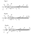
- FIG. 5 is a schematic diagram illustrating a longitudinal section of a fiber amplifier comprising an optical pumping device according to a second embodiment of the present invention.
- FIGS. 6A and 6B are schematic diagrams illustrating fiber lasers equipped with optical pumping devices according to the present invention.
- FIG. 7 is a schematic diagram illustrating a short fiber amplifier in which a large core double cladding fiber is coupled to an optical pumping device.
- FIG. 8 is a schematic diagram illustrating a longitudinal section of a fiber amplifier having a diode bar as a pump light source.
- FIG. 9 is a schematic diagram illustrating a longitudinal section of a tapered light guiding fiber and an amplifier fiber in which the taper is formed using a heating and pulling technique.
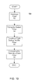
- FIG. 10 is a flowchart of a method for fabricating the tapered light guiding fiber of FIG. 9.
- FIG. 11 is a schematic diagram illustrating a method for fabricating a light guiding section as shown in FIGs. 1 to 8.
- FIG. 1 shows a fiber amplifier comprising an optical pump device according to a first preferred embodiment of the present invention. It comprises a light guiding section 1 formed of a single mode fiber pigtail, a broad stripe pump laser diode 5 as a light source, and a double cladding gain fiber 6.
- the light guiding section 1 is made from a fiber having a jacket 8, a cladding 9 inside the jacket and a single mode undoped core 10 at the center of the cladding.
- the undoped core can be single-mode or multimode.
- this fiber structure is left intact.
- the jacket 8 is removed, so as to expose the cladding 9, and a v-shaped groove 12 is formed at one side of the cladding 9.
- a narrow diameter portion 4 at the narrow end of tapered portion 3 is connected, for example by fusion splicing, to double cladding gain fiber 6.
- Gain fiber 6 has a doped core 13 surrounded by inner and outer claddings 14, 15.
- Outer cladding 15 may be e.g. a polymer, vacuum or a gas.
- Doped core 13, just like undoped core 10, can be single-mode oder multimode.
- the light guiding section 1 and the gain fiber 6 may be constructed from one fiber.
- the diameter of the cores 10, 13 of the light guiding section land the gain fiber 6 are identical, and so are the outer diameters of narrow portion 4 and of inner cladding 14 of the gain fiber 6.
- the light guiding section 1 may be formed from a piece of optical fiber for example, by a chemical etching, laser ablation technique or other methods.
- an end portion of a piece of fiber having its jacket removed may be suspended in an etching solution, the solution initially covering what is to become the tapered and narrow diameter portions 3, 4 of light guiding section 1.
- the fiber is then gradually raised out of the etching solution, so that the total exposure time to the etching solution will increase as the end of the fiber is approached. By controlling the raising speed, the angle of taper may be defined.
- solutions of hydrofluoric acid are applicable.
- portions 2 and 4 are shown to have a finite length with a constant diameter. However, the length of these portions might be reduced to 0.
- the wide diameter portion 2 in which the v-shaped groove 12 is formed might be tapered just like tapered portion 3.
- Pump light is generated by a broad area laser diode 5.
- diodes typically have an emission region of 1x100 ⁇ m, but diodes with an emitter width of up to 500 ⁇ m are available and can be used.
- the longer one of the two dimensions of the emission region is parallel to a plane of a diode junction, whereas the shorter one is in a plane perpendicular to the junction.
- the emission In the plane perpendicular to the diode junction the emission, confined to approximately 1 ⁇ m at the diode facet, is diffraction limited and diverges with a large angle, equivalent to a first numerical aperture of typically 0.5.
- the emission at the diode facet is 100 ⁇ m wide, is spatially incoherent, and diverges at a relatively small angle equivalent to a third numerical aperture of 0.1.
- an optical system 17 is provided in order to efficiently collect the light from the laser diode 5, reduce its divergence angle and focus it onto a facet 18 of the v-shaped groove 12 with a second and fourth numerical apertures.
- These various numerical apertures are designated as NA1, NA2, NA3, and NA4 in Figs 1 and 2.
- the v-shaped groove 12 has an orientation perpendicular to the longitudinal access of the light guiding section, its facets are at right angles (90°) with respect to each other, and, in particular, its facet 18 has an angle of 45° with respect to the core, so that pump light incident from the laser diode 5 at a right angle with respect to the core will be reflected essentially parallel to the core towards tapered portion 3.
- Reflection may be achieved by total internal reflection at the facet 18, or a reflective coating may be formed on facet 18.
- the function of the tapered portion 3 is to reduce the diameter of cladding 9 by a fixed ratio, while preserving the brightness of the pump light in the tapered portion 3.
- Since the numerical aperture of the double inner cladding 14 of cladding gain fiber 6 is typically limited to 0.4-0.6, to assure that light in the narrow end of the taper is within this range, the input beam has to have as small a numerical aperture as possible.
- a pump beam with a numerical aperture of 0.1 or less is coupled into the wide diameter portion 2 of the light guiding section 1, allowing a taper reduction factor of between 2 to 6.
- Another advantage of the present invention is that it allows the pump coupling to be carried out in the wide diameter section 2 of the fiber instead of a small diameter fiber.
- the large fiber diameter of the wide diameter section 2 makes it possible to fabricate a v-groove with a large depth and width so that the spot of light formed by the focused laser diode 5 light is intercepted by a relatively large v-groove facet. This large facet area results in a diode-lens-v-groove alignment tolerance increase, approximately equal to the ratio of the wide diameter section 2 to the small diameter fiber diameter.
- v-groove depth is approximately 16 micrometers.
- Such a small v-groove depth would require a very tight alignment tolerance, only a factor of two better than that associated with single mode fiber pigtailing.
- a similar fiber with a 125 micrometers cladding in the wide diameter section 2 would allow a v-groove depth of 53 micrometers, a 3-fold improvement over the small diameter fiber case and an improvement of approximately 7-fold over single mode fiber pigtailing. This permits the construction of an environmentally insensitive fiber amplifier or laser.
- optical systems for achieving the collection and beam conditioning functions described can be used, such as combinations of spherical and cylindrical lenses, or a micro-lens in which the front and back surfaces constitute crossed cylindrical lenses.
- the pump light After coupling into the light guiding section 1 at the wide diameter portion 2, the pump light propagates into tapered portion 3 as shown in FIG. 3.
- the reduction of the cladding diameter has to take place slowly, typically over a distance of approximately 100 times the fiber diameter of wide portion 2.
- a shorter distance may be used for smaller taper reduction factors (e.g. , 50 times the fiber diameter of the wide portion).
- a low refractive index material that may constitute an outer cladding of light guiding section 1 surrounds the tapered portion 3.
- the tapered portion functions as a double cladding fiber with the pump light confined in the inner cladding surrounding 9 the core.
- a low refractive index outer cladding is a polymer, but air can also constitute such an outer cladding.
- the narrow diameter portion 4 of light guiding section 1 may be coupled to the double cladding gain fiber 6 by a fusion splice 22.
- the mode field diameters of the doped core 13 of double cladding gain fiber 6 and the core 10 of light guiding section 1 should be equal, and so should the diameter of cladding 9 at the narrow diameter portion 4 and inner cladding 14 of gain fiber 6.
- the far end of double cladding gain fiber 6 can be fusion spliced to a second single mode fiber pigtail to remove the residual pump light in the cladding 14.
- a second pumping device similar to that of FIG. 1 may be coupled to the far end of gain fiber 6 by a second fusion splice 22'.
- Such an arrangement results in doubling the amount of pump power that can be coupled into the gain fiber 6, making possible a significant increase in amplifier outlet power and population inversion.
- FIG. 4B Further scaling of the fiber amplifier can be achieved through the use of multiple pumping devices 25, 25', 25" located at terminal and intermediate positions of the fiber amplifier and connected in series, as shown in FIG. 4B.
- the pumping devices 25, 25', 25" are separated by sufficient lengths of gain fiber 6 to absorb the pump light from one device before it can reach the v-groove 12 of the next device.
- all laser diodes are shown to illuminate the same facet (the right hand facet) of the respective light guiding portions 1, so that the pump light will always all be either co-propagating or counter-propagating with respect to light to be amplified in the fiber core.
- the optical system 17 might be arranged so as to focus the light from the laser diode 5 onto the edge between the two facets of its respective groove, or a beam splitter might be provided for directing two beams on the two facets, in order to distribute the light from the laser diode 5 between the two neighboring lengths of gain fiber 6.
- FIG. 5 Another alternative amplifier configuration is shown in FIG. 5.
- the pump light is coupled into an end surface 30 of the pigtail fiber, as shown.
- the pigtail fiber in which the light guiding portion 1 is formed is also of a double cladding structure. This is required to allow pump light which is coupled into the inner cladding 9 of the pigtail to propagate without significant attenuation to the tapered portion located in the same fiber.
- a dichroic beam splitter 31 is interposed between the pump diode 5 and its optical system 17 on the one hand and the end face 30, on the other.
- This beam splitter 31 is for coupling signal light to be amplified into or amplified light out of the core 10 of the fiber pigtail 32.
- the beam splitter 31 is highly reflective at the signal wavelength and highly transmissive at the pump wavelength.
- the end face 30 of fiber pigtail 32 can be antireflection coated at both wavelengths.
- the end face 30 can be fabricated at a small angle relative to the axis of the fiber pigtail 32.
- the optical pumping device of the present invention can also be used to construct a fiber laser.
- An end pumped fiber laser comprising the end-pumping device of Fig 5 is shown in FIG. 6A.
- the end face 30 of fiber pigtail 32 is coated to have high reflectivity at the lasing wavelength of doped core 13 of the gain fiber 6 and high transmission at the pump wavelength.
- a reflector 33 at the far end of gain fiber 6 completes the fiber laser cavity.
- the reflector 33 can be highly reflective at the pump wavelength and partially reflective at the lasing wavelength.
- a fiber laser can also be made using a Bragg fiber grating in an arrangement shown in FIG. 6B.
- the end face 30 of the fiber pigtail 32 is antireflection coated at the pump wavelength, and the laser mirror is in the form of a fiber grating 35 written into the core 10 of the pigtail fiber.
- the v-groove pumping device of FIGS. 1 to 4B may also be employed for pumping a fiber laser.
- a reflector at end face 30 of fiber pigtail 32 may be fully reflecting at the wavelength of the pump light, too.
- the Er transition is almost entirely 3-level for wavelengths in the 1480-1530 nm range, which are of great interest for short band fiber communication systems.
- the Yb transition is almost entirely 3-level for wavelength in the 975-1020 nm range, which are of great interest for pumping of fiber amplifiers and sensing applications.
- the shortest wavelength for getting significant gain is approximately 1530 nm, while the shortest wavelength for conventional Yb doped double cladding fibers is approximately 1020nm.
- amplification in double cladding gain fibers at wavelengths substantially shorter than these values is possible.
- Other types of commonly used fiber amplifiers which will also benefit from this invention, are based on Nd-doped silica and Tm-doped silica.
- An advantage of this invention is that it allows very short amplifiers to be constructed using core dopants that can be used with high concentrations, such as Yb, Er/Yb, Nd, and Tm.
- core dopants such as Yb, Er/Yb, Nd, and Tm.
- Yb for example, very high concentrations, corresponding in core absorption coefficients of 1000-2000 dB/m can be used.
- this translates into a cladding absorption of 40-80 dB/m, making it possible to build high efficiency fiber amplifiers and lasers as short as 12.5-25 cm (90% pump absorption).
- Such fiber lasers are required to achieve single mode longitudinal mode emission.
- Very short fiber amplifiers because of reduction of nonlinear effects in the fiber core, can be used to generate very high peak power pulses.
- gain fibers having much smaller area ratios than those mentioned above, e.g., with larger core diameters of the gain fiber, can be used so that even shorter amplifiers can be constructed.
- Such fibers will allow construction of efficient amplifiers with a length of only 2-4 cm.
- the single mode seed signal can be provided through the use of a pumping device with a single mode core 10, which is directly spliced to a multi-mode core 13' of a double cladding gain fiber 6' as shown in FIG. 7.
- the cores 10, 13' can be tapered during the fusion splicing process.
- the core 10 in the pumping device can be the same size as the large multimode core 13' in the double cladding gain fiber 6.
- a fiber coupled laser diode bar might be used as a light source of a pumping device for pumping a double cladding gain fiber.
- fiber coupled bars can deliver power of up to 40 W in a 200 ⁇ m diameter fiber with a NA of 0.22.
- pump light from a fiber 37 coupled bar 36 can be injected into the inner core 10 of a pumping device using a v-groove 12, or by using an end coupling arrangement similar to that of FIG. 5.
- various optical elements such as lenses can be interposed between the end of the pump fiber 37 and the wide diameter portion 2 with the v-groove 12.
- a taper reduction ratio of 2.5 would allow the power from pump fiber 37 to be efficiently coupled into a 180 ⁇ m diameter, 0.55 NA double cladding gain fiber 6, resulting in a pump intensity which is comparable to that achieved with a single 4 W broad stripe laser diode coupled into a double cladding gain fiber 6 with a diameter of 57 ⁇ m.
- the 450 ⁇ m diameter of the wide diameter portion 2 of the light guiding section 1 allows a v-groove depth and half-width of approximately 215 ⁇ m, which is sufficiently large to allow a small amount of diffractive spreading of the pump light as it travels from the end of the pump fiber 37 to the surface of v-groove 12, as shown in FIG. 8. Because of the relatively large 0.22 numerical aperture of the pump light incident on the v-groove facet surface, total internal reflection at the facet surface will not provide sufficiently large angular coverage, and a high reflectivity coating with a large angular acceptance range might be required to be deposited on the v-groove surface.
- One of the advantages of the fiber coupled source is that the available power is approximately 10 times greater than that from a single broad stripe laser diode, another is that the pump source is remotely located from the gain fiber 6.
- the advantages of the invention include providing a means for achieving a high pump power density in double cladding gain fibers.
- Using the pumping device of the invention it is possible to construct high power amplifiers at 1.5 ⁇ m using Er doping rather than Er/Yb co-doping, allowing a flatter gain distribution required for WDM systems and other applications.
- the invention also makes it possible to construct such amplifiers using a v-groove side-pumping technique with a large misalignment tolerance, provides access to ends of the double cladding fiber so that conventional single mode fiber pigtails can be fusion spliced to the ends.
- Alternative pumping schemes can use bulk lenses to achieve pump beam reduction that is obtained through the use of the tapered fiber region described above. Coupling of the pump light can be achieved through the end of the double cladding fiber using dichroic beam-splitters to combine the pump light with the signal light.
- the tapered and narrow portions of the light guiding section may be fabricated by chemical etching or laser ablation of the fiber surface.
- An advantage of these methods of taper fabrication are that the diameter of the single mode core remains constant throughout the taper allowing the narrow end to be fusion spliced to a double cladding doped fiber with a matching core and mode field diameters.
- a disadvantage of these methods is that material removal from the fiber surface can produce surface roughness that can scatter the pump light, resulting in a decrease in amplifier efficiency.
- an alternative method of achieving the tapering described herein and fabricating the tapered portion 3' and narrow portion 4' of the light guiding section 1' includes a heating and pulling technique.
- an optical pumping device 40 e.g. an amplifier
- a light guiding section 1' made by the heating and pulling technique is shown.
- the method 50 preferably comprises heating 52 a fiber (preferably a single mode fiber 42 with an undoped core 10'), pulling 54 the heated single mode fiber 42 until the desired tapered portion 3' and a narrow portion 4' of the desired length are achieved, coupling 56 ( e.g., via a v-groove 12 fabricated in the fiber 42) a light source (e.g., a broad stripe laser diode 5) into the tapered single mode fiber 42, and connecting 58 ( e.g ., by fusion splicing) the tapered single mode fiber 42 to a double cladding gain fiber 6.
- a fiber preferably a single mode fiber 42 with an undoped core 10'
- pulling 54 the heated single mode fiber 42 until the desired tapered portion 3' and a narrow portion 4' of the desired length are achieved
- coupling 56 e.g., via a v-groove 12 fabricated in the fiber 42
- a light source e.g., a broad stripe laser diode 5
- the fiber 42 of the light guiding section 1' is heated to the softening point of silica and pulled to create the tapered portion 3' and the narrow portion 4'.
- the heating step 52 may be accomplished through a variety of means, including flame torch, CO 2 laser, an electric arc or resistive heating.
- the tapered light guiding section 1' should include a constant diameter wide portion 2', a tapered portion 3', and a fixed diameter narrow portion 4'.
- the constant diameter portions 2' and 4' allow the tapered light guiding section 1' to be cleaved and fusion spliced (or otherwise connected) to fibers (e.g., double cladding gain fiber 6) with matching diameters.
- the heating-and-pulling technique reduces the single mode core 10' diameter by the same ratio as the reduction in the outer fiber 42 diameter.
- a tapered portion 3' constructed in this manner minimizes the pump light and signal light coupling losses into the double cladding fiber 6.
- the mode field radii w o of the light guiding section 1' and the doped double cladding fiber 6 might differ.
- the taper of the tapered portion 3' can be used to adiabatically increase or decrease the mode size so that it matches the mode of the doped double cladding fiber 6.
- a fiber 60 (preferably a single mode fiber 42 with an undoped core 10) is rotated, around an axis defined by the fiber's 60 core (not shown in FIG. 11) and bent so that the fiber 60 contacts a polishing disc 62 at an angle.
- the polishing disc 62 is preferably rotating.
- the bend 64 in the fiber 60 causes a variation in the contact pressure of the fiber 60 with the polishing disc 62.
- the variation in the contact pressure results in a different rate of glass removal (i.e ., of the cladding) of the fiber 60 along the length of the fiber 60, resulting in tapering from a wide portion (not shown in FIG.
- the length and ratio of the taper may be adjusted by varying the radius of the bend 64, the polishing time and/or the rotation rates of the polishing disc 64 and the fiber 60.
- a method using the polishing technique described herein is similar to the method 50 shown in FIG. 10, with the heating 52 and pulling 54 steps replaced by steps of bending the fiber 60 and polishing the fiber 60.
Landscapes
- Physics & Mathematics (AREA)
- Electromagnetism (AREA)
- Engineering & Computer Science (AREA)
- Plasma & Fusion (AREA)
- Optics & Photonics (AREA)
- Lasers (AREA)
Applications Claiming Priority (2)
| Application Number | Priority Date | Filing Date | Title |
|---|---|---|---|
| US09/722,271 US6608951B1 (en) | 2000-11-28 | 2000-11-28 | Optical fiber amplifiers and lasers and optical pumping device therefor |
| US722271 | 2000-11-28 |
Publications (2)
| Publication Number | Publication Date |
|---|---|
| EP1213802A2 true EP1213802A2 (fr) | 2002-06-12 |
| EP1213802A3 EP1213802A3 (fr) | 2004-11-03 |
Family
ID=24901142
Family Applications (1)
| Application Number | Title | Priority Date | Filing Date |
|---|---|---|---|
| EP01128123A Withdrawn EP1213802A3 (fr) | 2000-11-28 | 2001-11-27 | Lasers et amplificateurs à fibres optiques et leur dispositif de pompage et procédés de fabrication |
Country Status (2)
| Country | Link |
|---|---|
| US (2) | US6608951B1 (fr) |
| EP (1) | EP1213802A3 (fr) |
Cited By (5)
| Publication number | Priority date | Publication date | Assignee | Title |
|---|---|---|---|---|
| WO2005002005A2 (fr) | 2003-05-30 | 2005-01-06 | Bae Systems Information And Electronic Systems Integration Inc. | Procede et dispositif de pompage lateral par emetteurs multiples pour lasers a fibres optiques |
| US7038844B2 (en) | 2003-09-29 | 2006-05-02 | The Regents Of The University Of California | High power 938 nanometer fiber laser and amplifier |
| US7161966B2 (en) | 2003-01-24 | 2007-01-09 | Trumpf, Inc. | Side-pumped fiber laser |
| US7542488B2 (en) | 2003-01-24 | 2009-06-02 | Trumpf, Inc. | Fiber laser |
| CN103606805A (zh) * | 2013-10-22 | 2014-02-26 | 长春理工大学 | 双包层光纤激光器的包层光滤除装置及制法 |
Families Citing this family (69)
| Publication number | Priority date | Publication date | Assignee | Title |
|---|---|---|---|---|
| US7269219B1 (en) * | 1997-02-14 | 2007-09-11 | At&T Corp. | Non-linear quantizer for video coding |
| DE19723267A1 (de) * | 1997-06-03 | 1998-12-10 | Heidelberger Druckmasch Ag | Verfahren und Anordnung zur Reduzierung des Pumplichts am Austritt eines Fiberlasers |
| JP4372330B2 (ja) * | 2000-10-30 | 2009-11-25 | 富士通株式会社 | 分布型光増幅装置、光通信用の局および光通信システム |
| US20020168139A1 (en) * | 2001-03-30 | 2002-11-14 | Clarkson William Andrew | Optical fiber terminations, optical couplers and optical coupling methods |
| US6717720B2 (en) * | 2001-06-06 | 2004-04-06 | Keopsys, Inc. | Hermetic pump module for double cladding fiber amplifiers and method for making same |
| KR100458678B1 (ko) * | 2002-03-20 | 2004-12-03 | 주식회사 럭스퍼트 | 이득제공 방식의 광파워 평탄화기 |
| US6960035B2 (en) * | 2002-04-10 | 2005-11-01 | Fuji Photo Film Co., Ltd. | Laser apparatus, exposure head, exposure apparatus, and optical fiber connection method |
| RU2229770C2 (ru) * | 2002-07-12 | 2004-05-27 | Научный центр волоконной оптики при Институте общей физики РАН | Устройство для защиты волоконных линий от разрушения под действием лазерного излучения |
| JP2004145212A (ja) * | 2002-10-28 | 2004-05-20 | Shinko Electric Ind Co Ltd | テープファイバおよび光ファイバの加工方法 |
| US6842570B2 (en) * | 2002-12-11 | 2005-01-11 | Northrop Grumman Corporation | Method for coupling diode array light into an optical fiber |
| US9022037B2 (en) | 2003-08-11 | 2015-05-05 | Raydiance, Inc. | Laser ablation method and apparatus having a feedback loop and control unit |
| US7233724B2 (en) * | 2003-11-20 | 2007-06-19 | Northrop Grumman Corporation | Long period bragg grating optical signal attenuation |
| US7557986B2 (en) * | 2004-05-13 | 2009-07-07 | Soreq Nuclear Research Center | High power fiber amplifier |
| US7099074B2 (en) * | 2004-11-30 | 2006-08-29 | The Aerospace Corporation | Side-pumping laser and optical fiber system |
| US7526003B2 (en) * | 2004-12-08 | 2009-04-28 | Polaronyx, Inc. | Nonlinear polarization pulse shaping mode locked fiber laser at one micron |
| JP2006261194A (ja) * | 2005-03-15 | 2006-09-28 | Jtekt Corp | ファイバレーザ発振器 |
| US7477666B2 (en) * | 2005-04-06 | 2009-01-13 | Polar Onyx, Inc. | All fiber based short pulse amplification at one micron |
| US7529278B2 (en) * | 2005-05-23 | 2009-05-05 | Polaronyx, Inc. | Nonlinear polarization pulse shaping model locked fiber laser at one micron with photonic crystal (PC), photonic bandgap (PBG), or higher order mode (HOM) fiber |
| US7391561B2 (en) * | 2005-07-29 | 2008-06-24 | Aculight Corporation | Fiber- or rod-based optical source featuring a large-core, rare-earth-doped photonic-crystal device for generation of high-power pulsed radiation and method |
| US7400807B2 (en) * | 2005-11-03 | 2008-07-15 | Aculight Corporation | Apparatus and method for a waveguide with an index profile manifesting a central dip for better energy extraction |
| US11324553B2 (en) * | 2005-11-10 | 2022-05-10 | Biolitec Unternehmensbeteilgungs II AG | Side fire optical fiber for high power applications |
| US7570856B1 (en) | 2005-12-07 | 2009-08-04 | Lockheed Martin Corporation | Apparatus and method for an erbium-doped fiber for high peak-power applications |
| US8232687B2 (en) | 2006-04-26 | 2012-07-31 | Raydiance, Inc. | Intelligent laser interlock system |
| US9130344B2 (en) | 2006-01-23 | 2015-09-08 | Raydiance, Inc. | Automated laser tuning |
| JP4796950B2 (ja) * | 2006-02-03 | 2011-10-19 | 日本碍子株式会社 | 光デバイス |
| JP4796951B2 (ja) * | 2006-02-03 | 2011-10-19 | 日本碍子株式会社 | 光デバイス |
| JP2009528128A (ja) * | 2006-03-03 | 2009-08-06 | ユニヴァーシティ オブ ワシントン | 多クラッド光ファイバ走査器 |
| US7532792B2 (en) * | 2006-08-28 | 2009-05-12 | Crystal Fibre A/S | Optical coupler, a method of its fabrication and use |
| EP2016652B1 (fr) | 2006-05-11 | 2014-06-18 | SPI Lasers UK Limited | Appareil de rayonnement optique |
| US7289707B1 (en) * | 2006-05-12 | 2007-10-30 | Np Photonics, Inc | Multi-core optical fiber image amplifier and method of drawing |
| US7768700B1 (en) | 2006-11-30 | 2010-08-03 | Lockheed Martin Corporation | Method and apparatus for optical gain fiber having segments of differing core sizes |
| KR100799576B1 (ko) | 2006-08-18 | 2008-01-30 | 한국전자통신연구원 | 광신호 아웃-커플링 광섬유 및 그 광섬유를 이용한 광신호검출장치 |
| KR100860405B1 (ko) | 2006-11-15 | 2008-09-26 | 한국전자통신연구원 | 광섬유 일체형 파장분할다중화 장치 및 그 장치에서의다채널 광신호 방출 방법 |
| US7539377B2 (en) * | 2007-01-11 | 2009-05-26 | Gonthier Francois | Method and device for optically coupling optical fibres |
| US7916386B2 (en) * | 2007-01-26 | 2011-03-29 | Ofs Fitel, Llc | High power optical apparatus employing large-mode-area, multimode, gain-producing optical fibers |
| US7437046B2 (en) * | 2007-02-12 | 2008-10-14 | Furukawa Electric North America, Inc. | Optical fiber configuration for dissipating stray light |
| CA2683951C (fr) * | 2007-04-18 | 2016-09-27 | Francois Gonthier | Amplificateur de fibre optique |
| US20080267560A1 (en) * | 2007-04-30 | 2008-10-30 | Digiovanni David John | Mode-field resizing in optical fibers |
| JP5124225B2 (ja) * | 2007-05-15 | 2013-01-23 | 株式会社フジクラ | 光ファイバ融着接続構造 |
| WO2009043964A1 (fr) * | 2007-10-03 | 2009-04-09 | Optoelectronics Research Centre, Tampere University Of Technology | Fibre optique active et son procédé de fabrication |
| US9063289B1 (en) | 2008-06-30 | 2015-06-23 | Nlight Photonics Corporation | Multimode fiber combiners |
| US9285541B2 (en) | 2008-08-21 | 2016-03-15 | Nlight Photonics Corporation | UV-green converting fiber laser using active tapers |
| US9158070B2 (en) | 2008-08-21 | 2015-10-13 | Nlight Photonics Corporation | Active tapers with reduced nonlinearity |
| US8873134B2 (en) | 2008-08-21 | 2014-10-28 | Nlight Photonics Corporation | Hybrid laser amplifier system including active taper |
| US20110146071A1 (en) * | 2008-10-06 | 2011-06-23 | Afl Telecommunications Llc | Thermal rounding shaped optical fiber for cleaving and splicing |
| US8070341B2 (en) * | 2008-12-18 | 2011-12-06 | Visteon Global Technologies, Inc. | Light pipe with uniformly lit appearance |
| US9494738B1 (en) | 2009-05-28 | 2016-11-15 | Nlight, Inc. | Single mode fiber combiners |
| US8818151B1 (en) * | 2009-08-03 | 2014-08-26 | United States Of America As Represented By The Secretary Of The Air Force | Fiber Pump Signal Combiner |
| JP2011123398A (ja) * | 2009-12-14 | 2011-06-23 | Hitachi Cable Ltd | 光ファイバおよびその製造方法、並びに光ファイバの端部加工方法 |
| KR20110068492A (ko) * | 2009-12-16 | 2011-06-22 | 한국전자통신연구원 | 광 결합장치 및 그를 구비한 능동 광모듈 |
| WO2011088569A1 (fr) | 2010-01-22 | 2011-07-28 | Genia Photonics Inc. | Procédé et dispositif pour coupler optiquement des fibres optiques |
| JP2011203544A (ja) * | 2010-03-26 | 2011-10-13 | Fujikura Ltd | 光ファイバの接続方法、及び、光ファイバの接続構造 |
| US8363310B2 (en) * | 2010-05-04 | 2013-01-29 | The United States Of America As Represented By The Secretary Of The Army | High power and high gain fiber amplifier |
| US8735791B2 (en) | 2010-07-13 | 2014-05-27 | Svv Technology Innovations, Inc. | Light harvesting system employing microstructures for efficient light trapping |
| US8908263B2 (en) * | 2011-06-17 | 2014-12-09 | Jds Uniphase Corporation | Large mode area optical waveguide devices |
| US10239160B2 (en) | 2011-09-21 | 2019-03-26 | Coherent, Inc. | Systems and processes that singulate materials |
| CN103858293B (zh) * | 2012-01-20 | 2018-01-02 | Ipg光子公司 | 利用单模钕光纤泵浦源的高功率单模镱光纤激光器系统 |
| US9484706B1 (en) | 2012-06-12 | 2016-11-01 | Nlight, Inc. | Tapered core fiber manufacturing methods |
| US9147992B2 (en) * | 2012-11-09 | 2015-09-29 | Coherent, Inc. | High efficiency amplification of pulsed laser output for high energy ultrafast laser systems |
| US20150277065A1 (en) * | 2012-11-26 | 2015-10-01 | Shalom Wertsberger | Optical fiber source and repeaters using tapered core waveguides |
| WO2014105756A1 (fr) | 2012-12-31 | 2014-07-03 | Nlight Photonics Corporation | Fibre à brillance élevée stable dans l'espace |
| WO2014105757A1 (fr) | 2012-12-31 | 2014-07-03 | Nlight Photonics Corporation | Amplificateur à fibres lma tout en fibres à faible pointage dynamique de forte puissance |
| US9214781B2 (en) | 2013-11-21 | 2015-12-15 | Lockheed Martin Corporation | Fiber amplifier system for suppression of modal instabilities and method |
| CN103777271A (zh) * | 2013-11-27 | 2014-05-07 | 清华大学 | 光纤、光纤振荡器和光纤放大器 |
| US9917411B2 (en) * | 2015-06-25 | 2018-03-13 | Optical Engines, Inc. | Double fiber optic mode adapter |
| JP6965758B2 (ja) * | 2018-01-10 | 2021-11-10 | 住友電気工業株式会社 | 光モジュール |
| US11808970B2 (en) | 2019-01-02 | 2023-11-07 | Lumentum Operations Llc | Optical fiber with variable absorption |
| US11175449B2 (en) * | 2019-01-02 | 2021-11-16 | Lumentum Operations Llc | Optical fiber with variable absorption |
| CN111676532B (zh) * | 2020-06-10 | 2022-03-01 | 华中科技大学 | 一种发光纤维、及其制备方法和应用、发光口罩 |
Citations (5)
| Publication number | Priority date | Publication date | Assignee | Title |
|---|---|---|---|---|
| EP0138411A2 (fr) * | 1983-09-30 | 1985-04-24 | The Board Of Trustees Of The Leland Stanford Junior University | Amplificateur à fibre optique |
| US4900114A (en) * | 1986-02-14 | 1990-02-13 | British Telecommunications, Plc. | Technique for reducing fibre joint loss |
| US5854865A (en) * | 1995-12-07 | 1998-12-29 | The United States Of America As Represented By The Secretary Of The Navy | Method and apparatus for side pumping an optical fiber |
| US5864644A (en) * | 1997-07-21 | 1999-01-26 | Lucent Technologies Inc. | Tapered fiber bundles for coupling light into and out of cladding-pumped fiber devices |
| US5877890A (en) * | 1996-10-30 | 1999-03-02 | Rutgers, The State University Of New Jersey | Optical-fiber amplifier having high-saturation output |
Family Cites Families (10)
| Publication number | Priority date | Publication date | Assignee | Title |
|---|---|---|---|---|
| US5048026A (en) * | 1983-09-30 | 1991-09-10 | The Board Of Trustees Of The Leland Stanford Junior University | Fiber optic amplifier |
| US4737004A (en) * | 1985-10-03 | 1988-04-12 | American Telephone And Telegraph Company, At&T Bell Laboratories | Expanded end optical fiber and associated coupling arrangements |
| US4815079A (en) | 1987-12-17 | 1989-03-21 | Polaroid Corporation | Optical fiber lasers and amplifiers |
| US5037172A (en) * | 1989-03-22 | 1991-08-06 | Teledyne Industry, Inc. | Fiber optic device with a reflective notch coupler |
| US5432876C1 (en) * | 1992-10-19 | 2002-05-21 | Minnesota Mining & Mfg | Illumination devices and optical fibres for use therein |
| US6072811A (en) * | 1998-02-11 | 2000-06-06 | Imra America | Integrated passively modelocked fiber lasers and method for constructing the same |
| US6525872B1 (en) * | 1999-02-11 | 2003-02-25 | Jds Uniphase Corporation | Fiber grating-stabilized, semiconductor pump source |
| US6324326B1 (en) * | 1999-08-20 | 2001-11-27 | Corning Incorporated | Tapered fiber laser |
| US6543942B1 (en) * | 2000-09-21 | 2003-04-08 | Fitel Usa Corp. | Dispersion-compensating fiber system having a bridge fiber and methods for making same |
| WO2002042803A2 (fr) * | 2000-11-27 | 2002-05-30 | Northstar Photonics, Inc. | Dispositif et procede pour composants photoniques integres |
-
2000
- 2000-11-28 US US09/722,271 patent/US6608951B1/en not_active Expired - Fee Related
-
2001
- 2001-11-27 EP EP01128123A patent/EP1213802A3/fr not_active Withdrawn
- 2001-12-14 US US10/014,467 patent/US6731837B2/en not_active Expired - Fee Related
Patent Citations (5)
| Publication number | Priority date | Publication date | Assignee | Title |
|---|---|---|---|---|
| EP0138411A2 (fr) * | 1983-09-30 | 1985-04-24 | The Board Of Trustees Of The Leland Stanford Junior University | Amplificateur à fibre optique |
| US4900114A (en) * | 1986-02-14 | 1990-02-13 | British Telecommunications, Plc. | Technique for reducing fibre joint loss |
| US5854865A (en) * | 1995-12-07 | 1998-12-29 | The United States Of America As Represented By The Secretary Of The Navy | Method and apparatus for side pumping an optical fiber |
| US5877890A (en) * | 1996-10-30 | 1999-03-02 | Rutgers, The State University Of New Jersey | Optical-fiber amplifier having high-saturation output |
| US5864644A (en) * | 1997-07-21 | 1999-01-26 | Lucent Technologies Inc. | Tapered fiber bundles for coupling light into and out of cladding-pumped fiber devices |
Non-Patent Citations (3)
| Title |
|---|
| GOLDBERG L ET AL: "High-efficiency side-coupling of light into double-cladding fibers using imbedded v-grooves" TECHNICAL DIGEST OFC'96, 25 February 1996 (1996-02-25), pages 91-92, XP010539840 * |
| JEONG H ET AL: "Enhancement of butt-coupling pump efficiency in a new nd-doped large core double clad fiber laser cavity adiabatically tapered at both ends" CONFERENCE ON LASERS AND ELECTRO-OPTICS. (CLEO 2001). TECHNICAL DIGEST. POSTCONFERENCE EDITION. BALTIMORE, MD, MAY 6-11, 2001, TRENDS IN OPTICS AND PHOTONICS. (TOPS), US, WASHINGTON, WA : OSA, US, vol. VOL. 56, 6 May 2001 (2001-05-06), pages 320-320, XP010559890 ISBN: 1-55752-662-1 * |
| PATENT ABSTRACTS OF JAPAN vol. 0161, no. 23 (P-1330), 27 March 1992 (1992-03-27) & JP 3 289633 A (SUMITOMO ELECTRIC IND LTD; others: 01), 19 December 1991 (1991-12-19) * |
Cited By (7)
| Publication number | Priority date | Publication date | Assignee | Title |
|---|---|---|---|---|
| US7161966B2 (en) | 2003-01-24 | 2007-01-09 | Trumpf, Inc. | Side-pumped fiber laser |
| US7542488B2 (en) | 2003-01-24 | 2009-06-02 | Trumpf, Inc. | Fiber laser |
| WO2005002005A2 (fr) | 2003-05-30 | 2005-01-06 | Bae Systems Information And Electronic Systems Integration Inc. | Procede et dispositif de pompage lateral par emetteurs multiples pour lasers a fibres optiques |
| EP1636883A2 (fr) * | 2003-05-30 | 2006-03-22 | BAE Systems Information and Electronic Systems Integration Inc. | Procede et dispositif de pompage lateral par emetteurs multiples pour lasers a fibres optiques |
| EP1636883A4 (fr) * | 2003-05-30 | 2007-07-04 | Bae Systems Information | Procede et dispositif de pompage lateral par emetteurs multiples pour lasers a fibres optiques |
| US7038844B2 (en) | 2003-09-29 | 2006-05-02 | The Regents Of The University Of California | High power 938 nanometer fiber laser and amplifier |
| CN103606805A (zh) * | 2013-10-22 | 2014-02-26 | 长春理工大学 | 双包层光纤激光器的包层光滤除装置及制法 |
Also Published As
| Publication number | Publication date |
|---|---|
| US6608951B1 (en) | 2003-08-19 |
| US20020094159A1 (en) | 2002-07-18 |
| EP1213802A3 (fr) | 2004-11-03 |
| US6731837B2 (en) | 2004-05-04 |
Similar Documents
| Publication | Publication Date | Title |
|---|---|---|
| US6731837B2 (en) | Optical fiber amplifiers and lasers and optical pumping devices therefor and methods of fabricating same | |
| US5790722A (en) | High power optical fiber amplifier/laser system | |
| US6370180B2 (en) | Semiconductor-solid state laser optical waveguide pump | |
| EP0991967B1 (fr) | Fibre optique monomode | |
| EP2086069B1 (fr) | Dispositifs de gain à fibre optique pompée par la gaîne | |
| US6751241B2 (en) | Multimode fiber laser gratings | |
| US6836607B2 (en) | Cladding-pumped 3-level fiber laser/amplifier | |
| US6831934B2 (en) | Cladding pumped fiber laser | |
| US5710786A (en) | Optical fibre laser pump source for fibre amplifiers | |
| US8094370B2 (en) | Cladding pumped fibre laser with a high degree of pump isolation | |
| US5283846A (en) | Optical isolator, optical circuit, and rare-earth-doped fiber optical amplifier | |
| US20080267227A1 (en) | Gain-clamped optical amplifier using double-clad fiber | |
| US6433927B1 (en) | Low cost amplifier using bulk optics | |
| US20030161357A1 (en) | Laser with internally coupled pump source | |
| US6574393B2 (en) | Compact optical fiber amplifier module | |
| WO2001067559A2 (fr) | Procede et appareil de pompage de fibres optiques | |
| Headley III et al. | Tapered fiber bundles for combining laser pumps | |
| JP3029303B2 (ja) | マルチファイバ光増幅器およびそれを用いた多心光ファイバの接続構造 | |
| Simonneau et al. | High-power air-clad photonic crystal fiber cladding-pumped EDFA for WDM applications in the C-band | |
| Seo et al. | Single Mode Laser Oscillation in an Nd‐Doped Large Core Double Clad Fiber Cavity with Concatenated Adiabatic Tapers | |
| Lawrence et al. | Versatile waveguide design for optical amplification |
Legal Events
| Date | Code | Title | Description |
|---|---|---|---|
| PUAI | Public reference made under article 153(3) epc to a published international application that has entered the european phase |
Free format text: ORIGINAL CODE: 0009012 |
|
| AK | Designated contracting states |
Kind code of ref document: A2 Designated state(s): AT BE CH CY DE DK ES FI FR GB GR IE IT LI LU MC NL PT SE TR |
|
| AX | Request for extension of the european patent |
Free format text: AL;LT;LV;MK;RO;SI |
|
| PUAL | Search report despatched |
Free format text: ORIGINAL CODE: 0009013 |
|
| AK | Designated contracting states |
Kind code of ref document: A3 Designated state(s): AT BE CH CY DE DK ES FI FR GB GR IE IT LI LU MC NL PT SE TR |
|
| AX | Request for extension of the european patent |
Extension state: AL LT LV MK RO SI |
|
| AKX | Designation fees paid | ||
| RAP1 | Party data changed (applicant data changed or rights of an application transferred) |
Owner name: KEOPSYS |
|
| REG | Reference to a national code |
Ref country code: DE Ref legal event code: 8566 |
|
| STAA | Information on the status of an ep patent application or granted ep patent |
Free format text: STATUS: THE APPLICATION IS DEEMED TO BE WITHDRAWN |
|
| 18D | Application deemed to be withdrawn |
Effective date: 20050504 |