EP1213558B1 - Method and device for simulating exploding projectiles - Google Patents
Method and device for simulating exploding projectiles Download PDFInfo
- Publication number
- EP1213558B1 EP1213558B1 EP01811099A EP01811099A EP1213558B1 EP 1213558 B1 EP1213558 B1 EP 1213558B1 EP 01811099 A EP01811099 A EP 01811099A EP 01811099 A EP01811099 A EP 01811099A EP 1213558 B1 EP1213558 B1 EP 1213558B1
- Authority
- EP
- European Patent Office
- Prior art keywords
- weapon
- signal
- transmitter
- sensor
- impact
- Prior art date
- Legal status (The legal status is an assumption and is not a legal conclusion. Google has not performed a legal analysis and makes no representation as to the accuracy of the status listed.)
- Expired - Lifetime
Links
Images

Classifications
-
- F—MECHANICAL ENGINEERING; LIGHTING; HEATING; WEAPONS; BLASTING
- F41—WEAPONS
- F41G—WEAPON SIGHTS; AIMING
- F41G3/00—Aiming or laying means
- F41G3/26—Teaching or practice apparatus for gun-aiming or gun-laying
- F41G3/2616—Teaching or practice apparatus for gun-aiming or gun-laying using a light emitting device
- F41G3/2622—Teaching or practice apparatus for gun-aiming or gun-laying using a light emitting device for simulating the firing of a gun or the trajectory of a projectile
-
- F—MECHANICAL ENGINEERING; LIGHTING; HEATING; WEAPONS; BLASTING
- F41—WEAPONS
- F41G—WEAPON SIGHTS; AIMING
- F41G3/00—Aiming or laying means
- F41G3/26—Teaching or practice apparatus for gun-aiming or gun-laying
Definitions
- the present invention relates to a method for Simulation of the effect of exploding projectiles according to The preamble of claim 1. Furthermore, the Invention on a device for carrying out the Process according to the preamble of the first Apparatus claim.
- a well-known kind of detonating projectiles are those of ballistic weapons (mortars, Guns) are fired. For the simulation will be off the gun alignment and other parameters the trajectory and the detonation point calculated. Because of the relative long flight time of several seconds, this calculation be performed by a central computer.
- DE 198 03 337 A1 discloses a method for simulating the threat of subscribers military exercise known by hand grenades or mines. It serves for realistic simutation the threat of practice participants; especially soldiers and vehicles, through individual mines, Mine locks and hand grenades.
- infantry weapons the after work this principle. Essentially it acts this is a gun-like weapon.
- the shooter aims For example, on a wall edge of a house.
- the Target device determines this distance and stores it.
- the shooter then aims past the wall corner and releases the shot out.
- the projectile flies the previously determined Track and detonate at their end point or even one certain distance before or behind it. Essentially It makes it possible to hit behind the targeted one To achieve a corner. Simply put, it is possible to a certain extent "around the corner".
- An object of the present invention is therefore to to provide a method to the effect of detonating To simulate projectiles where between launch and Detonation at the destination close to reality low delays occur.
- the inventive method is characterized according to the Main aspect by being one of the ones to be simulated Weapon emitted firing information recorded locally and in the Area of action of the simulated detonation broadcast , especially in the area covered by the Position of the shooter is not visible.
- the recipient of this Unit takes the information sent by the weapon on the successful launch and activates the Transmitter unit, the information in the area of action over the simulated detonation sends out. In this Area of action participants in the exercise, the have corresponding receiver, are about it inform that they are taken and out of the exercise retire or be considered injured.
- the sender unit also has the option to target only certain areas of the possible hit area with the Impact signal to brush.
- Transmitter receiver unit 5 At a wall corner 1 of an indicated house 3 is a Transmitter receiver unit 5 according to the invention. she will be referred to as SE unit for short. It is still Note that the SE unit 5 in relation to simulated detonation-effective space 7 oversized is drawn.
- the aim of the simulation is to increase the effect of a projectile simulate flying along trajectory 9 and at point 10 detonates. Idealizing is believed to be the explosion at point 10 an effect in room 7 unfolds.
- the trajectory 9 is flat.
- a prerequisite for the simulation is that the appropriate weapon with a device equipped, which are visible in the weapon Target area shot information radiates. Usually this is a simulation device with Laser source.
- the known versions of these devices already have the ability to reserve and essay too Compensate by the laser beam against the Target direction laterally and / or in height deviating in the Target area is radiated.
- the Laser device in the targeted area a larger area For example, the laser beam zigzags to guide over a given area to detectors in the Equipment of devices and exercise participants in the Activate area of action.
- the wall corner 1 anvlibrary In the simulation of the underlying weapon is first the wall corner 1 anvinstrument.
- the laser beam of Simulation device on the weapon hits the SE unit 5.
- the receiver present therein is thereby if necessary, put in an alarmed state. Of the Receiver is sensitive to direction, at least approximately to determine the direction of trajectory 9.
- the SE unit moreover, has a reflection device 20 which reflects the laser beam back on itself. Thereby Is it possible for the target device to determine that you are Ray has hit an SE unit 5.
- the target device Laser beam so with respect to the orientation of the weapon swivel or widen that he is still the SE unit 5 hits.
- the weapon When triggering the weapon becomes over the laser beam one corresponding information to the receiver of the SE unit transfer. This then activates transmitter part 27 of the SE unit 5, which in the action area 7 the hit signal radiates.
- the area of action 7 essentially represents an ellipse, whose longer axis is perpendicular to the trajectory 9.
- Devices and / or simulation participants who are in the Area 7 are located and detectors for the signal of the Transmitter of the SE unit 5 carry, so immediately with Trigger the shot by activating its sensors informed that they are the effect of this weapon are exposed.
- the SE unit 5 sets the Effect signal from the simulation device of the weapon is emitted in a order that the hit area 7 covering, even where the hit signal of the weapon even for physical reasons can not get it.
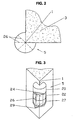
- FIGS 2 and 3 show the SE unit 5 greatly enlarged. It basically consists of three parts: located at the top the reflection part 20. He serves to that of the weapon reflected laser signal to reflect back on so that the weapon can locate the SE unit 5.
- the sensor 22 In the middle is the sensor 22. It consists of a number of sensor elements 24, each one sector monitor.
- the horizontal (virtual) trajectory 9 can for Examples in the division according to Figure 2 with a Resolution of 45 degrees can be determined.
- the sensor elements 24 may be conventional photosensitive elements that are shielded from each other by partitions 26 to the receive sector-shaped directional characteristic.
- the transmitter 27 At the bottom of the SE unit 5 is the transmitter 27.
- Er consists of a number of transmitter elements 29, each in covering about one sector of the environment of the SE unit.
- the SE unit 5 controls not shown, the SE unit 5, the transmission power of the transmitter elements 29, by the range of the radiated from the transmitting elements To control the effect signals and thus the shape of the Reproduce area 7.
- both the simulation device on the weapon as well as the SE unit 5 is by common means realizable.
- a threshold amplifier to be connected when receiving a signal responds. He causes everyone Transmitter element is supplied with energy of a certain height, 5 whereby the range of the effect signal in this direction is set. This will be a form of Impact area 7 modeled after the alignment of the respective sensor element 24 and thus the trajectory. 9 equivalent.
- Another possibility of controlling the SE unit 5 is the respective house 3 with one enough to equip powerful simulation computer that the monitored by the SE units, possibly also only in the environment of the house triggered weapons, especially the simulated type, determined and the corresponding Transmitter units 20 triggers. It is in this arrangement additionally possible, more, not in the SE units to provide integrated transmitter units and / or in the Range of action of each weapon located participants or equipment, for example via radio individually over theirs To inform the area of residence in the sphere of influence.
- this local arithmetic unit in principle also at any time Place and number of all participants in their vicinity, Equipment and weapons is informed, it can be complementary to the local SE units 5 the use of the weapons too then simulate, if not according to their actual Purpose, for example in direct fire, which may not be recognized by the SE units 5 can be. However, depending on this is with a certain Delay and thus lesser proximity to reality in the To calculate hit simulation.
Abstract
Description
Die vorliegende Erfindung bezieht sich auf ein Verfahren zur
Simulation der Wirkung von explodierenden Geschossen gemäss
Oberbegriff des Anspruchs 1. Des weiteren bezieht sich die
Erfindung auf eine Vorrichtung zur Durchführung des
Verfahrens gemäss Oberbegriff des ersten
Vorrichtungsanspruchs.The present invention relates to a method for
Simulation of the effect of exploding projectiles according to
The preamble of
Eine bekannte Art von detonierenden Geschossen sind diejenigen, die von ballistischen Waffen (Mörsern, Geschütze) abgefeuert werden. Für die Simulation werden aus der Geschützausrichtung und anderen Parametern die Flugbahn und die Detonationsstelle errechnet. Wegen der relativ langen Flugzeit von mehreren Sekunden kann diese Berechnung von einem Zentralrechner durchgeführt werden.A well-known kind of detonating projectiles are those of ballistic weapons (mortars, Guns) are fired. For the simulation will be off the gun alignment and other parameters the trajectory and the detonation point calculated. Because of the relative long flight time of several seconds, this calculation be performed by a central computer.
Aus der DE 198 03 337 A1 ist ein Verfahren zur Simulation der Bedrohung von Teilnehmem einer militärischen Übung durch Handgranaten oder Minen bekannt. Es dient zur realitätsnahen Simutation der Bedrohung von Übungsteilnehmern; insbesondere Soldaten und Fahrzeugen, durch Einzelminen, Minensperren und Handgranaten.DE 198 03 337 A1 discloses a method for simulating the threat of subscribers military exercise known by hand grenades or mines. It serves for realistic simutation the threat of practice participants; especially soldiers and vehicles, through individual mines, Mine locks and hand grenades.
Neuerdings gibt es jedoch auch Infanteriewaffen, die nach diesem Prinzip funktionieren. Im Wesentlichen handelt es sich dabei um eine gewehrähnliche Waffe. Der Schütze zielt dabei zum Beispiel auf eine Mauerkante eines Hauses. Die Zielvorrichtung bestimmt diese Entfernung und speichert sie. Der Schütze zielt danach an der Mauerecke vorbei und löst den Schuss aus. Das Geschoss fliegt die vorher bestimmte Strecke und detoniert an deren Endpunkt oder auch eine bestimmte Distanz davor oder dahinter. Im Wesentlichen ist es damit möglich, eine Trefferwirkung hinter der anvisierten Ecke zu erzielen. Einfach ausgedrückt ist es damit möglich, in gewissem Umfang "um die Ecke zu schiessen".Recently, however, there are also infantry weapons, the after work this principle. Essentially it acts this is a gun-like weapon. The shooter aims For example, on a wall edge of a house. The Target device determines this distance and stores it. The shooter then aims past the wall corner and releases the shot out. The projectile flies the previously determined Track and detonate at their end point or even one certain distance before or behind it. Essentially It makes it possible to hit behind the targeted one To achieve a corner. Simply put, it is possible to a certain extent "around the corner".
Da insbesondere die Flugzeit bei dieser Waffe eher im Bereich von Millisekunden liegt, ist es nicht möglich, die Wirkung dieser Waffe durch einen Zentralrechner zu simulieren, ohne dabei eine realitätsferne Verzögerung zwischen Schussauslösung und Wirkung hinnehmen zu müssen.Since in particular the time of flight with this weapon rather in the Range of milliseconds, it is not possible the Effect of this weapon through a central computer too simulate without a delay far from reality between shot firing and effect to have to accept.
Eine Aufgabe der vorliegenden Erfindung liegt daher darin, ein Verfahren anzugeben, um die Wirkung detonierender Geschosse zu simulieren, bei denen zwischen Abschuss und Detonation am Zielort realitätsnah geringe Verzögerungen auftreten.An object of the present invention is therefore to to provide a method to the effect of detonating To simulate projectiles where between launch and Detonation at the destination close to reality low delays occur.
Ein derartiges Verfahren ist im Anspruch 1 angegeben. Die
weiteren Ansprüche geben bevorzugte Ausführungsformen sowie
Vorrichtungen zur Ausführung des Verfahrens an.Such a method is specified in
Das erfindungsgemässe Verfahren zeichnet sich gemäss dem Hauptaspekt dadurch aus, das eine von der zu simulierenden Waffe ausgestrahlte Abschussinformation lokal erfasst und im Wirkungsbereich der simulierten Detonation ausgestrahlt wird, also insbesondere auch in dem Bereich, der vom Standpunkt des Schützen nicht einsehbar ist. Bevorzugt geschieht dies dadurch, dass an dem Hindernis eine Senderempfängereinheit vorhanden ist. Der Empfänger dieser Einheit nimmt die von der Waffe ausgesendete Information über den erfolgten Abschuss auf und aktiviert die Sendereinheit, die im Wirkungsgebiet die Information über die simulierte Detonation aussendet. In diesem Wirkungsgebiet befindliche Teilnehmer an der Übung, die entsprechende Empfänger aufweisen, werden dadurch darüber informiert, dass sie getroffen sind und aus der Übung ausscheiden oder als verletzt gelten.The inventive method is characterized according to the Main aspect by being one of the ones to be simulated Weapon emitted firing information recorded locally and in the Area of action of the simulated detonation broadcast , especially in the area covered by the Position of the shooter is not visible. Prefers This happens because of the fact that at the obstacle Transmitter receiver unit is present. The recipient of this Unit takes the information sent by the weapon on the successful launch and activates the Transmitter unit, the information in the area of action over the simulated detonation sends out. In this Area of action participants in the exercise, the have corresponding receiver, are about it inform that they are taken and out of the exercise retire or be considered injured.
In einer bevorzugten Ausführung wird zusätzlich festgestellt, aus welcher Richtung die Waffe auf das Hindernis gerichtet ist, um den Wirkungsraum der Detonation genauer abstecken zu können. Weiter bevorzugt weist dann auch die Sendereinheit die Möglichkeit auf, gezielt nur bestimmte Bereiche des möglichen Treffergebietes mit dem Wirkungssignal zu bestreichen.In a preferred embodiment is in addition Determined from which direction the weapon on the Obstacle is directed to the action space of the detonation be able to pinpoint more accurately. More preferably then points The sender unit also has the option to target only certain areas of the possible hit area with the Impact signal to brush.
Die Erfindung soll weiter an einem Ausführungsbeispiel unter
Bezugnahme auf Figuren erläutert werden.
An einer Mauerecke 1 eines angedeuteten Hauses 3 ist eine
erfindungsgemässe Senderempfängereinheit 5 angebracht. Sie
wird im weiteren kurz als SE-Einheit bezeichnet. Es ist noch
anzumerken, das die SE-Einheit 5 im Verhältnis zum
simulierten Detonations-Wirkungsraum 7 überdimensional gross
gezeichnet ist.At a
Ziel der Simulation ist, die Wirkung eines Geschosses zu
simulieren, das längs Flugbahn 9 heranfliegt und im Punkt 10
detoniert. Idealisierend wird angenommen, dass die Explosion
im Punkt 10 eine Wirkung im Raum 7 entfaltet. Die Flugbahn 9
ist dabei flach. Eine Voraussetzung für die Simulation ist,
dass die entsprechende Waffe mit einer Vorrichtung
ausgestattet ist, die in den von der Waffe einsehbaren
Zielbereich Schussinformation einstrahlt. In der Regel
handelt es sich dabei um eine Simulationsvorrichtung mit
Laserquelle. Die bekannten Ausführungen dieser Vorrichtungen
verfügen bereits über die Fähigkeit, Vorhalt und Aufsatz zu
kompensieren, indem der Laserstrahl gegenüber der
Zielrichtung seitlich und/oder in der Höhe abweichend in den
Zielraum abgestrahlt wird. Für explosive Geschosse und
andere Anwendungen ist es dabei bekannt, mit der
Laservorrichtung im anvisierten Gebiet eine grössere Fläche
abzutasten, d.h., den Laserstrahl zum Beispiel im Zickzack
über eine vorgegebene Fläche zu führen, um Detektoren in der
Ausrüstung von Geräten und Übungsteilnehmern im
Wirkungsgebiet zu aktivieren.The aim of the simulation is to increase the effect of a projectile
simulate flying along
Bei der der Simulation zugrunde liegenden Waffe wird
zunächst die Mauerecke 1 anvisiert. Der Laserstrahl der
Simulationeinrichtung an der Waffe trifft dabei auf die SE-Einheit
5. Der darin vorhandene Empfänger wird dadurch,
soweit nötig, in einen alarmierten Zustand versetzt. Der
Empfänger ist richtungsempfindlich, um wenigstens annähernd
die Richtung der Flugbahn 9 zu bestimmen. Die SE-Einheit
weist darüber hinaus eine Reflexionsvorrichtung 20 auf, die
den Laserstrahl auf sich selbst zurück reflektiert. Dadurch
ist es der Zieleinrichtung möglich, festzustellen, dass ihr
Strahl eine SE-Einheit 5 getroffen hat. Beim Ausrichten der
Waffe auf den Zielort 10 kann dann die Zielvorrichtung den
Laserstrahl derart gegenüber der Ausrichtung der Waffe
verschwenken oder aufweiten, dass er immer noch die SE-Einheit
5 trifft.In the simulation of the underlying weapon is
first the
Beim Auslösen der Waffe wird über den Laserstrahl eine
entsprechende Information an den Empfänger der SE-Einheit
übertragen. Dies aktiviert dann den Senderteil 27 der SE-Einheit
5, die im Wirkungsgebiet 7 das Treffersignal
abstrahlt. Im vorliegenden Beispiel wird angenommen, dass
das Wirkungsgebiet 7 im Wesentlichen eine Ellipse darstellt,
deren längere Achse senkrecht auf der Flugbahn 9 steht.
Geräte und/oder Simulationsteilnehmer, die sich im
Wirkungsgebiet 7 befinden und Detektoren für das Signal der
Sender der SE-Einheit 5 tragen, werden damit sofort bei
Auslösen des Schusses durch Aktivieren ihrer Sensoren
darüber informiert, dass sie der Wirkung dieser Waffe
ausgesetzt sind.When triggering the weapon becomes over the laser beam one
corresponding information to the receiver of the SE unit
transfer. This then activates
Mit anderen Worten setzt die SE-Einheit 5 das
Wirkungssignal, das von der Simulationseinrichtung der Waffe
abgestrahlt wird, in eines um, das das Treffergebiet 7
abdeckt, und zwar auch dort, wo das Treffersignal der Waffe
selbst aus physikalischen Gründen nicht hingelangen kann.In other words, the
Die Figur 2 und 3 zeigen die SE-Einheit 5 stark vergrössert.
Sie besteht im Wesentlichen aus drei Teilen: Oben befindet
sich der Reflexionsteil 20. Er dient dazu, das von der Waffe
ausgestrahlte Lasersignal auf sich zurück zu reflektieren,
so dass die Waffe die SE-Einheit 5 lokalisieren kann.Figures 2 and 3 show the
In der Mitte befindet sich der Sensor 22. Er besteht aus
einer Anzahl Sensorelemente 24, die jeweils einen Sektor
überwachen. Die horizontale (virtuelle) Flugbahn 9 kann zum
Bespiele bei der Aufteilung gemäss Figur 2 mit einer
Auflösung von 45 Grad bestimmt werden. Die Sensorelemente 24
können übliche fotoempfindliche Elemente sein, die
voneinander durch Trennwände 26 abgeschirmt sind, um die
sektorförmige Richtcharakteristik zu erhalten.In the middle is the
Unten in der SE-Einheit 5 befindet sich der Sender 27. Er
besteht aus einer Anzahl Senderelemente 29, die jeweils in
etwa einen Sektor der Umgebung der SE-Einheit abdecken.
Zusätzlich kontrolliert die nicht dargestellte Steuerung der
SE-Einheit 5 auch die Sendeleistung der Senderelemente 29,
um die Reichweite des von den Sendeelementen abgestrahlten
Wirkungssignales zu steuern und damit die Form des
Wirkungsgebietes 7 nachzubilden.At the bottom of the
Die Steuerung sowohl der Simulationseinrichtung an der Waffe
wie auch der SE-Einheit 5 ist mit gängigen Mitteln
realisierbar. Zum Beispiel kann mit jedem Sensorelement 24
ein Schwellwertverstärker verbunden sein, der bei Empfang
eines Signals anspricht. Er veranlasst, dass jedes
Senderelement mit Energie einer gewissen Höhe versorgt wird,
5 wodurch die Reichweite des Wirkungssignals in diese Richtung
eingestellt wird. Dadurch wird eine Form des
Wirkungsgebietes 7 nachgebildet, die der Ausrichtung des
jeweiligen Sensorelementes 24 und damit der Flugbahn 9
entspricht.The control of both the simulation device on the weapon
as well as the
Steuereinrichtungen für diesen Zweck sind dem Fachmann ohne weiteres zugänglich und brauchen daher nicht weiter im Detail erläutert werden.Control devices for this purpose are without the expert more accessible and therefore do not need further Detail will be explained.
Eine andere Möglichkeit der Steuerung der SE-Einheit 5
besteht darin, das jeweilige Haus 3 mit einem genügend
leistungsfähigen Simulationsrechner auszustatten, der die
von den SE-Einheiten überwachten, gegebenenfalls auch nur in
der Umgebung des Hauses ausgelösten Waffen, insbesondere des
simulierten Typs, ermittelt und die entsprechenden
Sendereinheiten 20 auslöst. In dieser Anordnung ist es
zusätzlich möglich, weitere, nicht in die SE-Einheiten
integrierte Sendereinheiten vorzusehen und/oder im
Wirkungsbereich der jeweiligen Waffe befindliche Teilnehmer
oder Gerätschaften zum Beispiel über Funk einzeln über ihren
Aufenthaltsbereich im Wirkungsbereich zu informieren. Da
diese lokale Recheneinheit prinzipiell auch jederzeit über
Ort und Anzahl aller in ihrer Nähe befindlichen Teilnehmer,
Gerätschaften und Waffen informiert ist, kann sie ergänzend
zu den lokalen SE-Einheiten 5 den Einsatz der Waffen auch
dann simulieren, wenn sie nicht gemäss ihrem eigentlichen
Zweck eingesetzt werden, zum Beispiel im direkten Beschuss,
der unter Umständen von den SE-Einheiten 5 nicht erkannt
werden kann. Je nachdem ist dabei aber mit einer gewissen
Verzögerung und damit geringerer Nähe zur Realität bei der
Treffersimulation zu rechnen.Another possibility of controlling the
Ausgehend von der vorangehenden Beschreibung eines
bevorzugten Ausführungsbeispiels sind dem Fachmann
abgewandelte Ausführungen zugänglich, ohne den Bereich der
Erfindung wie in den Ansprüchen definiert zu verlassen. Zum
Beispiel ist es möglich, bei geringeren Ansprüchen auf die
Richtungsempfindlichkeit des Senders 27 wie auch des Sensor
22 zu verzichten. Wird beim Sender 27 auf die
Reichweitensteuerung und insbesondere auch auf die
Richtcharakteristik verzichtet, so wird ein im Wesentlichen
kreisförmig die SE-Einheit umgebendes Wirkungsgebiet
simuliert. Ein Verzicht auf jegliche Richtcharakteristik der
Sensoreinheit könnte zwar im Extremfall noch hinnehmbar
sein, allerdings könnte dann die SE-Einheit auch nicht mehr
unterscheiden, ob die spezielle Waffe wie vorgesehen
eingesetzt wird und zum Beispiel direkt auf das Hindernis
gerichtet ist: In jedem Falle würde ein vorschriftsgemässer
Einsatz der Waffe angenommen.Starting from the preceding description of a
preferred embodiment are those skilled in the art
modified versions accessible without the scope of
Invention as defined in the claims to leave. To the
Example, it is possible to lower claims on the
Directional sensitivity of the
Anstelle von Licht (Laser) könnte auch an andere Mittel der Datenübertragungen gedacht werden, wie zum Beispiel Ultraschall oder auch Funksignale, insbesondere von hoher Frequenz, zum Beispiel 2,4 GHz. Generell eignen sich jedoch letztere wegen ihrer Empfindlichkeit gegen bestimmte Witterungsverhältnisse, die eigentlich den Ablauf der Simulation nicht wesentlich behindern sollten, weniger gut.Instead of light (laser) could also be to other means of Data transfers are thought of, such as Ultrasound or radio signals, in particular of high Frequency, for example 2.4 GHz. Generally, however, are suitable the latter because of their sensitivity to certain Weather conditions, which are actually the course of the Simulation should not significantly hinder, less well.
Weitere, denkbare Abwandlungen sind:
bewegliche Trennwände 26 zwischen Senderelementen, die entsprechend der Flugbahn 9 so ausgerichtet werden, dass mit den Senderelementen eine bessere Nachbildung des Wirkungsbereiches erzielt werden kann;- Ausbilden der Teile einer SE-Einheit (Reflektor, Sensor, Sender) als voneinander getrennte Teile, so dass insbesondere der Sender an einer für die Abstrahlung des Signals optimalen Stelle angeordnet wenden kann und/oder ein Sender von einer Mehrzahl Sensor/Reflektor-Einheiten angesteuert werden kann.
- SE-Einheit mit 360°-Erfassungsbereich, um z.B. auf einem Fahrzeug oder anderem Hindernis montiert zu werden und einen Schuss aus beliebiger Richtung auf das Hindernis mit Wirkung hinter dem Hindernis simulieren zu können.
- Zusätzliche Effekteinheit zur Erzeugung realitätsnaher Effekte wie Rauch, Knall, Lichtblitz.
-
movable partition walls 26 between transmitter elements, which are aligned in accordance with thetrajectory 9 so that with the transmitter elements a better replica of the effective range can be achieved; - Forming the parts of a SE-unit (reflector, sensor, transmitter) as separate parts, so that in particular the transmitter can turn arranged at an optimal location for the radiation of the signal and / or a transmitter driven by a plurality of sensor / reflector units can be.
- SE unit with 360 ° detection area, for example, to be mounted on a vehicle or other obstacle and to simulate a shot from any direction on the obstacle with effect behind the obstacle.
- Additional effects unit to produce realistic effects such as smoke, bang, flash of light.
Claims (11)
- Method for simulating the effect of exploding projectiles fired by weapons, characterized in that a signal emitted by the weapon when fired is detected by a sensor (22) located near the target location and the sensor prompts at least one associated transmitter (27) to emit an impact signal, whereby also that portion of the impact area (7) of the simulated explosion can be covered by means of the impact signal which cannot be covered by the signal of the weapon.
- Method according to claim 1, characterised in that the trajectory (9) of the simulated projectile is determined from the angle of incidence of the weapon signal on the sensor (22) and as a function of this, the signal emitted by the transmitter is directionally modified such that an improved approximation of the area covered by the impact signal to the impact area of a real projectile is accomplished.
- A device for carrying out the method according to one of claims 1 to 2, characterized in that the device comprises a sensor (22) and a transmitter (27), the sensor (22) being operatively linked to the transmitter (27) in such a manner that a signal of a weapon detected by the sensor and indicating the simulated firing of a projectile having an explosive impact in the target location prompts the emission of an impact signal in the impact location (7) of the simulated projectile by the transmitter (27), whereby also that portion of the impact area (7) of the simulated explosion can be covered by means of the impact signal which cannot be covered by the signal of the weapon.
- Device according-to claim 3, characterised in that the sensor (22) is directionally sensitive and preferably consists of a plurality of sensor elements (24) each of which covers a sector of the total angular range covered by the sensor (22) in order to determine the angle of incidence of the firing signal emitted by the weapon at least stepwise, and in that the transmitter (27) is adapted to emit the impact signal with a directionally variable range and particularly consists of a plurality of transmitter elements (29) each of which is adapted to supply approximately a sector with a controllable range, so that the transmitter (27) is capable of being triggered by the sensor (22) according to the angle of incidence of the firing signal of the weapon in such a manner that the area supplied by the transmitter with an effective impact signal represents a better approximation to the impact area (7) of a projectile exploding in reality.
- Device (1) according to one of claims 3 to 4, characterised in that the device comprises a reflector device (20) reflecting at least an effective portion of the firing signal emitted by the weapon back onto the weapon, so that the position of the reflector device can be determined by the simulation device on the weapon emitting the firing signal and the firing signal can be transmitted to the sensor (22) when the weapon is fired.
- Device according to one of claims 3 to 5, characterised in that the sensor (22) is a sensor for laser light.
- Device according to one of claims 3 to 6, characterised in that the transmitter (27) comprises at least one laser light source, preferably at least one laser diode, in order to be capable of emitting laser light as an impact signal.
- Device according to any one of claims 4 to 7, characterised in that the transmitter elements (29) are separated from each other by screens, in particular separating walls (26) which provide an essentially sectorial restriction of the hit signal emitted by the transmitter elements (29).
- Device according to claim 8, characterised in that the separating walls are adjustable in function of the angle of incidence of the firing signal of the weapon on the sensor in order to allow an improved adaptation of the area covered by the impact signal of the transmitter elements (29) to the impact area of a projectile exploding in reality.
- Device according to any one of claims 3 to 9, characterised in that the sensor (22) is sensitive to highfrequency radio signals and/or to ultrasonic signals, and/or in that the transmitter (27) is capable of emitting a highfrequency radio and/or ultrasonic signal as an impact signal.
- Installation for simulating combat action with at least one obstacle to visibility, particularly a house, the obstacle being provided at its periphery, particularly at least at one corner, with a device according to any one of claims 3 to 10, thus allowing the simulation of the effect of a weapon firing projectiles which explode-at the target location.
Applications Claiming Priority (2)
| Application Number | Priority Date | Filing Date | Title |
|---|---|---|---|
| CH23132000 | 2000-11-29 | ||
| CH23132000 | 2000-11-29 |
Publications (2)
| Publication Number | Publication Date |
|---|---|
| EP1213558A1 EP1213558A1 (en) | 2002-06-12 |
| EP1213558B1 true EP1213558B1 (en) | 2005-03-09 |
Family
ID=4568527
Family Applications (1)
| Application Number | Title | Priority Date | Filing Date |
|---|---|---|---|
| EP01811099A Expired - Lifetime EP1213558B1 (en) | 2000-11-29 | 2001-11-16 | Method and device for simulating exploding projectiles |
Country Status (11)
| Country | Link |
|---|---|
| US (1) | US7001182B2 (en) |
| EP (1) | EP1213558B1 (en) |
| JP (1) | JP2002228397A (en) |
| AT (1) | ATE290682T1 (en) |
| AU (1) | AU8934101A (en) |
| CA (1) | CA2361478C (en) |
| DE (1) | DE50105521D1 (en) |
| ES (1) | ES2237546T3 (en) |
| IL (1) | IL146422A (en) |
| NZ (1) | NZ515419A (en) |
| SG (1) | SG96259A1 (en) |
Families Citing this family (20)
| Publication number | Priority date | Publication date | Assignee | Title |
|---|---|---|---|---|
| SE521874C2 (en) * | 2001-01-10 | 2003-12-16 | Saab Ab | battle Simulation |
| CH697477B1 (en) * | 2003-05-15 | 2008-10-31 | Stefano Valentini | Device for the detection and recording of impacts produced by shock waves and by bullets on a target. |
| EP1519136A1 (en) * | 2003-09-23 | 2005-03-30 | Saab Ab | Nuclear, biological or chemical warfare simulator |
| DE602004010880T2 (en) * | 2004-03-26 | 2008-12-11 | Saab Ab | System and method for weapon effect simulation |
| US7927102B2 (en) * | 2005-01-13 | 2011-04-19 | Raytheon Company | Simulation devices and systems for rocket propelled grenades and other weapons |
| US7507089B2 (en) * | 2005-07-15 | 2009-03-24 | Raytheon Company | Methods and apparatus to provide training against improvised explosive devices |
| US7922491B2 (en) * | 2005-09-28 | 2011-04-12 | Raytheon Company | Methods and apparatus to provide training against improvised explosive devices |
| JP4954565B2 (en) * | 2006-02-10 | 2012-06-20 | 株式会社日立国際電気 | Laser transmitter / receiver |
| IL177080A0 (en) * | 2006-03-15 | 2007-08-19 | Israel Aerospace Ind Ltd | Combat training system and method |
| US20080241805A1 (en) * | 2006-08-31 | 2008-10-02 | Q-Track Corporation | System and method for simulated dosimetry using a real time locating system |
| US20080206718A1 (en) * | 2006-12-01 | 2008-08-28 | Aai Corporation | Apparatus, method and computer program product for weapon flyout modeling and target damage assessment |
| US8403672B2 (en) | 2009-10-21 | 2013-03-26 | Tim Odorisio | Training target for an electronically controlled weapon |
| KR101179074B1 (en) * | 2011-12-13 | 2012-09-05 | 국방과학연구소 | Airburst simulation apparatus and method of simulation for airbrust |
| FR2988859B1 (en) * | 2012-03-29 | 2015-03-13 | Nexter Systems | METHOD FOR ACQUIRING THE COORDINATES OF A PROJECTILE TRIGGER POINT AND TIR CONDUIT USING SUCH A METHOD |
| US9632168B2 (en) | 2012-06-19 | 2017-04-25 | Lockheed Martin Corporation | Visual disruption system, method, and computer program product |
| US9714815B2 (en) | 2012-06-19 | 2017-07-25 | Lockheed Martin Corporation | Visual disruption network and system, method, and computer program product thereof |
| DE102012106883A1 (en) * | 2012-07-27 | 2014-01-30 | Esw Gmbh | Method for simulating an extended range of action of a projectile |
| US9103628B1 (en) | 2013-03-14 | 2015-08-11 | Lockheed Martin Corporation | System, method, and computer program product for hostile fire strike indication |
| US9196041B2 (en) | 2013-03-14 | 2015-11-24 | Lockheed Martin Corporation | System, method, and computer program product for indicating hostile fire |
| US9146251B2 (en) | 2013-03-14 | 2015-09-29 | Lockheed Martin Corporation | System, method, and computer program product for indicating hostile fire |
Family Cites Families (22)
| Publication number | Priority date | Publication date | Assignee | Title |
|---|---|---|---|---|
| US3927480A (en) * | 1971-12-31 | 1975-12-23 | Saab Scania Ab | Gunnery training scoring system with laser pulses |
| US4273536A (en) * | 1980-01-28 | 1981-06-16 | The United States Of America As Represented By The Secretary Of The Air Force | Gun simulator system |
| DE3113068A1 (en) * | 1981-04-01 | 1982-12-30 | Johann F. Dipl.-Phys. 2000 Hamburg Hipp | Device for simulation of shots for directly aimed weapon systems in whose fire-control system a high-performance laser (high-power laser) is integrated for range measurement |
| DE3114000C2 (en) * | 1981-04-07 | 1983-04-28 | Precitronic Gesellschaft für Feinmechanik und Electronic mbH, 2000 Hamburg | Methods of shooting simulation and training for ballistic ammunition and moving targets |
| NO850503L (en) * | 1984-02-24 | 1985-08-22 | Noptel Ky | PROCEDURE FOR OPTICAL-ELECTRONIC EXERCISE SHOOTING. |
| US4682953A (en) * | 1985-07-09 | 1987-07-28 | L B & M Associates, Inc. | Combined arms effectiveness simulation system |
| US4752226A (en) * | 1987-04-29 | 1988-06-21 | Calspan Corporation | Chemical warfare simulator |
| US5228854A (en) * | 1992-07-21 | 1993-07-20 | Teledyne, Inc. | Combat training system and method |
| US5382958A (en) * | 1992-12-17 | 1995-01-17 | Motorola, Inc. | Time transfer position location method and apparatus |
| US5556281A (en) * | 1994-02-17 | 1996-09-17 | Motorola, Inc. | Simulated area weapons effects display arrangement |
| US5474452A (en) * | 1994-03-04 | 1995-12-12 | The United States Of America As Represented By The Secretary Of The Army | Training simulation system for indirect fire weapons such as mortars and artillery |
| US5571018A (en) * | 1994-11-23 | 1996-11-05 | Motorola, Inc. | Arrangement for simulating indirect fire in combat training |
| US5788500A (en) | 1995-12-04 | 1998-08-04 | Oerlikon-Contraves Ag | Continuous wave laser battlefield simulation system |
| US5914661A (en) * | 1996-01-22 | 1999-06-22 | Raytheon Company | Helmet mounted, laser detection system |
| DE19617060C2 (en) * | 1996-04-29 | 1998-07-23 | C O E L Entwicklungsgesellscha | Method and device for simulating the effects of steep arms on combat units |
| US5823779A (en) * | 1996-05-02 | 1998-10-20 | Advanced Interactive Systems, Inc. | Electronically controlled weapons range with return fire |
| US5941708A (en) * | 1996-05-24 | 1999-08-24 | Motorola, Inc. | Method for simulating temporal aspects of area weapons |
| US6254394B1 (en) * | 1997-12-10 | 2001-07-03 | Cubic Defense Systems, Inc. | Area weapons effect simulation system and method |
| DE19803337C2 (en) * | 1998-01-29 | 2002-11-21 | Dornier Gmbh | Procedure for simulating the threat to participants in a military exercise from hand grenades or mines |
| WO2000043973A1 (en) * | 1999-01-14 | 2000-07-27 | Explotrain, L.L.C. | Sytem and method for simulated device training |
| DE19915222A1 (en) * | 1999-04-03 | 2000-10-05 | Stn Atlas Elektronik Gmbh | Battlefield simulation method involves exchanging all data relevant to shell simulation via central station to which targets and participants are exclusively connected by radio |
| US6579097B1 (en) * | 2000-11-22 | 2003-06-17 | Cubic Defense Systems, Inc. | System and method for training in military operations in urban terrain |
-
2001
- 2001-11-06 SG SG200106983A patent/SG96259A1/en unknown
- 2001-11-08 CA CA002361478A patent/CA2361478C/en not_active Expired - Fee Related
- 2001-11-08 AU AU89341/01A patent/AU8934101A/en not_active Abandoned
- 2001-11-11 IL IL14642201A patent/IL146422A/en not_active IP Right Cessation
- 2001-11-12 NZ NZ515419A patent/NZ515419A/en unknown
- 2001-11-16 DE DE50105521T patent/DE50105521D1/en not_active Expired - Lifetime
- 2001-11-16 AT AT01811099T patent/ATE290682T1/en active
- 2001-11-16 EP EP01811099A patent/EP1213558B1/en not_active Expired - Lifetime
- 2001-11-16 ES ES01811099T patent/ES2237546T3/en not_active Expired - Lifetime
- 2001-11-28 US US09/996,211 patent/US7001182B2/en not_active Expired - Lifetime
- 2001-11-29 JP JP2001363782A patent/JP2002228397A/en active Pending
Also Published As
| Publication number | Publication date |
|---|---|
| ATE290682T1 (en) | 2005-03-15 |
| SG96259A1 (en) | 2003-05-23 |
| NZ515419A (en) | 2003-03-28 |
| ES2237546T3 (en) | 2005-08-01 |
| AU8934101A (en) | 2002-05-30 |
| EP1213558A1 (en) | 2002-06-12 |
| US20020064760A1 (en) | 2002-05-30 |
| DE50105521D1 (en) | 2005-04-14 |
| JP2002228397A (en) | 2002-08-14 |
| CA2361478A1 (en) | 2002-05-29 |
| IL146422A0 (en) | 2002-07-25 |
| IL146422A (en) | 2005-06-19 |
| CA2361478C (en) | 2009-02-17 |
| US7001182B2 (en) | 2006-02-21 |
Similar Documents
| Publication | Publication Date | Title |
|---|---|---|
| EP1213558B1 (en) | Method and device for simulating exploding projectiles | |
| EP1038150B1 (en) | Area weapons effect simulation system and method | |
| EP0609790B1 (en) | Dummy grenade | |
| US20030027103A1 (en) | Simulated weapon training and sensor system and associated methods | |
| DE2905422C2 (en) | Device for shot simulation with hit display | |
| DE10117007A1 (en) | Method and device for protecting mobile military equipment | |
| DE60207376T2 (en) | CHARACTERIZATION WHERE TARGET OBJECTS ARE ASSOCIATED WITH A PROTECTIVE OBJECT BY MEANS OF OWN COOPERATION BETWEEN THE TARGET OBJECTS AND THE PROTECTIVE OBJECTS CONCERNED | |
| DE19642091A1 (en) | Protection device for armored vehicles | |
| DE10230939A1 (en) | Fighting vehicle has warning sensors to detect and analyze threats and select optimum countermeasures using bus connected detachable munition projectors | |
| DE102005055099A1 (en) | Weapon e.g. mortar, simulation system for use in e.g. shoot training, has transceiver to determine horizontal orientation of weapon of participant through measures of another participant and transmit its current position per radio to system | |
| US8011928B1 (en) | Mine-like explosion simulator | |
| EP0547391A1 (en) | Method for increasing the success probability for an anti-aircraft defence system using remote-controlled scattering projectiles | |
| DE19617060C2 (en) | Method and device for simulating the effects of steep arms on combat units | |
| DE2522927C2 (en) | SYSTEM FOR REPLACEMENT, DISTRACTION AND DESTRUCTION OF ARMS | |
| DE4229509C2 (en) | Method and device for protecting radar stations against anti-radar missiles | |
| DE4029898A1 (en) | Mine-laying system with separately deployed sensors and warheads - covers hostile teritory with distributed sensor units returning signals to programmed warhead deployment and detonation system | |
| DE3326748C2 (en) | ||
| DE4031089A1 (en) | Mine system | |
| DE2633964A1 (en) | Fight simulator with electromagnetic radiation beam - produces divergent beam above exercise participant on approaching ground mine | |
| DE4135225C2 (en) | Methods for simulating the effect of mines on different mine targets and simulation mines for carrying out such a method | |
| EP1070225B1 (en) | Receiving unit, device and system for determining the position or movement of a weapon, and a method therefor | |
| DE102004039336B4 (en) | Device for improving performance and improving the evaluation in a combat training center | |
| DE4022330C1 (en) | Twin hollow charge shell use against actively armoured targets - has target sensor and time of flight sensor for objects incoming form target | |
| CH667523A5 (en) | Strike rate improvement appts. for weapon against airborne target - uses selective braking of fired shells with controlled detonation at optimum strike point at surface of imaginary sphere | |
| DE3920973A1 (en) | Three=dimensional defence system against operational land forces - uses combination of sensors, programmable devices and mines |
Legal Events
| Date | Code | Title | Description |
|---|---|---|---|
| PUAI | Public reference made under article 153(3) epc to a published international application that has entered the european phase |
Free format text: ORIGINAL CODE: 0009012 |
|
| AK | Designated contracting states |
Kind code of ref document: A1 Designated state(s): AT BE CH CY DE DK ES FI FR GB GR IE IT LI LU MC NL PT SE TR |
|
| AX | Request for extension of the european patent |
Free format text: AL;LT;LV;MK;RO;SI |
|
| RAP1 | Party data changed (applicant data changed or rights of an application transferred) |
Owner name: RUAG ELECTRONICS |
|
| 17P | Request for examination filed |
Effective date: 20021114 |
|
| AKX | Designation fees paid |
Designated state(s): AT BE CH CY DE DK ES FI FR GB GR IE IT LI LU MC NL PT SE TR |
|
| GRAP | Despatch of communication of intention to grant a patent |
Free format text: ORIGINAL CODE: EPIDOSNIGR1 |
|
| GRAS | Grant fee paid |
Free format text: ORIGINAL CODE: EPIDOSNIGR3 |
|
| GRAA | (expected) grant |
Free format text: ORIGINAL CODE: 0009210 |
|
| AK | Designated contracting states |
Kind code of ref document: B1 Designated state(s): AT BE CH CY DE DK ES FI FR GB GR IE IT LI LU MC NL PT SE TR |
|
| PG25 | Lapsed in a contracting state [announced via postgrant information from national office to epo] |
Ref country code: IE Free format text: LAPSE BECAUSE OF FAILURE TO SUBMIT A TRANSLATION OF THE DESCRIPTION OR TO PAY THE FEE WITHIN THE PRESCRIBED TIME-LIMIT Effective date: 20050309 Ref country code: TR Free format text: LAPSE BECAUSE OF FAILURE TO SUBMIT A TRANSLATION OF THE DESCRIPTION OR TO PAY THE FEE WITHIN THE PRESCRIBED TIME-LIMIT Effective date: 20050309 |
|
| REG | Reference to a national code |
Ref country code: GB Ref legal event code: FG4D Free format text: NOT ENGLISH |
|
| REG | Reference to a national code |
Ref country code: CH Ref legal event code: EP Ref country code: CH Ref legal event code: NV Representative=s name: AMMANN PATENTANWAELTE AG BERN |
|
| GBT | Gb: translation of ep patent filed (gb section 77(6)(a)/1977) |
Effective date: 20050309 |
|
| REG | Reference to a national code |
Ref country code: IE Ref legal event code: FG4D Free format text: GERMAN |
|
| REF | Corresponds to: |
Ref document number: 50105521 Country of ref document: DE Date of ref document: 20050414 Kind code of ref document: P |
|
| PG25 | Lapsed in a contracting state [announced via postgrant information from national office to epo] |
Ref country code: GR Free format text: LAPSE BECAUSE OF FAILURE TO SUBMIT A TRANSLATION OF THE DESCRIPTION OR TO PAY THE FEE WITHIN THE PRESCRIBED TIME-LIMIT Effective date: 20050609 Ref country code: DK Free format text: LAPSE BECAUSE OF FAILURE TO SUBMIT A TRANSLATION OF THE DESCRIPTION OR TO PAY THE FEE WITHIN THE PRESCRIBED TIME-LIMIT Effective date: 20050609 |
|
| REG | Reference to a national code |
Ref country code: SE Ref legal event code: TRGR |
|
| REG | Reference to a national code |
Ref country code: ES Ref legal event code: FG2A Ref document number: 2237546 Country of ref document: ES Kind code of ref document: T3 |
|
| PG25 | Lapsed in a contracting state [announced via postgrant information from national office to epo] |
Ref country code: PT Free format text: LAPSE BECAUSE OF FAILURE TO SUBMIT A TRANSLATION OF THE DESCRIPTION OR TO PAY THE FEE WITHIN THE PRESCRIBED TIME-LIMIT Effective date: 20050907 |
|
| REG | Reference to a national code |
Ref country code: IE Ref legal event code: FD4D |
|
| PG25 | Lapsed in a contracting state [announced via postgrant information from national office to epo] |
Ref country code: CY Free format text: LAPSE BECAUSE OF FAILURE TO SUBMIT A TRANSLATION OF THE DESCRIPTION OR TO PAY THE FEE WITHIN THE PRESCRIBED TIME-LIMIT Effective date: 20051116 |
|
| PG25 | Lapsed in a contracting state [announced via postgrant information from national office to epo] |
Ref country code: LU Free format text: LAPSE BECAUSE OF NON-PAYMENT OF DUE FEES Effective date: 20051130 Ref country code: MC Free format text: LAPSE BECAUSE OF NON-PAYMENT OF DUE FEES Effective date: 20051130 |
|
| ET | Fr: translation filed | ||
| PLBE | No opposition filed within time limit |
Free format text: ORIGINAL CODE: 0009261 |
|
| STAA | Information on the status of an ep patent application or granted ep patent |
Free format text: STATUS: NO OPPOSITION FILED WITHIN TIME LIMIT |
|
| 26N | No opposition filed |
Effective date: 20051212 |
|
| PGFP | Annual fee paid to national office [announced via postgrant information from national office to epo] |
Ref country code: NL Payment date: 20101111 Year of fee payment: 10 |
|
| PGFP | Annual fee paid to national office [announced via postgrant information from national office to epo] |
Ref country code: FI Payment date: 20101112 Year of fee payment: 10 |
|
| PGFP | Annual fee paid to national office [announced via postgrant information from national office to epo] |
Ref country code: BE Payment date: 20101117 Year of fee payment: 10 |
|
| PGFP | Annual fee paid to national office [announced via postgrant information from national office to epo] |
Ref country code: ES Payment date: 20101124 Year of fee payment: 10 |
|
| REG | Reference to a national code |
Ref country code: DE Ref legal event code: R082 Ref document number: 50105521 Country of ref document: DE Representative=s name: MAI DOERR BESIER PATENTANWAELTE, DE Ref country code: DE Ref legal event code: R082 Ref document number: 50105521 Country of ref document: DE Representative=s name: MAI DOERR BESIER EUROPEAN PATENT ATTORNEYS - E, DE |
|
| BERE | Be: lapsed |
Owner name: *RUAG ELECTRONICS Effective date: 20111130 |
|
| REG | Reference to a national code |
Ref country code: NL Ref legal event code: V1 Effective date: 20120601 |
|
| PG25 | Lapsed in a contracting state [announced via postgrant information from national office to epo] |
Ref country code: NL Free format text: LAPSE BECAUSE OF NON-PAYMENT OF DUE FEES Effective date: 20120601 |
|
| PG25 | Lapsed in a contracting state [announced via postgrant information from national office to epo] |
Ref country code: FI Free format text: LAPSE BECAUSE OF NON-PAYMENT OF DUE FEES Effective date: 20111116 Ref country code: BE Free format text: LAPSE BECAUSE OF NON-PAYMENT OF DUE FEES Effective date: 20111130 |
|
| REG | Reference to a national code |
Ref country code: ES Ref legal event code: FD2A Effective date: 20130603 |
|
| PG25 | Lapsed in a contracting state [announced via postgrant information from national office to epo] |
Ref country code: ES Free format text: LAPSE BECAUSE OF NON-PAYMENT OF DUE FEES Effective date: 20111117 |
|
| REG | Reference to a national code |
Ref country code: FR Ref legal event code: PLFP Year of fee payment: 15 |
|
| REG | Reference to a national code |
Ref country code: FR Ref legal event code: PLFP Year of fee payment: 16 |
|
| REG | Reference to a national code |
Ref country code: FR Ref legal event code: PLFP Year of fee payment: 17 |
|
| PGFP | Annual fee paid to national office [announced via postgrant information from national office to epo] |
Ref country code: CH Payment date: 20201125 Year of fee payment: 20 Ref country code: AT Payment date: 20201119 Year of fee payment: 20 Ref country code: IT Payment date: 20201124 Year of fee payment: 20 Ref country code: SE Payment date: 20201125 Year of fee payment: 20 Ref country code: FR Payment date: 20201120 Year of fee payment: 20 Ref country code: GB Payment date: 20201120 Year of fee payment: 20 Ref country code: DE Payment date: 20201119 Year of fee payment: 20 |
|
| REG | Reference to a national code |
Ref country code: DE Ref legal event code: R071 Ref document number: 50105521 Country of ref document: DE |
|
| REG | Reference to a national code |
Ref country code: GB Ref legal event code: PE20 Expiry date: 20211115 |
|
| REG | Reference to a national code |
Ref country code: SE Ref legal event code: EUG |
|
| REG | Reference to a national code |
Ref country code: AT Ref legal event code: MK07 Ref document number: 290682 Country of ref document: AT Kind code of ref document: T Effective date: 20211116 |
|
| PG25 | Lapsed in a contracting state [announced via postgrant information from national office to epo] |
Ref country code: GB Free format text: LAPSE BECAUSE OF EXPIRATION OF PROTECTION Effective date: 20211115 |