EP1213471A2 - Formgegossene drehbare Einrastverbindung für Kunstoffluftfilter - Google Patents
Formgegossene drehbare Einrastverbindung für Kunstoffluftfilter Download PDFInfo
- Publication number
- EP1213471A2 EP1213471A2 EP01204633A EP01204633A EP1213471A2 EP 1213471 A2 EP1213471 A2 EP 1213471A2 EP 01204633 A EP01204633 A EP 01204633A EP 01204633 A EP01204633 A EP 01204633A EP 1213471 A2 EP1213471 A2 EP 1213471A2
- Authority
- EP
- European Patent Office
- Prior art keywords
- wing
- slot
- housing portion
- housing
- post
- Prior art date
- Legal status (The legal status is an assumption and is not a legal conclusion. Google has not performed a legal analysis and makes no representation as to the accuracy of the status listed.)
- Withdrawn
Links
Images

Classifications
-
- F—MECHANICAL ENGINEERING; LIGHTING; HEATING; WEAPONS; BLASTING
- F02—COMBUSTION ENGINES; HOT-GAS OR COMBUSTION-PRODUCT ENGINE PLANTS
- F02M—SUPPLYING COMBUSTION ENGINES IN GENERAL WITH COMBUSTIBLE MIXTURES OR CONSTITUENTS THEREOF
- F02M35/00—Combustion-air cleaners, air intakes, intake silencers, or induction systems specially adapted for, or arranged on, internal-combustion engines
- F02M35/02—Air cleaners
- F02M35/0201—Housings; Casings; Frame constructions; Lids; Manufacturing or assembling thereof
- F02M35/0202—Manufacturing or assembling; Materials for air cleaner housings
- F02M35/0203—Manufacturing or assembling; Materials for air cleaner housings by using clamps, catches, locks or the like, e.g. for disposable plug-in filter cartridges
-
- B—PERFORMING OPERATIONS; TRANSPORTING
- B01—PHYSICAL OR CHEMICAL PROCESSES OR APPARATUS IN GENERAL
- B01D—SEPARATION
- B01D46/00—Filters or filtering processes specially modified for separating dispersed particles from gases or vapours
- B01D46/10—Particle separators, e.g. dust precipitators, using filter plates, sheets or pads having plane surfaces
-
- B—PERFORMING OPERATIONS; TRANSPORTING
- B01—PHYSICAL OR CHEMICAL PROCESSES OR APPARATUS IN GENERAL
- B01D—SEPARATION
- B01D2265/00—Casings, housings or mounting for filters specially adapted for separating dispersed particles from gases or vapours
- B01D2265/02—Non-permanent measures for connecting different parts of the filter
- B01D2265/028—Snap, latch or clip connecting means
-
- F—MECHANICAL ENGINEERING; LIGHTING; HEATING; WEAPONS; BLASTING
- F02—COMBUSTION ENGINES; HOT-GAS OR COMBUSTION-PRODUCT ENGINE PLANTS
- F02M—SUPPLYING COMBUSTION ENGINES IN GENERAL WITH COMBUSTIBLE MIXTURES OR CONSTITUENTS THEREOF
- F02M35/00—Combustion-air cleaners, air intakes, intake silencers, or induction systems specially adapted for, or arranged on, internal-combustion engines
- F02M35/02—Air cleaners
- F02M35/024—Air cleaners using filters, e.g. moistened
Definitions
- This invention relates to an air induction system employing a moldable snap fit connector for a filter housing cover.
- Air induction systems are used to provide clean air to a vehicle's engine.
- Such systems generally comprise a flow body, a filter housing and an air filter. Air is received into the flow body through an air intake and passes into the filter housing through a filter. The filter removes contaminants and particles that may otherwise interfere with the operation of the vehicle engine. Clean air then passes to the engine to combine with fuel in the combustion chamber.
- the filter housing typically comprises two halves that sandwich a filter between them. Frequently, a bolt on one half fits into a hole in another half. A wing-nut then tightens the two halves together, allowing for their assembly and disassembly by tightening and untightening the wing-nut. Vibrations experienced by the air induction system in the vehicle may cause the wing-nut to loosen, thereby loosening the filter within the housing.
- One recent proposed connector comprises a snap fit connection that has a wing on a post on one half of the filter housing and a slot on the other half.
- the wing twists into the slot and untwists following its passage through the slot, thereby creating an overlap between the wing and a portion of the space adjacent the slot.
- This current design provides benefits, but it would be desirable to simplify the molding of the features of the wing.
- the present invention comprises an air induction system having an airflow body, a filter housing, a filter, and a snap fit connector.
- the inventive connector has a wing on a post extending from one half of the housing and a slot to receive the wing on the other housing.
- the invention has a cutout adjacent to the post to facilitate the molding of the wing's features.
- the invention accordingly provides a moldable snap fit connection for a filter housing.
- a guide may be employed to twist the wing into the slot.
- the guide may be a ramp. Once the wing passes through the slot, the wing is no longer guided and returns to its untwisted position. In this untwisted position, the wing overlaps a portion of the housing having the slot.
- the wing and slot combine to sandwich a filter between the housing halves.
- the wing itself may be in the shape of a blade.
- the invention may comprise a filter housing for an air induction system.
- the housing has two halves.
- a filter is sandwiched between the halves.
- a connector comprises a wing on a post and extends from one of the halves. Cutouts are adjacent the post to permit molding of the wing's features.
- a guide on the other half causes the wing to twist into the slot. The wing untwists once through, locking the halves together.
- the wing may overlay a portion of the housing with the slot.
- the post has a first portion extending laterally outwardly from a flange portion of the housing.
- the post also has a second portion extending at an angle with a substantial portion generally perpendicular to the first portion such that cutouts are provided by sides of the housing.
- the wing has a relaxed position generally extending along a first line.
- the slot extends along a second line, non-parallel to the first line so that the wing moves through the slot and twists away from the relaxed position.
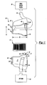
- FIG. 1 illustrates an embodiment of the invention in its environment. Shown are filter housing 20 comprising first portion 36 and second portion 40. As known, first housing portion 36 and second housing portion 40 sandwich air filter 44 when these portions are locked together. Air is received into air intake 24 and passes through air flow body 32 through opening 52 into first housing portion 36. Air is then cleaned by air filter 44 and passes through opening 48 of second housing portion 40 into air flow body 32 and ultimately to motor vehicle engine 28.
- the invention here employs a connector comprising wings 54 and slots 56.
- cutouts 60 are formed on first housing portion 36, to allow the wings 54 to be easily molded through conventional plastic molding processes.
- Flange 37 of first housing portion 36 has portions removed to allow underside of wing 54 to be formed by molding.
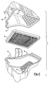
- FIGS 2 and 3 illustrate another view of the filter housing 20 of Figure 1.
- Filter housing 20 comprises a first housing portion 36 and second housing portion 40. Wings 54 are molded to first housing portion 36 while slots 56 are on second housing portion 40 to receive wings 54.
- filter 44 is sandwiched between first housing portion 36 and second housing portion 40 following the placement of wings 54 into slots 56.
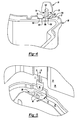
- Figure 4 illustrates in detail wings 54 and first housing portion 36 of the previous figures.
- Wing 54 such as in the shape of a blade, is connected to first housing portion 36 by post 72.
- Wing 54 has the shape of a blade.
- the first housing portion 36 has at least one cutout 60 adjacent post 72. Cutouts 60 allow wing 54 to be easily molded to have shoulders 76. Cutouts 60 greatly simplify the molding process because they permit shoulder 76 to be molded in the same line of draw as the other features of the filter housing.
- the cutouts 60 provide a laterally outwardly extending portion 100 of the post 72 which leads to an axially extending portion 102, which extends at an angle generally perpendicular to the section 100.
- edges 104 of the post portion 100 are spaced from edges 106 in the flange 37. This provides the cutouts, and simplifies the molding process.
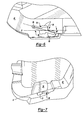
- Figure 5 illustrates how wing 54 fits into slot 56.
- wing 54 moves in the direction of arrow B towards slot 56. If untwisted, wing 54 would unsuccessfully attempt to enter slot 56 along line D. That is, wing 54 extends (along line D) in a relaxed position at an angle relative to slot 56 when first housing portion 36 and second housing portion 40 are brought together. Line D is transverse to slot 56 as illustrated, in one embodiment 18° to slot 56.
- guides or ramps 80 contact wing 54 and cam wing 54, causing post and wing 54 to twist in the direction of arrow C. If slot 56 is 18° transverse to line D, then wing 54 twists 18° to permit wing 54 to be received by slot 56.
- wing 54 twists and snaps into slot 56. Cutouts 60 permit wing 54 to be molded with no additional actions or complexities in the injection mold tools.
- wing 54 may be twisted in a direction to line the edge of the wing with the slot 56, opposite the direction of arrow C of Figure 9, and then pushing wing 54 through slot 56.
- a significant advantage of this connector is that it is under load at two opposing ends of the wing. Thus, post is not bent. By loading in this manner, the wing tends to have better retention because the plastic tends to creep under load.
- the key design features for serviceability of the filter housing are the blade size and the thickness of the stem that must be twisted to open the connector.
- the wing should be large enough to allow the wing to be twisted by hand.
- the post should be thin enough to permit easy twisting of wing.
Applications Claiming Priority (2)
| Application Number | Priority Date | Filing Date | Title |
|---|---|---|---|
| US25424500P | 2000-12-08 | 2000-12-08 | |
| US254245P | 2000-12-08 |
Publications (2)
| Publication Number | Publication Date |
|---|---|
| EP1213471A2 true EP1213471A2 (de) | 2002-06-12 |
| EP1213471A3 EP1213471A3 (de) | 2003-05-14 |
Family
ID=22963506
Family Applications (1)
| Application Number | Title | Priority Date | Filing Date |
|---|---|---|---|
| EP01204633A Withdrawn EP1213471A3 (de) | 2000-12-08 | 2001-11-30 | Formgegossene drehbare Einrastverbindung für Kunstoffluftfilter |
Country Status (2)
| Country | Link |
|---|---|
| US (1) | US6723148B2 (de) |
| EP (1) | EP1213471A3 (de) |
Cited By (1)
| Publication number | Priority date | Publication date | Assignee | Title |
|---|---|---|---|---|
| FR2848612A1 (fr) * | 2002-12-16 | 2004-06-18 | Renault Sa | Filtre a air pour moteur a combustion interne, et moteur equipe dudit filtre |
Families Citing this family (25)
| Publication number | Priority date | Publication date | Assignee | Title |
|---|---|---|---|---|
| DE10053983C1 (de) * | 2000-10-31 | 2002-06-27 | Montaplast Gmbh | Verschlussvorrichtung |
| US6726871B2 (en) * | 2001-06-07 | 2004-04-27 | Siemens Vdo Automotive, Inc. | Method and apparatus for attachment of air cleaner housing |
| WO2003006138A1 (en) * | 2001-07-13 | 2003-01-23 | Hemerus Medical, Llc | Snap together filter |
| US7263827B2 (en) * | 2003-04-04 | 2007-09-04 | Honda Motor Co., Ltd. | Exhaust pipe insulator attaching structure for saddle-riding vehicle |
| US6890366B2 (en) * | 2003-04-17 | 2005-05-10 | Visteon Global Technologies, Inc. | Sealed engine air filter system |
| US7294161B2 (en) | 2003-10-21 | 2007-11-13 | Fleetguard, Inc. | Filter with rotational end cap base retention |
| US7063730B2 (en) * | 2003-10-21 | 2006-06-20 | Fleetguard, Inc. | Filter with end cap base retainer |
| US20070012281A1 (en) * | 2004-12-20 | 2007-01-18 | Mann & Hummel Gmbh | Filter housing and method for manufacturing the same |
| US7294178B2 (en) * | 2004-11-08 | 2007-11-13 | Visteon Global Technologies, Inc. | Low loss hydrocarbon (HC) adsorber device for air induction system |
| US7168417B2 (en) * | 2005-04-08 | 2007-01-30 | Visteon Global Technologies, Inc. | Low airflow loss hydrocarbon trap |
| US7828869B1 (en) * | 2005-09-20 | 2010-11-09 | Cummins Filtration Ip, Inc. | Space-effective filter element |
| DE102011006584A1 (de) * | 2011-03-31 | 2012-10-04 | Hilti Aktiengesellschaft | Staubsauger |
| DE102006047451B4 (de) * | 2006-10-07 | 2021-11-04 | Andreas Stihl Ag & Co. Kg | Handgeführtes Arbeitsgerät |
| EP2094369B1 (de) * | 2006-12-08 | 2012-02-01 | MAHLE International GmbH | Filtergehäuse und herstellungsverfahren |
| DE102006060276B4 (de) * | 2006-12-20 | 2009-12-17 | Dr. Ing. H.C. F. Porsche Aktiengesellschaft | Luftfilter |
| KR20090011216A (ko) * | 2007-07-25 | 2009-02-02 | 삼성전자주식회사 | 공기 필터링 장치 및 그를 구비한 반도체 제조설비의청정시스템 |
| US8337579B2 (en) * | 2010-11-09 | 2012-12-25 | Honda Motor Company, Ltd. | Air cleaner assemblies and vehicles including same |
| DE102015006496A1 (de) * | 2015-05-22 | 2016-11-24 | Mann + Hummel Gmbh | Filterelement, insbesondere zur Gasfiltration |
| AU2016259419B2 (en) * | 2015-11-30 | 2020-12-10 | Parker-Hannifin Corporation | Engine Panel Filter and Housing System |
| JP2018112145A (ja) * | 2017-01-12 | 2018-07-19 | トヨタ紡織株式会社 | 内燃機関のエアクリーナ |
| US10336536B2 (en) * | 2017-03-06 | 2019-07-02 | Joseph Malik Glisson | System and device for yard waste collection |
| US10603616B1 (en) | 2017-08-24 | 2020-03-31 | American Air Filter Company, Inc. | Reusable filter frame |
| US11633683B2 (en) | 2018-01-12 | 2023-04-25 | Cummins Filtration Ip, Inc. | Easy to service air filter |
| US11554334B2 (en) * | 2018-11-27 | 2023-01-17 | Cummins Power Generation Ip, Inc. | Air cleaner |
| CN115789806B (zh) * | 2022-11-16 | 2024-01-16 | 北京市第五建筑工程集团有限公司 | 一种多功能医院送风天花系统 |
Citations (5)
| Publication number | Priority date | Publication date | Assignee | Title |
|---|---|---|---|---|
| GB1053111A (de) * | ||||
| US2887177A (en) * | 1958-02-18 | 1959-05-19 | Donaldson Co Inc | Air cleaner construction |
| US5295602A (en) * | 1993-03-17 | 1994-03-22 | General Motors Corporation | Housing with snap latch closure |
| US5628533A (en) * | 1995-10-23 | 1997-05-13 | Yazaki Corporation | Torsional snap-fit latch |
| DE19831496A1 (de) * | 1998-07-14 | 2000-01-20 | Stihl Maschf Andreas | Schnappverschluß |
Family Cites Families (12)
| Publication number | Priority date | Publication date | Assignee | Title |
|---|---|---|---|---|
| US3825110A (en) | 1972-07-14 | 1974-07-23 | F Halbich | Plastic case for glasses |
| IT1134176B (it) * | 1980-11-05 | 1986-07-31 | Itw Fastex Italia Spa | Disposizione di collegamento di un filtro dell'aria per autoveicoli al relativo carburatore e del coperchio del filtro al filtro stesso |
| US4743281A (en) | 1987-03-27 | 1988-05-10 | White Consolidated Industries, Inc. | Filter panel assembly |
| JPH0443507Y2 (de) | 1987-04-15 | 1992-10-14 | ||
| US5613759A (en) | 1991-06-24 | 1997-03-25 | Brod & Mcclung-Pace Co. | Light and filter support structure |
| US5836412A (en) * | 1993-11-22 | 1998-11-17 | Textron, Inc. | Method of assembling a golf car |
| JP3299622B2 (ja) * | 1994-03-11 | 2002-07-08 | 豊田紡織株式会社 | エアクリーナ装置 |
| US5947462A (en) | 1996-10-02 | 1999-09-07 | Jacuzzi, Inc. | Latching mechanism for fluid containment assembly |
| US6125501A (en) * | 1999-01-08 | 2000-10-03 | Yip; Chung Lun | Vacuum cleaner using a sheet filter |
| US6174343B1 (en) * | 1999-06-29 | 2001-01-16 | Siemens Canada Limited Ontario | Cam action attachment and locking mechanism for air cleaner shells |
| US6406508B1 (en) * | 1999-10-07 | 2002-06-18 | Siemens Canada Limited | Torsional snap fit connector for air filter cover |
| US6513481B2 (en) * | 2000-12-08 | 2003-02-04 | Siemens Vdo Automotive Inc. | Non rectangular shaped flexible panel air filter cartridge |
-
2001
- 2001-11-21 US US09/990,034 patent/US6723148B2/en not_active Expired - Lifetime
- 2001-11-30 EP EP01204633A patent/EP1213471A3/de not_active Withdrawn
Patent Citations (5)
| Publication number | Priority date | Publication date | Assignee | Title |
|---|---|---|---|---|
| GB1053111A (de) * | ||||
| US2887177A (en) * | 1958-02-18 | 1959-05-19 | Donaldson Co Inc | Air cleaner construction |
| US5295602A (en) * | 1993-03-17 | 1994-03-22 | General Motors Corporation | Housing with snap latch closure |
| US5628533A (en) * | 1995-10-23 | 1997-05-13 | Yazaki Corporation | Torsional snap-fit latch |
| DE19831496A1 (de) * | 1998-07-14 | 2000-01-20 | Stihl Maschf Andreas | Schnappverschluß |
Cited By (1)
| Publication number | Priority date | Publication date | Assignee | Title |
|---|---|---|---|---|
| FR2848612A1 (fr) * | 2002-12-16 | 2004-06-18 | Renault Sa | Filtre a air pour moteur a combustion interne, et moteur equipe dudit filtre |
Also Published As
| Publication number | Publication date |
|---|---|
| US6723148B2 (en) | 2004-04-20 |
| EP1213471A3 (de) | 2003-05-14 |
| US20020069625A1 (en) | 2002-06-13 |
Similar Documents
| Publication | Publication Date | Title |
|---|---|---|
| US6723148B2 (en) | Moldable twist lock snap fit design for plastic air cleaner | |
| EP1647701B1 (de) | Luftfilter | |
| US6998043B2 (en) | Fuel strainer assembly | |
| US6170516B1 (en) | Solenoid valve fixing structure | |
| US6422197B1 (en) | Intake system | |
| US9127628B2 (en) | Flange fastening structure | |
| EP0720257A2 (de) | Steckversinder Deckel | |
| US5967116A (en) | Joint structure of air intake system having throttle body | |
| JPH09203357A (ja) | 内燃機関の吸気ダクトおよび吸気装置 | |
| US5820401A (en) | Wire guide assembly for use with an electrical connector having a jack screw | |
| US7993424B2 (en) | Air cleaner | |
| US7823442B2 (en) | Throttle position sensor assembly | |
| US6564766B2 (en) | Air induction system for an automobile | |
| US6694940B2 (en) | Air intake device held between directly connected air cleaner case and intake manifold | |
| US6427674B1 (en) | Socket coil-on-plug retainer | |
| US6491734B1 (en) | Air cleaner for internal combustion engine with internally formed air inlet pipe | |
| CA2102277A1 (en) | Toggle catch for intake air filters of internal-combustion engines, compressors and other machines which take in air | |
| US6470768B2 (en) | Accelerator with attachment of pedal arm | |
| JP4759552B2 (ja) | 燃料噴射弁の取付構造 | |
| US6131445A (en) | Fuel tank sensor assembly | |
| US20040093839A1 (en) | Intake system | |
| US6659432B2 (en) | Carburetor arrangement | |
| EP0787613A3 (de) | Luftansaugvorrichtung für Brennkraftmaschine | |
| US20130026402A1 (en) | Anti-rotation structure for a valve installed in an exhaust boss of a reductant delivery system | |
| US20040231643A1 (en) | Throttle housing comprising a modular lid element |
Legal Events
| Date | Code | Title | Description |
|---|---|---|---|
| PUAI | Public reference made under article 153(3) epc to a published international application that has entered the european phase |
Free format text: ORIGINAL CODE: 0009012 |
|
| AK | Designated contracting states |
Kind code of ref document: A2 Designated state(s): AT BE CH CY DE DK ES FI FR GB GR IE IT LI LU MC NL PT SE TR |
|
| AX | Request for extension of the european patent |
Free format text: AL;LT;LV;MK;RO;SI |
|
| PUAL | Search report despatched |
Free format text: ORIGINAL CODE: 0009013 |
|
| AK | Designated contracting states |
Designated state(s): AT BE CH CY DE DK ES FI FR GB GR IE IT LI LU MC NL PT SE TR |
|
| AX | Request for extension of the european patent |
Extension state: AL LT LV MK RO SI |
|
| RIC1 | Information provided on ipc code assigned before grant |
Ipc: 7F 02M 35/02 B Ipc: 7F 02M 35/024 A |
|
| AKX | Designation fees paid |
Designated state(s): DE FR GB |
|
| STAA | Information on the status of an ep patent application or granted ep patent |
Free format text: STATUS: THE APPLICATION IS DEEMED TO BE WITHDRAWN |
|
| 18D | Application deemed to be withdrawn |
Effective date: 20031115 |