EP1213003A1 - Recessed part forming instillation container - Google Patents
Recessed part forming instillation container Download PDFInfo
- Publication number
- EP1213003A1 EP1213003A1 EP00951999A EP00951999A EP1213003A1 EP 1213003 A1 EP1213003 A1 EP 1213003A1 EP 00951999 A EP00951999 A EP 00951999A EP 00951999 A EP00951999 A EP 00951999A EP 1213003 A1 EP1213003 A1 EP 1213003A1
- Authority
- EP
- European Patent Office
- Prior art keywords
- container
- eye drops
- container body
- barrel portion
- instilling
- Prior art date
- Legal status (The legal status is an assumption and is not a legal conclusion. Google has not performed a legal analysis and makes no representation as to the accuracy of the status listed.)
- Granted
Links
Images



Classifications
-
- G—PHYSICS
- G01—MEASURING; TESTING
- G01F—MEASURING VOLUME, VOLUME FLOW, MASS FLOW OR LIQUID LEVEL; METERING BY VOLUME
- G01F11/00—Apparatus requiring external operation adapted at each repeated and identical operation to measure and separate a predetermined volume of fluid or fluent solid material from a supply or container, without regard to weight, and to deliver it
- G01F11/02—Apparatus requiring external operation adapted at each repeated and identical operation to measure and separate a predetermined volume of fluid or fluent solid material from a supply or container, without regard to weight, and to deliver it with measuring chambers which expand or contract during measurement
- G01F11/08—Apparatus requiring external operation adapted at each repeated and identical operation to measure and separate a predetermined volume of fluid or fluent solid material from a supply or container, without regard to weight, and to deliver it with measuring chambers which expand or contract during measurement of the diaphragm or bellows type
- G01F11/082—Apparatus requiring external operation adapted at each repeated and identical operation to measure and separate a predetermined volume of fluid or fluent solid material from a supply or container, without regard to weight, and to deliver it with measuring chambers which expand or contract during measurement of the diaphragm or bellows type of the squeeze container type
-
- A—HUMAN NECESSITIES
- A61—MEDICAL OR VETERINARY SCIENCE; HYGIENE
- A61F—FILTERS IMPLANTABLE INTO BLOOD VESSELS; PROSTHESES; DEVICES PROVIDING PATENCY TO, OR PREVENTING COLLAPSING OF, TUBULAR STRUCTURES OF THE BODY, e.g. STENTS; ORTHOPAEDIC, NURSING OR CONTRACEPTIVE DEVICES; FOMENTATION; TREATMENT OR PROTECTION OF EYES OR EARS; BANDAGES, DRESSINGS OR ABSORBENT PADS; FIRST-AID KITS
- A61F9/00—Methods or devices for treatment of the eyes; Devices for putting in contact-lenses; Devices to correct squinting; Apparatus to guide the blind; Protective devices for the eyes, carried on the body or in the hand
- A61F9/0008—Introducing ophthalmic products into the ocular cavity or retaining products therein
-
- B—PERFORMING OPERATIONS; TRANSPORTING
- B65—CONVEYING; PACKING; STORING; HANDLING THIN OR FILAMENTARY MATERIAL
- B65D—CONTAINERS FOR STORAGE OR TRANSPORT OF ARTICLES OR MATERIALS, e.g. BAGS, BARRELS, BOTTLES, BOXES, CANS, CARTONS, CRATES, DRUMS, JARS, TANKS, HOPPERS, FORWARDING CONTAINERS; ACCESSORIES, CLOSURES, OR FITTINGS THEREFOR; PACKAGING ELEMENTS; PACKAGES
- B65D1/00—Rigid or semi-rigid containers having bodies formed in one piece, e.g. by casting metallic material, by moulding plastics, by blowing vitreous material, by throwing ceramic material, by moulding pulped fibrous material or by deep-drawing operations performed on sheet material
- B65D1/02—Bottles or similar containers with necks or like restricted apertures, designed for pouring contents
- B65D1/08—Bottles or similar containers with necks or like restricted apertures, designed for pouring contents adapted to discharge drops
-
- B—PERFORMING OPERATIONS; TRANSPORTING
- B65—CONVEYING; PACKING; STORING; HANDLING THIN OR FILAMENTARY MATERIAL
- B65D—CONTAINERS FOR STORAGE OR TRANSPORT OF ARTICLES OR MATERIALS, e.g. BAGS, BARRELS, BOTTLES, BOXES, CANS, CARTONS, CRATES, DRUMS, JARS, TANKS, HOPPERS, FORWARDING CONTAINERS; ACCESSORIES, CLOSURES, OR FITTINGS THEREFOR; PACKAGING ELEMENTS; PACKAGES
- B65D23/00—Details of bottles or jars not otherwise provided for
- B65D23/10—Handles
- B65D23/102—Gripping means formed in the walls, e.g. roughening, cavities, projections
-
- B—PERFORMING OPERATIONS; TRANSPORTING
- B65—CONVEYING; PACKING; STORING; HANDLING THIN OR FILAMENTARY MATERIAL
- B65D—CONTAINERS FOR STORAGE OR TRANSPORT OF ARTICLES OR MATERIALS, e.g. BAGS, BARRELS, BOTTLES, BOXES, CANS, CARTONS, CRATES, DRUMS, JARS, TANKS, HOPPERS, FORWARDING CONTAINERS; ACCESSORIES, CLOSURES, OR FITTINGS THEREFOR; PACKAGING ELEMENTS; PACKAGES
- B65D47/00—Closures with filling and discharging, or with discharging, devices
- B65D47/04—Closures with discharging devices other than pumps
- B65D47/06—Closures with discharging devices other than pumps with pouring spouts or tubes; with discharge nozzles or passages
- B65D47/18—Closures with discharging devices other than pumps with pouring spouts or tubes; with discharge nozzles or passages for discharging drops; Droppers
Definitions
- the present invention relates to an eye drops container for containing a solution of medicine therein, and more particularly to an eye drops container composed of a hollow cylinder having flexibility at least at a barrel portion thereof.
- hollow cylindrical containers are widely in use.
- a container composed of a hollow cylindrical container body with an inner nozzle tip attached thereto and a container unitary molded a barrel portion of its container body and a liquid instilling portion by means of the blow molding method or vacuum molding method are currently available (see Japanese published utility model gazette No. Sho. 39-11991 for example).
- soft thermoplastic resin is generally employed for readiness of its molding.
- the barrel portion of the container will be gripped with two fingers and then the container will be held still at an instilling posture with the instilling nozzle facing an eye to be dispensed with the medicine. Kept under this posture, the barrel portion of the container will be pressed toward the center axis of the container body, thereby to supply a drop of the solution of medicine from the instilling nozzle of the container.
- the cylindrical hollow container body is formed of soft thermoplastic resin.
- a person with weak physical strength for the pressing action such as an aged person, will often find it difficult to control the pressing action.
- person with weak gripping strength such as an aged person, may find it difficult also to maintain the finger gripping position in a stable manner.
- the present invention has been made in view of the above-described state of the art and its primary object is to provide a handier eye drops container which provides superior "squeezability" and greater gripping ease through simple and inexpensive modification in the barrel portion of the container.
- the container includes a flexible hollow cylindrical barrel portion defining a dent portion which can be gripped with two fingers.
- the dent portion defined in the barrel portion of the container will be gripped with two fingers, so that the gripping position at the tips of the fingers may be maintained in a stable manner. Moreover, when the barrel portion of the container is pressed, the part of this barrel portion contacting the finger tips is dented in advance, so that the force required for the pressing action may be reduced, compared with a case where the part of the cylindrical barrel portion has to be deformed against the elastic resilience.
- the eye drops container is easier to be gripped and provides superior squeezability with reduced pressing force required. Consequently, there has been achieved an eye drops container having a dent portion easier to use which dropper allows accurate and easy instillation of a solution of medicine from the container.
- the dent portion comprises flat or substantially flat gripping faces which are formed concave respectively at two peripheral portions of the barrel portion.
- the dent portion comprises curved concave gripping faces which are formed concave respectively at two peripheral portions of the barrel portion, each gripping face being progressively closer to a central axis of the container body as the face extends toward the longitudinal center of the central axis.
- the container body having the barrel portion comprises a container body made of thermoplastic resin material which is filled with liquid simultaneously with its forming operation.
- Figs. 1 through 5 show an eye drops container having a dent portion according to the present invention mainly for use in medical treatment.
- the dropper includes a container body A made of thermoplastic resin material and charged with a predetermined amount of a solution of medicine therein simultaneously with the blow molding or vacuum molding thereof, and a cap B detachably threaded to a male thread 5a of a threaded cylindrical portion 5 of the container body A.
- the container body A includes a circular bottom 1 which is curved inwardly, a hollow cylindrical barrel portion 2 extending continuously from its peripheral edge, a cylindrical neck portion 3 extending continuously from a shoulder 2a of the barrel portion 2, a circular ring-like stepped portion 4 extending radially outward from an upper portion of the neck portion 3, the threaded cylindrical portion 5 extending continuously and upwardly from the stepped portion and having the male thread 5a, and a solution instilling cylindrical portion 6 extending continuously and upwardly from the threaded cylindrical portion and having a instilling nozzle 6a.
- thermoplastic resin material forming this container body A can be polyethylene, polyethylene-polypropylene, polypropylene, polyethylene terephthalate, polycarbonate, etc.
- the entire formed container body A can be elastically deformed.
- the solution instilling cylindrical portion 6 of the container body A defines a recess 6b in the form of a conical recess with a bottom, the recess having a progressively increasing inner diameter toward the instilling nozzle 6a.
- a small instilling nozzle hole 6c which allows control of a solution instilling amount to be pushed out of the container body A in association of a pressing action on the barrel portion 2 with fingers to a predetermined amount.
- the recess 6b has a depth ranging between 2 mm and 7 mm, preferably between 5 mm and 7 mm, and most preferably 6 mm. Also, the aperture (aperture diameter) of the liquid outlet 6a may be adjusted within a range of ⁇ 2.0 mm to ⁇ 4.0 mm, depending on the property of the solution of medicine.
- the aperture of the instilling nozzle 6a will be reduced.
- the aperture of the instilling nozzle 6a will be increased.
- the instilling nozzle hole 6c is formed by using a needle having a diameter ranging between ⁇ 0.1 mm and ⁇ 0.8 mm.
- a diameter of about ⁇ 0.2 mm is most preferred.
- a needle in the range from ⁇ 0.4 mm to ⁇ 0.6 mm is employed.
- the barrel portion 2 of the container body A forms a dent portion 7 which can be gripped with two fingers. Further, this dent portion 7 comprises a pair of gripping faces 7a which are formed as flat or substantially flat recesses provided at two peripheral portions of the barrel portion 2 and at two regions opposing to each other across an axis X of the container.
- Each gripping face 7a is formed as a mildly curved portion having a curvature smaller than that of the remaining portion of the barrel portion 2 when viewed along the direction of the container axis X. Further, when viewed in the radial direction (viewed from its front) normal to the container axis X direction, the gripping face has an intermediate portion excluding the opposed ends in the container axis X direction which intermediate portion is formed straight parallel with the container axis X.
- the cap B integrally forms a plug-like projection 8 which is engaged into the recess 6b of the container body A for sealing when the cap is threaded on the male thread 5a of the container body A.
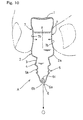
- Figs. 6 through 10 show a modified embodiment of the dent portion 7 formed in the barrel portion 2 of the container body A to be gripped with two fingers.
- This modified dent portion comprises a pair of curved gripping faces 7b which are formed concave respectively at two peripheral portions of the barrel portion, each gripping face being progressively closer to the container axis X as the face extends toward the longitudinal center of the container axis X.
- each gripping face 7b is formed as a mildly curved portion having a curvature smaller than that of the remaining portion of the barrel portion 2 when viewed along the direction of the container axis X. Further, when viewed in the radial direction (viewed from its front) normal to the container axis X direction, the gripping face is curved so that the gripping face comes progressively closer to the container axis X as the face extends toward the longitudinal center of the container axis X.
- the recess 6b in the form of a cone having a bottom and having a progressively increasing inner diameter toward the instilling nozzle 6a and the small instilling nozzle hole 6c which allows control of a solution instilling amount to be pushed out of the container body A in association of a pressing action on the barrel portion 2 with fingers to a predetermined amount.
- the present invention is not limited to such eye drops container. A further construction is possible as shown in Fig.
- a cap B integrally forming a needle-like projection 9 for piercing the instilling nozzle hole at the leading end of the container body A is detachably threaded on a male thread 5a of the container body A made of the flexible thermoplastic resin material and charged and sealed with a predetermined amount of a solution of medicine simultaneously with the blow molding or vacuum molding operation. Then, with a threading operation of the cap B to a position one step deeper than its normal closed position, the needle-like projection 9 of the cap B will form a instilling nozzle hole 6a at the leading end of the container body A.
- the container body A of the eye drops container is formed by the blow molding method or vacuum molding method to obtain an inner nozzle tip function.
- the invention is not limited to the eye drops container having such construction.
- a further construction is shown in Fig. 12, in which an inner nozzle tip 11 formed by the injection molding method is engaged to a cylindrical mouth portion 10 of the container body A.
- Two types of eye drops containers having a dent portion in the barrel portion relating to the present invention and an eye drops container in the form of a hollow cylinder not having such dent portion in the barrel portion relating to a comparison example were prepared and the operability of these eye drops containers was studied with regard to their squeezability.
- An eye drops container made of polyethylene relating to Embodiment 1 has a configuration corresponding to the container body A according to the first mode of embodiment. Specifically, this polyethylene eye drops container relating to Embodiment 1 has a total length of 56.4 mm in its container axis X direction and its liquid outlet 6a has an aperture (aperture diameter) of 2.9 mm. And, its barrel portion 2 is formed as a cylindrical portion with upper end lower ends thereof chamfered, the cylindrical portion having a height of 33.7 mm and a diameter of 19.6 mm.
- a pair of dent portions 7 as recesses having a height H of 19.5 mm, a width W of 13.3 mm and a maximum depth D of 1.6 mm (see Figs. 1 and 2).
- An eye drops container made of polyethylene relating to Embodiment 2 has a configuration corresponding to the container body A according to the second mode of embodiment. Specifically, this polyethylene eye drops container relating to Embodiment 2 has a total length of 56.4 mm in its container axis X direction and its instilling nozzle 6a has an aperture (aperture diameter) of 2.9 mm. And, its barrel portion 2 is formed as a cylindrical portion with upper end lower ends thereof chamfered, the cylindrical portion having a height of 33.7 mm and a diameter of 19.6 mm.
- a pair of dent portions 7 as recesses having a height H of 19.5 mm, a width W of 13.3 mm and a maximum depth D of 1.6 mm (see Figs. 6 and 7).
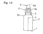
- a conventional eye drops container made of polyethylene relating to the comparison example, as shown in Fig. 13, includes a barrel portion in the form of a hollow cylinder and has an identical construction to Embodiments 1 and 2, except that no dent portion is provided. Therefore, its identical portions of the construction are denoted with the identical reference numerals employed in the first embodiment and description thereof will be omitted.
- These three types of polyethylene eye drops containers are made of a raw material: TOSOH175K (trade name, manufactured by TOSOH Corporation).
- TOSOH175K trade name, manufactured by TOSOH Corporation.
- the raw material was melted and molded so that the containers obtained the weights of 2.0 g, 2.2g and 2.4 g, respectively.
- Each polyethylene eye drops container (specimen) containing water therein was set at a predetermined position on a measuring device, with the solution instilling cylindrical portion 6 thereof being oriented downwards. Then, a chip of the squeezability measuring device was placed against the outer surface center of the dent portion 7 (the barrel portion in the case of the comparison example) of this polyethylene eye drops container.
- the chip was moved toward the axis of the polyethylene eye drops container to press it and the pressing force required for causing a drop of water to be instilled from the instilling nozzle 6a of the polyethylene eye drops container was determined by means of a digital force gauge attached to the measuring device.
- the eye drops container having a dent portion according to the present invention may be used as e.g. an eye drops container for use in instilling a solution of eye medicine for medical treatment.
Landscapes
- Engineering & Computer Science (AREA)
- Health & Medical Sciences (AREA)
- Mechanical Engineering (AREA)
- Life Sciences & Earth Sciences (AREA)
- General Health & Medical Sciences (AREA)
- Fluid Mechanics (AREA)
- Ophthalmology & Optometry (AREA)
- Biomedical Technology (AREA)
- Heart & Thoracic Surgery (AREA)
- Vascular Medicine (AREA)
- Physics & Mathematics (AREA)
- Animal Behavior & Ethology (AREA)
- General Physics & Mathematics (AREA)
- Public Health (AREA)
- Veterinary Medicine (AREA)
- Ceramic Engineering (AREA)
- Medical Preparation Storing Or Oral Administration Devices (AREA)
- Containers Having Bodies Formed In One Piece (AREA)
- Closures For Containers (AREA)
- Stackable Containers (AREA)
- Rigid Containers With Two Or More Constituent Elements (AREA)
Abstract
Description
| pressing force needed for instillation of one drop of water (unit N) | |||
| container weight (g) | | | Comparison example |
| 2.0 | 1.78 | 2.10 | 5.35 |
| 2.2 | 2.39 | 2.60 | 5.93 |
| 2.4 | 3.34 | 3.26 | 6.15 |
Claims (4)
- An eye drops container having a dent portion, wherein the dropper includes a flexible hollow cylindrical barrel portion defining a dent portion which can be gripped with two fingers.
- The eye drops container according to claim 1, wherein the dent portion comprises flat or substantially flat gripping faces which are formed concave respectively at two peripheral portions of the barrel portion.
- The eye drops container according to claim 2, wherein the dent portion comprises curved concave gripping faces which are formed concave respectively at two peripheral portions of the barrel portion, each gripping face being progressively closer to a central axis of the container body as the face extends toward the longitudinal center of the central axis.
- The eye drops container according to claim 1, 2 or 3, wherein the container body having the barrel portion comprises a container body made of thermoplastic resin material which is filled with a solution simultaneously with its forming operation.
Priority Applications (1)
| Application Number | Priority Date | Filing Date | Title |
|---|---|---|---|
| CY20121100468T CY1112976T1 (en) | 1999-08-17 | 2012-05-24 | FITTING ACCESSOR WHICH FORMES INSTALLATION CONTAINER |
Applications Claiming Priority (3)
| Application Number | Priority Date | Filing Date | Title |
|---|---|---|---|
| JP23065299 | 1999-08-17 | ||
| JP23065299 | 1999-08-17 | ||
| PCT/JP2000/005458 WO2001012125A1 (en) | 1999-08-17 | 2000-08-14 | Recessed part forming instillation container |
Publications (3)
| Publication Number | Publication Date |
|---|---|
| EP1213003A1 true EP1213003A1 (en) | 2002-06-12 |
| EP1213003A4 EP1213003A4 (en) | 2009-03-18 |
| EP1213003B1 EP1213003B1 (en) | 2012-04-18 |
Family
ID=16911165
Family Applications (1)
| Application Number | Title | Priority Date | Filing Date |
|---|---|---|---|
| EP00951999A Expired - Lifetime EP1213003B1 (en) | 1999-08-17 | 2000-08-14 | Recessed part forming instillation container |
Country Status (13)
| Country | Link |
|---|---|
| US (1) | US6875201B1 (en) |
| EP (1) | EP1213003B1 (en) |
| KR (1) | KR20020035853A (en) |
| CN (1) | CN1254224C (en) |
| AT (1) | ATE554012T1 (en) |
| AU (1) | AU6477000A (en) |
| CA (1) | CA2380630C (en) |
| CY (1) | CY1112976T1 (en) |
| DK (1) | DK1213003T3 (en) |
| ES (1) | ES2386343T3 (en) |
| PT (1) | PT1213003E (en) |
| TW (1) | TW548224B (en) |
| WO (1) | WO2001012125A1 (en) |
Cited By (7)
| Publication number | Priority date | Publication date | Assignee | Title |
|---|---|---|---|---|
| KR100545842B1 (en) * | 2003-06-23 | 2006-01-31 | 주식회사 대성케미칼 | Eye drop container |
| DE102005056488A1 (en) * | 2005-11-21 | 2007-05-24 | Ing. Erich Pfeiffer Gmbh | Dispenser and dosing unit for medium dosing |
| EP1486192A4 (en) * | 2002-03-18 | 2010-07-14 | Santen Pharmaceutical Co Ltd | INSTILLATOR, STERILIZABLE AT HIGH TEMPERATURE |
| WO2012041614A1 (en) * | 2010-09-28 | 2012-04-05 | Ing. Erich Pfeiffer Gmbh | Discharge device having a compressible media container |
| EP2674224A1 (en) * | 2012-06-15 | 2013-12-18 | Aptar Radolfzell GmbH | Testing device for a liquid dispenser |
| WO2019223922A1 (en) * | 2018-05-23 | 2019-11-28 | F. Holzer Gmbh | Dispensing head and dispensing device for the metered dispensing of liquid preparations, and possible uses |
| RU2778698C2 (en) * | 2018-05-23 | 2022-08-23 | Ф. Хольцер Гмбх | Dispensing head and dispensing device for dosed dispensing of liquid preparations, as well as possible use |
Families Citing this family (24)
| Publication number | Priority date | Publication date | Assignee | Title |
|---|---|---|---|---|
| USD529338S1 (en) * | 2004-03-01 | 2006-10-03 | American Recreation Products, Inc. | Beverage bottle |
| US7198165B2 (en) * | 2004-05-20 | 2007-04-03 | Graham Packaging Pet Technologies Inc. | Molded plastic hot-fill container and method of manufacture |
| JP2009506364A (en) * | 2005-08-31 | 2009-02-12 | ノバルティス アクチエンゲゼルシャフト | Contact lens care products |
| US7527613B2 (en) * | 2006-04-05 | 2009-05-05 | Rush University Medical Center | Therapeutic solution drop dispenser |
| EP2089282B1 (en) * | 2006-12-07 | 2014-01-08 | Sun Pharma Advanced Research Company Ltd | Metered drop bottle for dispensing microliter amounts of a liquid in the form of a drop |
| EP2144663A4 (en) * | 2007-04-06 | 2011-06-22 | Transform Pharmaceuticals Inc | Systems and methods for delivering a fluid drug |
| CA129860S (en) * | 2008-09-19 | 2009-12-14 | Mam Babyartikel | Drinking cup |
| AU325069S (en) * | 2008-09-19 | 2009-03-10 | Mam Babyartikel | Drinking cup |
| BRMU8902988U2 (en) * | 2009-10-14 | 2011-06-14 | Marcos Antonio Quimenton | arrangement applied to dropper applicator |
| US8584311B2 (en) * | 2010-07-07 | 2013-11-19 | Del Lathim | Hand-operable vacuum device |
| EP2697130A1 (en) * | 2011-04-14 | 2014-02-19 | Promed Research Centre | A closure cap for bottle container |
| USD659010S1 (en) | 2011-04-15 | 2012-05-08 | Pepsico, Inc | Bottle |
| CN103054715A (en) * | 2011-10-20 | 2013-04-24 | 苏州市锦新医用塑料容器厂 | Eye drop bottle |
| CN103057822A (en) * | 2011-10-20 | 2013-04-24 | 苏州市锦新医用塑料容器厂 | Liquid holding bottle |
| JP6297056B2 (en) | 2012-11-15 | 2018-03-20 | アムコー グループ ゲーエムベーハー | Pediatric safety tip closure with finger springs |
| US10370161B2 (en) * | 2012-11-15 | 2019-08-06 | Amcor Rigid Plastics Usa, Llc | Child resistant tip closure assembly with diaphragm |
| CN103264807A (en) * | 2013-04-24 | 2013-08-28 | 苏州市锦新医用塑料容器厂 | Liquid medicine bottle less prone to slipping out of hand |
| CA168105S (en) * | 2015-10-30 | 2016-11-30 | Mitsubishi Rayon Cleansui Co | Water purifier |
| JP1555596S (en) * | 2015-10-30 | 2016-08-08 | ||
| JP1555597S (en) * | 2015-10-30 | 2016-08-08 | ||
| JP6586354B2 (en) | 2015-11-20 | 2019-10-02 | 武内プレス工業株式会社 | Squeeze container |
| MX2021009068A (en) * | 2019-01-29 | 2021-08-19 | Amcor Rigid Packaging Usa Llc | Container grip panel with improved side load. |
| FR3093426B1 (en) * | 2019-03-05 | 2022-08-19 | Nemera La Verpilliere | Device for dispensing a solution |
| US20210047078A1 (en) * | 2020-08-18 | 2021-02-18 | Kathryn Anne Moore | Combination closure for facial mask/covering and antimicrobial product |
Family Cites Families (18)
| Publication number | Priority date | Publication date | Assignee | Title |
|---|---|---|---|---|
| US2673661A (en) * | 1949-01-15 | 1954-03-30 | Injection Molding Company | Container |
| US2688424A (en) * | 1950-12-11 | 1954-09-07 | Robert W Keiter | Flexible container for dispensing predetermined quantities of materials |
| US3366284A (en) * | 1966-04-13 | 1968-01-30 | Gen Foods Corp | Liquid metering dispenser container |
| US3552605A (en) * | 1968-09-09 | 1971-01-05 | Lincoln Lab Inc | Drop dispenser with vent |
| JPS58153843U (en) * | 1982-04-08 | 1983-10-14 | ライオン株式会社 | Dripping bottle |
| SE458986B (en) * | 1985-03-29 | 1989-05-29 | Draco Ab | DOSFOERPACKNING |
| US4909801A (en) * | 1986-06-16 | 1990-03-20 | Acorn Laboratories, Inc. | Eyedrop dispenser having a bumper |
| DE3735909A1 (en) * | 1987-10-23 | 1989-05-03 | Hansen Bernd | DRIP BOTTLE AND METHOD FOR THEIR PRODUCTION |
| JPH0425597A (en) | 1990-05-22 | 1992-01-29 | Rasa Kogyo Kk | Detergent for removing soldering flux |
| JPH0544134A (en) | 1991-07-31 | 1993-02-23 | Yamada Dobby Co Ltd | Double negative cam machine |
| JPH0544134U (en) * | 1991-11-25 | 1993-06-15 | 三共株式会社 | Eye drops container |
| JPH0749308B2 (en) * | 1992-04-14 | 1995-05-31 | 積水アイコー株式会社 | One push squeeze type double structure type adhesive packaging container |
| JP2501249Y2 (en) * | 1992-04-21 | 1996-06-12 | 田辺製薬株式会社 | Eye drops container |
| DE4229734A1 (en) * | 1992-09-05 | 1994-03-10 | Henkel Kgaa | Packaging for flowable products |
| US5356052A (en) * | 1993-10-13 | 1994-10-18 | Healthstar Inc. | BFS metered drop bottle |
| CA2176583C (en) * | 1993-12-22 | 2001-11-13 | Arthur L. Lifshey | Ophthalmic package and delivery device |
| US5462200A (en) * | 1994-01-21 | 1995-10-31 | Automatic Liquid Packaging, Inc. | Threaded cap with controlled orifice liner for piercing a sealed container |
| CA2273837C (en) * | 1996-12-09 | 2003-12-30 | Bausch & Lomb Incorporated | Single-use flexible container |
-
2000
- 2000-08-14 US US10/049,694 patent/US6875201B1/en not_active Expired - Lifetime
- 2000-08-14 DK DK00951999.2T patent/DK1213003T3/en active
- 2000-08-14 WO PCT/JP2000/005458 patent/WO2001012125A1/en not_active Ceased
- 2000-08-14 ES ES00951999T patent/ES2386343T3/en not_active Expired - Lifetime
- 2000-08-14 CA CA002380630A patent/CA2380630C/en not_active Expired - Lifetime
- 2000-08-14 PT PT00951999T patent/PT1213003E/en unknown
- 2000-08-14 AU AU64770/00A patent/AU6477000A/en not_active Abandoned
- 2000-08-14 AT AT00951999T patent/ATE554012T1/en active
- 2000-08-14 EP EP00951999A patent/EP1213003B1/en not_active Expired - Lifetime
- 2000-08-14 CN CNB008144443A patent/CN1254224C/en not_active Expired - Lifetime
- 2000-08-14 KR KR1020027001988A patent/KR20020035853A/en not_active Ceased
- 2000-08-16 TW TW089116542A patent/TW548224B/en not_active IP Right Cessation
-
2012
- 2012-05-24 CY CY20121100468T patent/CY1112976T1/en unknown
Cited By (10)
| Publication number | Priority date | Publication date | Assignee | Title |
|---|---|---|---|---|
| EP1486192A4 (en) * | 2002-03-18 | 2010-07-14 | Santen Pharmaceutical Co Ltd | INSTILLATOR, STERILIZABLE AT HIGH TEMPERATURE |
| KR100545842B1 (en) * | 2003-06-23 | 2006-01-31 | 주식회사 대성케미칼 | Eye drop container |
| DE102005056488A1 (en) * | 2005-11-21 | 2007-05-24 | Ing. Erich Pfeiffer Gmbh | Dispenser and dosing unit for medium dosing |
| US7950391B2 (en) | 2005-11-21 | 2011-05-31 | Ing. Erich Pfeiffer Gmbh | Dispenser and dosing subassembly for dosing of a medium |
| WO2012041614A1 (en) * | 2010-09-28 | 2012-04-05 | Ing. Erich Pfeiffer Gmbh | Discharge device having a compressible media container |
| EP2674224A1 (en) * | 2012-06-15 | 2013-12-18 | Aptar Radolfzell GmbH | Testing device for a liquid dispenser |
| WO2019223922A1 (en) * | 2018-05-23 | 2019-11-28 | F. Holzer Gmbh | Dispensing head and dispensing device for the metered dispensing of liquid preparations, and possible uses |
| CN112566849A (en) * | 2018-05-23 | 2021-03-26 | F·霍尔泽股份有限公司 | Dispensing head and dispensing device for metered dispensing of liquid formulations, and potential uses thereof |
| RU2778698C2 (en) * | 2018-05-23 | 2022-08-23 | Ф. Хольцер Гмбх | Dispensing head and dispensing device for dosed dispensing of liquid preparations, as well as possible use |
| US11518571B2 (en) | 2018-05-23 | 2022-12-06 | F. Holzer Gmbh | Dispensing head and dispensing device for the metered dispensing of liquid preparations, and possible uses |
Also Published As
| Publication number | Publication date |
|---|---|
| ATE554012T1 (en) | 2012-05-15 |
| TW548224B (en) | 2003-08-21 |
| CN1379651A (en) | 2002-11-13 |
| CA2380630A1 (en) | 2001-02-22 |
| PT1213003E (en) | 2012-06-18 |
| ES2386343T3 (en) | 2012-08-17 |
| WO2001012125A1 (en) | 2001-02-22 |
| AU6477000A (en) | 2001-03-13 |
| EP1213003A4 (en) | 2009-03-18 |
| CA2380630C (en) | 2007-07-31 |
| EP1213003B1 (en) | 2012-04-18 |
| US6875201B1 (en) | 2005-04-05 |
| DK1213003T3 (en) | 2012-07-16 |
| CN1254224C (en) | 2006-05-03 |
| CY1112976T1 (en) | 2016-04-13 |
| KR20020035853A (en) | 2002-05-15 |
Similar Documents
| Publication | Publication Date | Title |
|---|---|---|
| US6875201B1 (en) | Recessed part forming instillation container | |
| EP0196288B1 (en) | Dosage package | |
| US4230231A (en) | Closure cap | |
| US6361744B1 (en) | Self-resealing closure for containers | |
| CA2178027C (en) | Container for delivery of flowable material | |
| EP1098821B1 (en) | An enclosure cap for multiple piercing | |
| CA2464482C (en) | Eyedropper with step portion | |
| US20110130740A1 (en) | Medication Bottle for Use with Oral Syringe | |
| JP3628242B2 (en) | Recessed part eye drop container | |
| CA2672527A1 (en) | Metered drop bottle for dispensing microliter amounts of a liquid in the form of a drop | |
| TW200951032A (en) | Liquid container | |
| EP0423231B1 (en) | Improved eyedrop dispenser | |
| KR20100022009A (en) | Metering device | |
| US11613399B2 (en) | Container and method of producing container | |
| EP3431070B1 (en) | Drug-filled synthetic resin ampule | |
| US11772851B2 (en) | Liquid applicator | |
| US20050159715A1 (en) | High-temperature-sterilizable instillator | |
| WO2007094243A1 (en) | Container | |
| WO2001008993A1 (en) | Dropper bottle | |
| JPWO2001012125A1 (en) | Eye drop container with recess | |
| EP3919399A1 (en) | Liquid applicator | |
| JP2605070Y2 (en) | Eye drops bottle | |
| JP2002321751A (en) | Container | |
| TW202426353A (en) | Liquid drip container | |
| CN121044168A (en) | Quantitative dispensing container |
Legal Events
| Date | Code | Title | Description |
|---|---|---|---|
| PUAI | Public reference made under article 153(3) epc to a published international application that has entered the european phase |
Free format text: ORIGINAL CODE: 0009012 |
|
| 17P | Request for examination filed |
Effective date: 20020219 |
|
| AK | Designated contracting states |
Kind code of ref document: A1 Designated state(s): AT BE CH CY DE DK ES FI FR GB GR IE IT LI LU MC NL PT SE |
|
| AX | Request for extension of the european patent |
Free format text: AL;LT;LV;MK;RO;SI |
|
| A4 | Supplementary search report drawn up and despatched |
Effective date: 20090218 |
|
| 17Q | First examination report despatched |
Effective date: 20090804 |
|
| REG | Reference to a national code |
Ref country code: DE Ref legal event code: R079 Ref document number: 60047106 Country of ref document: DE Free format text: PREVIOUS MAIN CLASS: A61J0001050000 Ipc: B65D0001320000 |
|
| GRAP | Despatch of communication of intention to grant a patent |
Free format text: ORIGINAL CODE: EPIDOSNIGR1 |
|
| RIC1 | Information provided on ipc code assigned before grant |
Ipc: B65D 1/32 20060101AFI20111020BHEP Ipc: B65D 47/18 20060101ALI20111020BHEP |
|
| GRAS | Grant fee paid |
Free format text: ORIGINAL CODE: EPIDOSNIGR3 |
|
| GRAA | (expected) grant |
Free format text: ORIGINAL CODE: 0009210 |
|
| AK | Designated contracting states |
Kind code of ref document: B1 Designated state(s): AT BE CH CY DE DK ES FI FR GB GR IE IT LI LU MC NL PT SE |
|
| REG | Reference to a national code |
Ref country code: GB Ref legal event code: FG4D |
|
| REG | Reference to a national code |
Ref country code: CH Ref legal event code: EP |
|
| REG | Reference to a national code |
Ref country code: IE Ref legal event code: FG4D |
|
| REG | Reference to a national code |
Ref country code: AT Ref legal event code: REF Ref document number: 554012 Country of ref document: AT Kind code of ref document: T Effective date: 20120515 |
|
| REG | Reference to a national code |
Ref country code: DE Ref legal event code: R096 Ref document number: 60047106 Country of ref document: DE Effective date: 20120614 |
|
| REG | Reference to a national code |
Ref country code: PT Ref legal event code: SC4A Free format text: AVAILABILITY OF NATIONAL TRANSLATION Effective date: 20120606 |
|
| REG | Reference to a national code |
Ref country code: NL Ref legal event code: T3 |
|
| REG | Reference to a national code |
Ref country code: CH Ref legal event code: NV Representative=s name: R. A. EGLI & CO. PATENTANWAELTE |
|
| REG | Reference to a national code |
Ref country code: DK Ref legal event code: T3 |
|
| REG | Reference to a national code |
Ref country code: SE Ref legal event code: TRGR |
|
| REG | Reference to a national code |
Ref country code: ES Ref legal event code: FG2A Ref document number: 2386343 Country of ref document: ES Kind code of ref document: T3 Effective date: 20120817 |
|
| REG | Reference to a national code |
Ref country code: GR Ref legal event code: EP Ref document number: 20120401521 Country of ref document: GR Effective date: 20120903 |
|
| PLBE | No opposition filed within time limit |
Free format text: ORIGINAL CODE: 0009261 |
|
| STAA | Information on the status of an ep patent application or granted ep patent |
Free format text: STATUS: NO OPPOSITION FILED WITHIN TIME LIMIT |
|
| 26N | No opposition filed |
Effective date: 20130121 |
|
| REG | Reference to a national code |
Ref country code: DE Ref legal event code: R097 Ref document number: 60047106 Country of ref document: DE Effective date: 20130121 |
|
| REG | Reference to a national code |
Ref country code: FR Ref legal event code: PLFP Year of fee payment: 17 |
|
| REG | Reference to a national code |
Ref country code: FR Ref legal event code: PLFP Year of fee payment: 18 |
|
| PGFP | Annual fee paid to national office [announced via postgrant information from national office to epo] |
Ref country code: LU Payment date: 20170724 Year of fee payment: 18 |
|
| PGFP | Annual fee paid to national office [announced via postgrant information from national office to epo] |
Ref country code: NL Payment date: 20170712 Year of fee payment: 18 |
|
| PGFP | Annual fee paid to national office [announced via postgrant information from national office to epo] |
Ref country code: IT Payment date: 20170824 Year of fee payment: 18 Ref country code: ES Payment date: 20170906 Year of fee payment: 18 Ref country code: DE Payment date: 20170808 Year of fee payment: 18 Ref country code: CY Payment date: 20170710 Year of fee payment: 18 Ref country code: GR Payment date: 20170711 Year of fee payment: 18 Ref country code: CH Payment date: 20170814 Year of fee payment: 18 Ref country code: FR Payment date: 20170714 Year of fee payment: 18 Ref country code: GB Payment date: 20170809 Year of fee payment: 18 Ref country code: MC Payment date: 20170711 Year of fee payment: 18 Ref country code: FI Payment date: 20170809 Year of fee payment: 18 |
|
| PGFP | Annual fee paid to national office [announced via postgrant information from national office to epo] |
Ref country code: AT Payment date: 20170725 Year of fee payment: 18 Ref country code: DK Payment date: 20170810 Year of fee payment: 18 Ref country code: SE Payment date: 20170810 Year of fee payment: 18 Ref country code: IE Payment date: 20170809 Year of fee payment: 18 Ref country code: BE Payment date: 20170713 Year of fee payment: 18 Ref country code: PT Payment date: 20170804 Year of fee payment: 18 |
|
| REG | Reference to a national code |
Ref country code: DE Ref legal event code: R119 Ref document number: 60047106 Country of ref document: DE |
|
| REG | Reference to a national code |
Ref country code: DK Ref legal event code: EBP Effective date: 20180831 |
|
| PG25 | Lapsed in a contracting state [announced via postgrant information from national office to epo] |
Ref country code: MC Free format text: LAPSE BECAUSE OF NON-PAYMENT OF DUE FEES Effective date: 20180831 |
|
| REG | Reference to a national code |
Ref country code: CH Ref legal event code: PL |
|
| REG | Reference to a national code |
Ref country code: SE Ref legal event code: EUG |
|
| REG | Reference to a national code |
Ref country code: NL Ref legal event code: MM Effective date: 20180901 |
|
| REG | Reference to a national code |
Ref country code: AT Ref legal event code: MM01 Ref document number: 554012 Country of ref document: AT Kind code of ref document: T Effective date: 20180814 |
|
| GBPC | Gb: european patent ceased through non-payment of renewal fee |
Effective date: 20180814 |
|
| PG25 | Lapsed in a contracting state [announced via postgrant information from national office to epo] |
Ref country code: CH Free format text: LAPSE BECAUSE OF NON-PAYMENT OF DUE FEES Effective date: 20180831 Ref country code: AT Free format text: LAPSE BECAUSE OF NON-PAYMENT OF DUE FEES Effective date: 20180814 Ref country code: FI Free format text: LAPSE BECAUSE OF NON-PAYMENT OF DUE FEES Effective date: 20180814 Ref country code: LU Free format text: LAPSE BECAUSE OF NON-PAYMENT OF DUE FEES Effective date: 20180814 Ref country code: LI Free format text: LAPSE BECAUSE OF NON-PAYMENT OF DUE FEES Effective date: 20180831 Ref country code: CY Free format text: LAPSE BECAUSE OF NON-PAYMENT OF DUE FEES Effective date: 20180814 |
|
| REG | Reference to a national code |
Ref country code: BE Ref legal event code: MM Effective date: 20180831 |
|
| REG | Reference to a national code |
Ref country code: IE Ref legal event code: MM4A |
|
| PG25 | Lapsed in a contracting state [announced via postgrant information from national office to epo] |
Ref country code: SE Free format text: LAPSE BECAUSE OF NON-PAYMENT OF DUE FEES Effective date: 20180815 Ref country code: GR Free format text: LAPSE BECAUSE OF NON-PAYMENT OF DUE FEES Effective date: 20190307 Ref country code: PT Free format text: LAPSE BECAUSE OF NON-PAYMENT OF DUE FEES Effective date: 20190214 |
|
| PG25 | Lapsed in a contracting state [announced via postgrant information from national office to epo] |
Ref country code: NL Free format text: LAPSE BECAUSE OF NON-PAYMENT OF DUE FEES Effective date: 20180901 |
|
| PG25 | Lapsed in a contracting state [announced via postgrant information from national office to epo] |
Ref country code: DK Free format text: LAPSE BECAUSE OF NON-PAYMENT OF DUE FEES Effective date: 20180831 Ref country code: DE Free format text: LAPSE BECAUSE OF NON-PAYMENT OF DUE FEES Effective date: 20190301 Ref country code: IT Free format text: LAPSE BECAUSE OF NON-PAYMENT OF DUE FEES Effective date: 20180814 Ref country code: IE Free format text: LAPSE BECAUSE OF NON-PAYMENT OF DUE FEES Effective date: 20180814 |
|
| PG25 | Lapsed in a contracting state [announced via postgrant information from national office to epo] |
Ref country code: FR Free format text: LAPSE BECAUSE OF NON-PAYMENT OF DUE FEES Effective date: 20180831 Ref country code: BE Free format text: LAPSE BECAUSE OF NON-PAYMENT OF DUE FEES Effective date: 20180831 |
|
| REG | Reference to a national code |
Ref country code: ES Ref legal event code: FD2A Effective date: 20190918 |
|
| PG25 | Lapsed in a contracting state [announced via postgrant information from national office to epo] |
Ref country code: ES Free format text: LAPSE BECAUSE OF NON-PAYMENT OF DUE FEES Effective date: 20180815 Ref country code: GB Free format text: LAPSE BECAUSE OF NON-PAYMENT OF DUE FEES Effective date: 20180814 |