EP1212928B1 - Wärmeleitende vorrichtung für eine leiterplatte - Google Patents
Wärmeleitende vorrichtung für eine leiterplatte Download PDFInfo
- Publication number
- EP1212928B1 EP1212928B1 EP00959421A EP00959421A EP1212928B1 EP 1212928 B1 EP1212928 B1 EP 1212928B1 EP 00959421 A EP00959421 A EP 00959421A EP 00959421 A EP00959421 A EP 00959421A EP 1212928 B1 EP1212928 B1 EP 1212928B1
- Authority
- EP
- European Patent Office
- Prior art keywords
- collar
- airframe
- heat conducting
- thermal
- assembly
- Prior art date
- Legal status (The legal status is an assumption and is not a legal conclusion. Google has not performed a legal analysis and makes no representation as to the accuracy of the status listed.)
- Expired - Lifetime
Links
- 238000000034 method Methods 0.000 claims description 7
- 230000033001 locomotion Effects 0.000 description 10
- 230000004941 influx Effects 0.000 description 6
- 238000003780 insertion Methods 0.000 description 6
- 230000037431 insertion Effects 0.000 description 6
- 230000008878 coupling Effects 0.000 description 3
- 238000010168 coupling process Methods 0.000 description 3
- 238000005859 coupling reaction Methods 0.000 description 3
- 238000013461 design Methods 0.000 description 3
- 230000004075 alteration Effects 0.000 description 2
- 230000007246 mechanism Effects 0.000 description 2
- 238000012986 modification Methods 0.000 description 2
- 230000004048 modification Effects 0.000 description 2
- 238000000844 transformation Methods 0.000 description 2
- 230000009466 transformation Effects 0.000 description 2
- RYGMFSIKBFXOCR-UHFFFAOYSA-N Copper Chemical compound [Cu] RYGMFSIKBFXOCR-UHFFFAOYSA-N 0.000 description 1
- 229910052782 aluminium Inorganic materials 0.000 description 1
- XAGFODPZIPBFFR-UHFFFAOYSA-N aluminium Chemical compound [Al] XAGFODPZIPBFFR-UHFFFAOYSA-N 0.000 description 1
- 239000002131 composite material Substances 0.000 description 1
- 230000008602 contraction Effects 0.000 description 1
- 238000001816 cooling Methods 0.000 description 1
- 229910052802 copper Inorganic materials 0.000 description 1
- 239000010949 copper Substances 0.000 description 1
- 230000007423 decrease Effects 0.000 description 1
- 239000011152 fibreglass Substances 0.000 description 1
- 230000010006 flight Effects 0.000 description 1
- 238000010438 heat treatment Methods 0.000 description 1
- 238000009434 installation Methods 0.000 description 1
- 230000003993 interaction Effects 0.000 description 1
- 239000007788 liquid Substances 0.000 description 1
- 229910052751 metal Inorganic materials 0.000 description 1
- 239000002184 metal Substances 0.000 description 1
- 239000012782 phase change material Substances 0.000 description 1
- 239000004033 plastic Substances 0.000 description 1
- 239000000758 substrate Substances 0.000 description 1
- 238000012546 transfer Methods 0.000 description 1
Images



Classifications
-
- H—ELECTRICITY
- H05—ELECTRIC TECHNIQUES NOT OTHERWISE PROVIDED FOR
- H05K—PRINTED CIRCUITS; CASINGS OR CONSTRUCTIONAL DETAILS OF ELECTRIC APPARATUS; MANUFACTURE OF ASSEMBLAGES OF ELECTRICAL COMPONENTS
- H05K7/00—Constructional details common to different types of electric apparatus
- H05K7/20—Modifications to facilitate cooling, ventilating, or heating
- H05K7/2039—Modifications to facilitate cooling, ventilating, or heating characterised by the heat transfer by conduction from the heat generating element to a dissipating body
- H05K7/20436—Inner thermal coupling elements in heat dissipating housings, e.g. protrusions or depressions integrally formed in the housing
- H05K7/20445—Inner thermal coupling elements in heat dissipating housings, e.g. protrusions or depressions integrally formed in the housing the coupling element being an additional piece, e.g. thermal standoff
-
- F—MECHANICAL ENGINEERING; LIGHTING; HEATING; WEAPONS; BLASTING
- F42—AMMUNITION; BLASTING
- F42B—EXPLOSIVE CHARGES, e.g. FOR BLASTING, FIREWORKS, AMMUNITION
- F42B15/00—Self-propelled projectiles or missiles, e.g. rockets; Guided missiles
- F42B15/08—Self-propelled projectiles or missiles, e.g. rockets; Guided missiles for carrying measuring instruments; Arrangements for mounting sensitive cargo within a projectile; Arrangements for acoustic sensitive cargo within a projectile
-
- F—MECHANICAL ENGINEERING; LIGHTING; HEATING; WEAPONS; BLASTING
- F42—AMMUNITION; BLASTING
- F42B—EXPLOSIVE CHARGES, e.g. FOR BLASTING, FIREWORKS, AMMUNITION
- F42B15/00—Self-propelled projectiles or missiles, e.g. rockets; Guided missiles
- F42B15/34—Protection against overheating or radiation, e.g. heat shields; Additional cooling arrangements
-
- H—ELECTRICITY
- H05—ELECTRIC TECHNIQUES NOT OTHERWISE PROVIDED FOR
- H05K—PRINTED CIRCUITS; CASINGS OR CONSTRUCTIONAL DETAILS OF ELECTRIC APPARATUS; MANUFACTURE OF ASSEMBLAGES OF ELECTRICAL COMPONENTS
- H05K7/00—Constructional details common to different types of electric apparatus
- H05K7/14—Mounting supporting structure in casing or on frame or rack
- H05K7/1422—Printed circuit boards receptacles, e.g. stacked structures, electronic circuit modules or box like frames
- H05K7/1427—Housings
- H05K7/1434—Housings for electronics exposed to high gravitational force; Cylindrical housings
Definitions
- This invention relates to heat conducting devices, and more particularly to a heat conducting device for a circuit board.
- a circuit board (CB) located in a missile contains electronics mounted on and through the CB.
- the electronics themselves generate heat, and the CB may also experience an influx of aerodynamic heat through the airframe of the missile during high speed flight. Both internal and external sources of heat may degrade the operation of the CB and the electronics.
- the present invention substantially reduces or eliminates at least some of the disadvantages and problems associated with circuit boards (CBs) in missiles.
- the present invention can provide a heat conducting device with a low impedance thermal path for the heat generated by the electronics on the CB in one mode of operation of the missile and a high impedance thermal path for the heat generated by the aerodynamics on the airframe in another mode of operation of the missile.
- a heat conducting device for providing a thermal path between a circuit board and an airframe includes a thermal plane adapted to receive a circuit board and a collar encompassing at least a portion of the thermal plane.
- the collar has a first position to disengage from at least a portion of the airframe and a second position to engage at least a portion of the airframe to provide a thermal path between the circuit board and the airframe.
- a method for providing a thermal path between a circuit board and an airframe includes mounting a circuit board on a thermal plane and disposing a collar around at least a portion of the thermal plane. The method also includes placing the collar in a first position to disengage from at least a portion of the airframe and placing the collar in a second position to engage at least a portion of the airframe to provide a thermal path between the circuit board and the airframe.
- the present invention has several important technical features and advantages.
- Second, the collar and, hence, the heat conducting device engaging with at least a portion of the airframe when the collar is in the engaged position provides a low impedance thermal path between the CB and the airframe for the heat generated by the electronics on the CB during one mode of operation of a missile, such as during captive flight of an air-to-air missile.
- the heat conducts through the thermal plane and the collar to the airframe, where it discharges to the ambient surroundings.
- the collar can again be placed in the disengaged position, which raises the impedance of the thermal path between the CB and the airframe during another mode of operation of a missile, such as high speed free flight of an air-to-air missile. This protects the CB and the electronics from influxing aerodynamic heat.
- the thermal plane has a shape similar to a lateral cross-section of the missile, allowing the CB and the thermal plane to mount perpendicular to the longitudinal axis of the missile. This shape allows for a more uniform design of the heat conducting devices and the CBs and provides a more structurally sound support for the CBs, compared to CB mountings parallel to the longitudinal axis of the missile.
- multiple heat conducting devices can couple together to form an assembly of heat conducting devices before insertion into a missile, during assembly or when the electronics are being repaired and reinstalled. This permits efficient interconnection between the electronics on CBs on different heat conducting devices in the assembly.
- placing the collars in the disengaged position allows for efficient insertion of the heat conducting devices in the assembly into the missile.
- placing the collars, individually or as a group, in the engaged position engages them with at least a portion of the airframe, providing a low impedance thermal path for the heat generated by the electronics on the CBs during one mode of operation of a missile.
- an actuator disengages all of the collars in the assembly from at least a portion of the airframe during another mode of operation of a missile.
- the heat conducting devices in the assembly can move laterally to the longitudinal axis of the missile independently of each other when the collars are disengaged.
- the heat conducting devices can independently center when engaging the airframe.
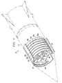
- FIGURE 1 shows an assembly 20 of heat conducting devices 30a, 30b, 30c, 30d, 30e, 30f, and 30g (generally referred to as heat conducting device 30) mounted in a missile 10.
- assembly 20 may have any number of heat conducting devices 30.
- a circuit board (CB) 80 mounts onto heat conducting device 30 and contains a variety of electronic devices 82, which could include integrated circuits, microprocessors, active radar components, or any other type of electronic device.
- CB 80 can be a printed circuit board, a printed wafer board, or any other substrate on which electronic devices 82 may be mounted and/or interconnected.
- CB 80 can be composed of plastic, fiberglass, or composite. In a particular embodiment, CB 80 is composed of FR-4.
- Heat conducting device 30 can disengage from airframe 12 of missile 10 and can engage with airframe 12 of missile 10.
- heat conducting device 30 provides a high impedance thermal path between CB 80 and airframe 12 for heat from airframe 12 of missile 10, but by engaging with airframe 12, heat conducting device 30 provides a low impedance thermal path between CB 80 and airframe 12 for heat generated by electronic devices 82 on CB 80.
- Airframe 12 can be the skin of missile 10, a spar of missile 10, a bulkhead of missile 10, or any other structural component of missile 10 that provides a thermal path to transfer heat generated by heat conducting device 30.
- heat conducting device 30 is in the disengaged mode, which contracts its outside perimeter, during insertion into missile 10. After insertion and mounting, heat conducting device 30 expands to engage airframe 12 of missile 10. Engaging airframe 12 provides a low impedance thermal path for transferring the heat generated by electronic devices 82 on CB 80 to airframe 12, where it discharges to the ambient surroundings, such as the atmosphere, during certain modes of operation of missile 10. For other modes of operation of missile 10, heat conducting device 30 disengages from airframe 12, by contracting again, to insulate CB 80 from heat, such as aerodynamic heat, on airframe 12. Each heat conducting device 30 in assembly 20 can expand and contract to engage and disengage, respectively, with airframe 12.
- heat conducting device 30 has a shape similar to a lateral cross-section of airframe 12. This allows for a uniform design for heat conducting device 30 and/or CB 80. Also, this shape allows heat conducting device 30 to mount perpendicular to the longitudinal axis of airframe 12, which provides a sound structural support for CB 80.
- Heat conducting device 30 is particularly useful in air-to-air missiles, where there are long periods during which missile 10 is attached to an aircraft, so called “captive flight,” usually at relative low flight speeds, and short periods during which missile 10 is flying under its own power, so called “free flight,” usually at relatively high flight speeds.
- electronic devices 82 can be active in both operational modes of missile 10, thereby producing heat
- engaging heat conducting device 30 with airframe 12 during captive flight allows the heat generated by electronic devices 30 to discharge to the atmosphere.
- disengaging heat conducting device 30 from airframe 12 during free flight allows CB 80 and electronic devices 82 to be protected from influxing aerodynamic heat during the relatively short free flight.
- the mass of heat conducting device 30 assists in providing this protection by absorbing sufficient heat to ensure that the electronic devices 82 on CB 80 do not have excessive temperatures.
- FIGURE 2 shows an exploded view of heat conducting device 30 and CB 80.
- heat conducting device 30 includes a collar 32 and a thermal plane 36.
- Collar 32 encompasses at least a portion of thermal plane 36 and possesses a series of notches 35 and a tapered inside perimeter 33.
- Thermal plane 36 includes a tapered outside perimeter 39 that corresponds to tapered inside perimeter 33 of collar 32.
- Thermal plane 36 also includes apertures 42 and tensioners 48 in apertures 42. Tensioners 48 engage collar 32 in notches 35.
- Collar 32 and thermal plane 36 may be composed of aluminum, copper, or any other metal that possesses a good thermal conductivity.
- CB 80 mounts onto thermal plane 36. In certain embodiments, two CBs 80 may mount on thermal plane 36, one on either side.
- tensioners 48 in apertures 42 of thermal plane 36 engage collar 32 in notches 35.
- collar 32 moves between the disengaged and engaged positions, disengaging and engaging heat conducting device 30 with airframe 12 of missile 10.
- collar 32 does not require continuous contact with airframe 12 to engage airframe 12, and thus, collar 32 may only contact airframe 12 at a discrete number of points and still provide a low impedance thermal path between CB 80 and airframe 12.
- collar 32 may continue to contact airframe 12 at a discrete number of points and still provide a high impedance thermal path.
- collar 32 may sometimes disengage from thermal plane 36 and remain engaged with airframe 12 when moved into the disengaged position. Thus, when moved back into the engaged position, collar 32 will engage with thermal plane 36. Additionally, collar 32 may sometimes disengage from thermal plane 36 and airframe 12 when moved into the disengaged position. Thus, when moved back into the engaged position, collar 32 will engage thermal plane 36 and airframe 12. When collar 32 disengages in either of these manners, however, heat conducting device 30 still provides a high impedance thermal path between airframe 12 and circuit board 80.
- FIGURE 3 shows a top view of thermal plane 36 and collar 32 of heat conducting device 30.
- Thermal plane 36 contains a generally level surface 38 upon which CB 80 (not shown) mounts and a ridge 40 that forms the perimeter of thermal plane 36.
- Ridge 40 protects electronic devices 82 on CB 80 from an adjacent heat conducting device 30 in assembly 20, provides mounting boundaries for CB 80, enhances structural rigidity of heat conducting device 30, and gives tapered outside perimeter 39 enough depth to accommodate the movements of collar 32.
- ridge 40 and collar 32 are truncated, forming an aperture 37 in heat conducting device 30.
- Aperture 37 provides a path for couplers between CB 80 and other CBs 80 on heat conducting devices 30 in assembly 20.
- structural supports can couple to heat conducting device 30 through aperture 37.
- Ridge 40 also contains apertures 42, which contain tensioners 48 (not shown), and apertures 41, used in coupling heat conducting device 30 to other heat conducting devices 30 in assembly 20.
- One of apertures 42 is shown with a screw 60 inserted, and one of apertures 42 is shown with an actuator 65 inserted. Screw 60 and actuator 65 are representative of actuation devices that can actuate tensioners 48 in apertures 42, disengaging and engaging collar 32.
- FIGURE 4A provides a cut-away view of thermal plane 36 and collar 32 along section line 4-4 with screw 60 extracted from thermal plane 36.
- thermal plane 36 also includes threads 43, a plunger 44, a spring 46, and a retainer 50 in each aperture 42.
- Plunger 44 has a head 45 at one end and extends through an aperture in spring 46, tensioner 48, and retainer 50.
- the end of plunger 44 opposite head 45 can engage plunger 44 in an adjacent heat conducting device 30 in assembly 20.
- Plunger 44 engages tensioner 48 by means of head 45.
- Tensioner 48 in turn engages collar 32 in notches 35 in collar 32.
- Tensioner 48 also engages spring 46, which is held in place on one end by retainer 50.
- Spring 46 may be a coiled spring, a flexible lever, or any other device that provides a restorative force to tensioner 48. In certain embodiments, spring 46 may compensate for temperature.
- Collar 32 is engaged with at least a portion of airframe 12 in the absence of forces applied by an actuating device.
- spring 46 moves tensioner 48 toward threads 43, which in turn moves collar 32 substantially perpendicular to thermal plane 36, as indicated by arrow 47.
- the perimeter of heat conducting device 30 expands to engage at least a portion of airframe 12 (not shown) of missile 10 when no force is applied by an actuating device, creating a low impedance thermal path for transferring heat generated by electronic devices 82 on CB 80 to the ambient surroundings.
- FIGURE 4B provides a cut-away view of thermal plane 36 and collar 32 along section line 4-4 with screw 60 inserted into thermal plane 36.
- Screw 60 can serve as an actuating device to disengage and engage collar 32 with airframe 12.
- screw 60 inserts into aperture 42 and engages threads 43 and, subsequently, plunger 44, which engages tensioner 48.
- plunger 44 which engages tensioner 48.
- tensioner 48 moves, it compresses spring 46 and moves collar 32 substantially perpendicular to thermal plane 36, as indicated by arrow 47, due to the engagement with collar 32 in notches 35.
- tensioner 48 may extend into more or fewer notches 35 in collar 32.
- heat conducting device 30 contracts due to the interaction of tapered inside perimeter 33 of collar 32 with tapered outside perimeter 39 of thermal plane 36.
- heat conducting device 30 disengages from at least a portion of airframe 12 (not shown).
- the disengagement creates a high impedance thermal path for heat from airframe 12, as an air gap forms between at least portions of collar 32 and airframe 12.
- This high impedance thermal path between airframe 12 and CB 80 impedes the influx of heat to CB 80 during high speed flight, or in any other mode of operation of missile 10 in which heat influxes from airframe 12.
- the contraction also provides an efficient way to insert heat conducting device 30 into missile 10.
- thermal plane 36 could also include a phase change material to assist in impeding the influx of heat from airframe 12 during free flight.
- missile 10 could also use active cooling, e.g., a circulated or expended liquid.
- FIGURE 5A provides a cut-away view of thermal plane 36 and collar 32 along section line 5-5 with actuator 65 used as the actuation device.
- actuator 65 is a pneumatic actuator, which includes a cavity 66, a plunger 67, and a spring 68.
- actuator 65 could also be an electrical solenoid, a motorized screw, a preloaded spring plunger assembly that is released by an electrically initiated pyrotechnic element, or any other mechanized device that can move plunger 44.
- Actuator 65 is shown disengaged in FIGURE 5A, meaning that collar 32 is engaged with airframe 12 (not shown).
- spring 68 moves plunger 67, which forces air out of cavity 66.
- the movement of plunger 67 by spring 68 disengages plunger 67 from plunger 44 of thermal plane 36, which allows spring 46 to move tensioner 48 toward actuator 65.
- Tensioner 48 correspondingly moves collar 32, which expands the perimeter of heat conducting device 30.
- head 45 of plunger 44 floats freely between ridge 40 and tensioner 48 when actuator 65 is disengaged because the ends of plunger 44 are not connected to anything. This allows collar 32 to compensate for variations in airframe 12.
- FIGURE 5B provides a cut-away view of thermal plane 36 and collar 32 along section line 5-5 with actuator 65 engaged.
- Actuator 65 engages by having air pumped into cavity 66. This forces plunger 67 to move spring 68 and plunger 44. Plunger 44 in turn moves tensioner 48, which moves collar 32.
- actuator 65 engages thermal plane 36, collar 32 disengages from at least a portion of airframe 12 of missile 10.
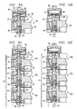
- FIGURE 6A provides a cut-away view of assembly 20 of heat conducting devices 30 along section line 5-5 with actuator 65 used as the actuation device.
- actuator 65 is again a pneumatic actuator and can disengage and engage collar 32 for each heat conducting device 30a-30g with at least a portion of airframe 12.
- actuator 65 is disengaged.
- spring 68 moves plunger 67, away from plunger 44 of heat conducting device 30a.
- this allows spring 46 of heat conducting device 30a to move tensioner 48 of heat conducting device 30a, which in turn moves collar 32 of heat conducting device 30a.
- this sequence also occurs for plunger 44, spring 46, tensioner 48, and collar 32 in heat conducting devices 30b-30g in assembly 20, allowing collar 32 of each heat conducting device 30b-30g to engage airframe 12 of missile 10.
- actuator 65 disengages each heat conducting device 30a-30g engages airframe 12.
- each heat conducting device 30a-30g can independently engage airframe 12 of missile 10 because each tensioner 48 does not affect any other tensioner 48. This allows each heat conducting device 30a-30g to independently compensate for variations of airframe 12.
- FIGURE 6B provides a cut-away view of assembly 20 of heat conducting devices 30 along section line 5-5 with actuator 65 engaged.
- engaging actuator 65 moves plunger 67 of actuator 65, moving plunger 44 of heat conducting device 30a. And again, this moves tensioner 48 and collar 32 of heat conducting device 30a.
- plunger 44 of heat conducting device 30a also moves plunger 44 of heat conducting device 30b, which in turn moves plunger 44 of heat conducting device 30c, and so forth. Movement of plunger 44 of each heat conducting device 30b-30g moves tensioner 48 of each conducting device 30b-30g, which in turn moves collar 32 of each heat conducting device 30b-30g.
- actuator 65 can engage and disengage assembly 20 of heat conducting devices 30a-30g with airframe 12 of missile 10 by disengaging and engaging plunger 44 of heat conducting device 30a.
- actuator 65 is shown as actuating all of heat conducting devices 30a-30g in assembly 20 simultaneously, a variety of other actuation devices exist that can actuate all of heat conducting devices 30a-30g in assembly 20 simultaneously.
- screw 60 in FIGURE 4B can actuate all of heat conducting devices 30 in assembly 20 simultaneously.
- any of the previously discussed variations of actuator 65 can perform the same function.
- an actuation device that can simultaneously actuate all of heat conducting devices 30a-30g in assembly 20 can be any device that can move plunger 44 of heat conducting device 30a substantially perpendicular to thermal plane 36.
- FIGURE 7A illustrates another embodiment that can actuate collar 32.
- the actuation device in this embodiment is similar to the ones in the previously discussed embodiments, except that each tensioner 48 engages collar 32 in one notch 35 in collar 32.
- a cam 52 rather than plunger 44, moves tensioner 48.
- Cam 52 possesses gear teeth around its largest outside diameter, which may be engaged in aperture 42 by an actuation device as described below.
- tensioner 48 possesses a slanted surface 49 along which cam 52 engages tensioner 48.
- Cam 52 has a slanted surface 53 that corresponds to slanted surface 49 of tensioner 48.
- the embodiment further includes an additional retainer 51, which retains one end of cam 52.
- FIGURE 7B illustrates the actuation of collar 32 for this embodiment.
- a tool 54 serves as the actuation device.
- Tool 54 actuates collar 32 by engaging cam 52 in aperture 42.
- Tool 54 includes a shaft 55 that has a set of gear teeth 56 on a certain portion.
- tool 54 inserts into aperture 42 until gear teeth 56 mesh with corresponding gear teeth of cam 52.
- cam 52 rotates.
- gear teeth 56 mesh with corresponding gear teeth of cam 52.
- shaft 55 rotates around its longitudinal axis
- cam 52 rotates.
- retainer 51 engages retainer 51 and then begins to move tensioner 48 toward retainer 50, which compresses spring 46.
- tool 54 has rotated cam 52 to achieve the maximum movement of tensioner 48 toward retainer 50 by cam 52.
- the movement of tensioner 48 allows collar 32 to move along tapered outside perimeter 39 of thermal plane 36 toward retainer 50, which decreases the perimeter of heat conducting device 30, disengaging collar 32 from airframe 12.
- shaft 55 of tool 54 is long enough so that gear teeth 56 can extend through an associated aperture 42 of each heat conducting device 30 in assembly 20.
- tool 54 can actuate each cam 52 of each heat conducting device 30 in assembly 20 after installation of assembly 20 in missile 10.
- collar 32 and heat conducting device 36 would not require tapered inside perimeter 33 and tapered outside perimeter 39, respectively, to expand and contract the outer perimeter of heat conducting device 30.
- the outer perimeter can be expanded other than by moving collar 32 along tapered outside perimeter 39. This can be accomplished, for example, by pistons that can engage collar 32 with airframe 12 by pushing collar 32 away from the center of thermal plane 36.
- thermal plane 36 and collar 32 would not necessarily have tapered outside perimeter 39 and tapered inside perimeter 33, respectively.
- assembly 20 contemplates any suitable mechanisms, and associated configurations of collar 32 and thermal plane 36, that can engage collar 32 to expand the perimeter of heat conducting device 30.
- FIGURE 8 provides a cut-away view of assembly 20 of heat conducting devices 30a-30g along section line 7-7 that illustrates a fastener assembly 72 for coupling heat conducting devices 30a-30g in assembly 20 together.
- Fastener assembly 72 includes e-clips 74 and an elongated member 73, which extends through apertures 41 in heat conducting devices 30a-30g.
- E-clips 74 fit into grooves machined in elongated member 73, capturing elongated member 73 on either side of each heat conducting device 30a-30g.
- Fastener assembly 72 maintains minimum spacing requirements between each heat conducting device 30a-30g while allowing each heat conducting device 30a-30g to have some movement independent of other heat conducting devices 30 in assembly 20. Independent lateral movement allows each heat conducting device 30a-30g to independently center in missile 10 while engaging with airframe 12 of missile 10.
- elongated member 73 is a rod with threads formed at one of its ends. The threads allow elongated member 73, and hence assembly 20, to mount to a bulkhead of missile 10.
- assembly 20 can mount to missile 10 by struts, spars, or any other structural support.
- fastener assembly 72 can be shafts on each heat conducting device 30 that lock into chambers on adjacent heat conducting devices 30, corresponding tabs and locking slots on each heat conducting device 30, or any other device that will allow a plurality of heat conducting devices 30 to couple together to form assembly 20.
- heat conducting device 30 has been described, at least in part, with respect to missiles, and in particular air-to-air missiles, e.g., captive flight and free flight.
- heat conducting device 30, or assembly 20 could also be useful in other aircraft/spacecraft, such as surface-to-air missiles, air-to-surface missiles, reentry vehicles, satellites, or any other vehicle that possesses electronics from which heat must be dissipated and that experiences varying external thermal loading from which the electronics must be protected.
Landscapes
- Engineering & Computer Science (AREA)
- Microelectronics & Electronic Packaging (AREA)
- Chemical & Material Sciences (AREA)
- Aviation & Aerospace Engineering (AREA)
- Combustion & Propulsion (AREA)
- General Engineering & Computer Science (AREA)
- Physics & Mathematics (AREA)
- Thermal Sciences (AREA)
- Cooling Or The Like Of Electrical Apparatus (AREA)
- Aiming, Guidance, Guns With A Light Source, Armor, Camouflage, And Targets (AREA)
- Connection Of Plates (AREA)
Claims (17)
- Wärmeleitende Vorrichtung (30) zum Bereitstellen eines einstellbaren Wärmepfads zwischen einer Leiterplatte (80) und einer Flugzelle (12) mit:einer Thermoplatte (36) zur Aufnahme einer Leiterplatte (80);einem Einfassungsteil (32), das zumindest einen Teil der Thermoplatte umfasst, wobei das Einfassungsteil zwischen einer ersten Position, die von zumindest einem Teil der Flugzelle abgelöst ist, um einen Pfad mit einem hohen thermischen Widerstand zwischen der Leiterplatte und der Flugzelle bereitzustellen, und einer zweiten Position einstellbar ist, bei der zumindest ein Teil der Flugzelle angekoppelt ist, um einen thermischen Pfad zwischen der Leiterplatte und der Flugzelle herzustellen;einer Betätigungsvorrichtung (60,65), mit der die Thermoplatte und das Einfassungsteil gekoppelt werden, um das Einfassungsteil zwischen der ersten Position und der zweiten Position einzustellen.
- Wärmeleitende Vorrichtung nach Anspruch 1, wobei die Thermoplatte (36) eine konische äußere Begrenzungsfläche aufweist und das Einfassungsteil (32) eine konische innere Begrenzungsfläche aufweist.
- Wärmeleitende Vorrichtung nach Anspruch 1, wobei die Betätigungsvorrichtung desweiteren eine Vielzahl von Spannelementen (48) umfasst, mit denen das Einfassungsteil hauptsächlich senkrecht zur Thermoplatte bewegbar ist.
- Wärmeleitende Vorrichtung nach Anspruch 1, wobei die Betätigungsvorrichtung ein pneumatisches Stellglied (65) umfasst.
- Wärmeleitende Vorrichtung nach Anspruch 1, wobei die Flugzelle (12) die Flugzelle einer Rakete umfasst, und die Betätigungsvorrichtung betätigt wird, um das Einfassungsteil (32) in die erste Position bei einem freien Flug der Rakete zu bringen.
- Verfahren zum Herstellen eines einstellbaren Wärmepfads zwischen einer Leiterplatte (80) und einer Flugzelle (12) mit folgenden Schritten:Befestigen einer Leiterplatte (80) auf eine Thermoplatte (36);Positionieren eines Einfassungsteils (32) rund um zumindest einen Teil der Thermoplatte;Einstellen des Einfassungsteils in eine erste Position, die losgelöst von zumindest einem Teil der Flugzelle ist, um einen Wärmepfad mit einem hohen Wärmewiderstand zwischen der Leiterplatte und der Flugzelle bereit zu stellen;Einstellen des Einfassungsteils in eine zweite Position, in der zumindest ein Teil der Flugzelle angekoppelt wird, um einen thermischen Pfad zwischen der Leiterplatte und der Flugzelle bereitzustellen.
- Verfahren nach Anspruch 6, wobei das Einstellen des Einfassungsteils ein Bewegen des Einfassungsteils hauptsächlich senkrecht zu der Thermoplatte umfasst.
- Verfahren nach Anspruch 6, wobei die Thermoplatte eine konische äußere Begrenzungsfläche umfasst und das Einfassungsteil eine konische innere Begrenzungsfläche umfasst.
- Verfahren nach Anspruch 6, welches als weiteren Schritt das Befestigen der Thermoplatte in der Flugzelle nach Einstellen des Einfassungsteils in die erste Position vor dem Einstellen des Einfassungsteils in die zweite Position umfasst.
- Verfahren nach Anspruch 6, wobei ein weiterer Verfahrensschritt das Einstellen des Einfassungsteils in die erste Position für einen freien Flug umfasst.
- Anordnung zum Bereitstellen eines einstellbaren thermischen Pfads zwischen einer Vielzahl von Leiterplatten (80) und einer Flugzelle (12) mit:einer Vielzahl von wärmeleitenden Vorrichtungen (30), wobei jede wärmeleitende Vorrichtung umfasst:eine Thermoplatte (36) zur Aufnahme einer Leiterplatte (80);ein Einfassungsteil (32), das zumindest einen Teil der Thermoplatte umfasst, wobei das Einfassungsteil zwischen einer ersten Position, die losgelöst von zumindest einem Teil der Flugzelle ist, um einen thermischen Pfad mit einem hohen Wärmewiderstand zwischen der Leiterplatte und der Flugzelle bereitzustellen, und einer zweiten Position, bei der zumindest ein Teil der Flugzelle angekoppelt wird, einstellbar ist;einer Betätigungsvorrichtung (60, 65), welche die Thermoplatte und das Einfassungsteil betätigt, um das Einfassungsteil zwischen der ersten Position und der zweiten Position einzustellen;einen Befestigungsaufbau (72), um die wärmeleitenden Vorrichtungen untereinander zu koppeln.
- Anordnung nach Anspruch 11, wobei die Betätigungsvorrichtung jeder einzelnen wärmeleitenden Vorrichtung ferner einer Vielzahl von Spannelementen (48) umfasst, mit denen das jeweilige Einfassungsteil hauptsächlich senkrecht zu der jeweils dazugehörigen Thermoplatte bewegbar ist.
- Anordnung nach Anspruch 11, wobei jede Thermoplatte desweiteren eine konische äußere Begrenzungsfläche und jedes Einfassungsteil (32) desweiteren eine konische innere Begrenzungsfläche aufweist.
- Anordnung nach Anspruch 11, wobei jedes Einfassungsteil (32) zwischen der ersten Position und der zweiten Position unabhängig von den anderen Einfassungsteilen einstellbar ist.
- Anordnung nach Anspruch 11, wobei die Flugzelle (12) eine Flugzelle einer Rakete umfasst und die Betätigungsvorrichtung (60, 65) betätigt wird, um die Einfassungsteile in die erste Position während eines freien Flugs der Rakete zu bringen.
- Anordnung nach Anspruch 11, wobei jede Thermoplatte (36) eine Öffnung beinhaltet und der Befestigungsaufbau (72) desweiteren ein langgezogenes Element (73) umfasst, welches durch die Öffnung in jeder Thermoplatte greift, um die wärmeleitenden Vorrichtungen miteinander zu verkoppeln.
- Anordnung nach Anspruch 16, wobei das langgezogene Element die Vielzahl von wärmeleitenden Vorrichtungen (30) an der Flugzelle (12) sichert.
Applications Claiming Priority (3)
| Application Number | Priority Date | Filing Date | Title |
|---|---|---|---|
| US389655 | 1989-08-04 | ||
| US09/389,655 US6351383B1 (en) | 1999-09-02 | 1999-09-02 | Heat conducting device for a circuit board |
| PCT/US2000/023388 WO2001017326A1 (en) | 1999-09-02 | 2000-08-25 | Heat conducting device for a circuit board |
Publications (2)
| Publication Number | Publication Date |
|---|---|
| EP1212928A1 EP1212928A1 (de) | 2002-06-12 |
| EP1212928B1 true EP1212928B1 (de) | 2004-05-06 |
Family
ID=23539157
Family Applications (1)
| Application Number | Title | Priority Date | Filing Date |
|---|---|---|---|
| EP00959421A Expired - Lifetime EP1212928B1 (de) | 1999-09-02 | 2000-08-25 | Wärmeleitende vorrichtung für eine leiterplatte |
Country Status (6)
| Country | Link |
|---|---|
| US (1) | US6351383B1 (de) |
| EP (1) | EP1212928B1 (de) |
| AU (1) | AU7075000A (de) |
| DE (1) | DE60010484T2 (de) |
| IL (2) | IL148488A0 (de) |
| WO (1) | WO2001017326A1 (de) |
Families Citing this family (26)
| Publication number | Priority date | Publication date | Assignee | Title |
|---|---|---|---|---|
| US6735086B1 (en) | 2003-05-13 | 2004-05-11 | Raytheon Company | Heat-conducting device for circuit board |
| US6778389B1 (en) * | 2003-07-03 | 2004-08-17 | Visteon Global Technologies, Inc. | Microelectronic package with tubular housing |
| US7215557B2 (en) * | 2003-08-27 | 2007-05-08 | Visteon Global Technologies, Inc. | Assembly comprising multiple microelectronic modules |
| DE102006022497B4 (de) * | 2006-05-05 | 2008-02-28 | Danfoss Drives A/S | Zylinderförmige Baugruppe mit mindestens einem elektronischen Bauteil |
| US8879254B2 (en) * | 2007-06-08 | 2014-11-04 | Raytheon Company | Methods and apparatus for compact active cooling |
| US8773864B2 (en) * | 2008-06-18 | 2014-07-08 | Lockheed Martin Corporation | Enclosure assembly housing at least one electronic board assembly and systems using same |
| US8189345B2 (en) * | 2008-06-18 | 2012-05-29 | Lockheed Martin Corporation | Electronics module, enclosure assembly housing same, and related systems and methods |
| US8942005B2 (en) * | 2009-05-21 | 2015-01-27 | Raytheon Company | Low cost, high strength electronics module for airborne object |
| US7911796B2 (en) * | 2009-06-19 | 2011-03-22 | General Electric Company | Avionics chassis |
| US8023267B2 (en) * | 2009-06-19 | 2011-09-20 | General Electric Company | Avionics chassis |
| US8059409B2 (en) * | 2009-06-19 | 2011-11-15 | General Electric Company | Avionics chassis |
| US8222541B2 (en) * | 2009-06-19 | 2012-07-17 | General Electric Company | Avionics chassis |
| DE202014101560U1 (de) * | 2014-04-02 | 2014-05-27 | Bürkert Werke GmbH | Elektronikeinheit eines Fluidsensors oder -ventils sowie Fluidsensor- oder Fluidventileinheit |
| DE102014011036A1 (de) * | 2014-07-23 | 2016-01-28 | Diehl Bgt Defence Gmbh & Co. Kg | Sensorkopf für einen Flugkörper |
| KR101493755B1 (ko) * | 2014-07-24 | 2015-02-16 | 주식회사 풍산 | 적층식 단위케이스와 단면 마운트 구조의 회로기판을 구비한 내충격형 포탄비행제어장치 |
| US10327357B2 (en) * | 2014-09-18 | 2019-06-18 | Artesyn Embedded Computing, Inc. | Thermal conduction to a cylindrical shaft |
| GB2533150A (en) * | 2014-12-12 | 2016-06-15 | Ge Oil & Gas Uk Ltd | Locking mechanism |
| US9851187B2 (en) * | 2015-03-12 | 2017-12-26 | Raytheon Company | Shock mitigation assembly for a penetrating weapon |
| US10267578B2 (en) * | 2015-08-04 | 2019-04-23 | Raytheon Company | Shape memory material based thermal coupler/decoupler and method |
| US10488167B2 (en) * | 2017-01-30 | 2019-11-26 | Raytheon Company | Wedge-based heat switch using temperature activated phase transition material |
| KR102522375B1 (ko) * | 2017-10-16 | 2023-04-18 | 삼성전자주식회사 | 모듈 착탈식 전자 장치 |
| US11483942B2 (en) * | 2019-12-18 | 2022-10-25 | SpinLaunch Inc. | Ruggedized avionics for use on kinetically launched vehicles |
| US11284522B2 (en) * | 2020-02-07 | 2022-03-22 | Polaris Industries Inc. | Electronic assembly for a vehicle display |
| US11204206B2 (en) | 2020-05-18 | 2021-12-21 | Envertic Thermal Systems, Llc | Thermal switch |
| US11457546B2 (en) * | 2020-10-08 | 2022-09-27 | Raytheon Company | System and method for high voltage isolation with thermal conductivity |
| US20220344970A1 (en) * | 2021-04-23 | 2022-10-27 | Bae Systems Information And Electronic Systems Integration Inc. | Pre-launch energy harvesting on aerodynamic systems |
Family Cites Families (12)
| Publication number | Priority date | Publication date | Assignee | Title |
|---|---|---|---|---|
| US3013745A (en) * | 1958-02-25 | 1961-12-19 | Short Brothers & Harland Ltd | Method for cooling missile electronic packages |
| US3796254A (en) * | 1972-05-25 | 1974-03-12 | Us Army | Temperature control conductive device |
| US4304294A (en) | 1978-08-17 | 1981-12-08 | Ford Aerospace & Communications Corp. | Thermal energy switch |
| US4442475A (en) * | 1982-07-06 | 1984-04-10 | The United States Of America As Represented By The Secretary Of The Navy | Tapered seal for flow-through module |
| FR2596231B1 (fr) * | 1986-03-21 | 1993-01-29 | Cit Alcatel | Boitier pour circuits electroniques |
| US4903603A (en) * | 1986-03-25 | 1990-02-27 | Hughes Aircraft Company | Stacked circuit cards and guided vehicle configurations |
| FR2656763A1 (fr) * | 1989-12-29 | 1991-07-05 | Cit Alcatel | Boitier pour circuits electroniques immerges. |
| US5060115A (en) | 1990-09-28 | 1991-10-22 | The United States Of America As Represented By The Secretary Of The Navy | Heat sink device for electronics modules packaged in cylindrical casings |
| FR2673354B1 (fr) | 1991-02-27 | 1994-01-28 | Telecommunications Sa | Enceinte de reception de composants electroniques, embarquee sur un missile. |
| US5251099A (en) * | 1992-08-14 | 1993-10-05 | Hughes Aircraft Company | High density electronics package having stacked circuit boards |
| US5621617A (en) * | 1995-06-07 | 1997-04-15 | Hughes Missile Systems Company | Circuit card mounting system having a cylindrical housing and circular card locks |
| US6119573A (en) * | 1997-01-27 | 2000-09-19 | Raytheon Company | Carbon fiber flocking for thermal management of compact missile electronics |
-
1999
- 1999-09-02 US US09/389,655 patent/US6351383B1/en not_active Expired - Lifetime
-
2000
- 2000-08-25 AU AU70750/00A patent/AU7075000A/en not_active Abandoned
- 2000-08-25 WO PCT/US2000/023388 patent/WO2001017326A1/en not_active Ceased
- 2000-08-25 IL IL14848800A patent/IL148488A0/xx unknown
- 2000-08-25 EP EP00959421A patent/EP1212928B1/de not_active Expired - Lifetime
- 2000-08-25 DE DE60010484T patent/DE60010484T2/de not_active Expired - Lifetime
-
2002
- 2002-03-04 IL IL148488A patent/IL148488A/en active IP Right Grant
Also Published As
| Publication number | Publication date |
|---|---|
| AU7075000A (en) | 2001-03-26 |
| US6351383B1 (en) | 2002-02-26 |
| IL148488A0 (en) | 2002-09-12 |
| DE60010484T2 (de) | 2005-04-14 |
| EP1212928A1 (de) | 2002-06-12 |
| IL148488A (en) | 2010-05-17 |
| WO2001017326A1 (en) | 2001-03-08 |
| DE60010484D1 (de) | 2004-06-09 |
Similar Documents
| Publication | Publication Date | Title |
|---|---|---|
| US6351383B1 (en) | Heat conducting device for a circuit board | |
| US20040211862A1 (en) | Unmanned aerial vehicle with integrated wing battery | |
| WO2002061829A2 (en) | Passively operated thermally diodic packaging method for missile avionics | |
| CA2764975C (en) | Avionics chassis | |
| US6735086B1 (en) | Heat-conducting device for circuit board | |
| US20200223545A1 (en) | Aircraft control system | |
| IL118251A (en) | Missile control system and method for its use | |
| CA2764952A1 (en) | Avionics chassis | |
| WO2018191256A1 (en) | Foldable tube with unitary hinge devices, systems, and methods | |
| US20030169578A1 (en) | Guided munitions electronics package and method | |
| EP4540571A1 (de) | Passiv abgeschossene steuerflächenrückhaltevorrichtung und abdeckung für taktische flugfahrzeuge | |
| US12038040B2 (en) | Hinge with internal on-axis rotational stop and shearing mechanisms | |
| US6889592B2 (en) | Fixture for mounting weapons, and method of using | |
| RU2351510C2 (ru) | Ракетно-космическая система | |
| US12151832B2 (en) | Heat transfer control structure, flying object and spacecraft with high heat resistance | |
| DE102022132600B4 (de) | Starterbatterie für ein Kraftfahrzeug mit einer Verbrennungskraftmaschine | |
| RU2349512C1 (ru) | Ракетно-космическая система | |
| EP1053174B1 (de) | Doppelfunktions-strukturen | |
| EP4545416A1 (de) | Elektrisch angetriebene antriebseinheit eines luftfahrzeugs und luftfahrzeug mit einer elektrisch angetriebenen antriebseinheit | |
| EP4140892B1 (de) | Beheizter pendeldämpfer | |
| US12565304B2 (en) | Heat exchangers for airframes | |
| US12296942B2 (en) | Control surface locking system for tactical flight vehicle | |
| KR100241872B1 (ko) | 항공기용 포탑 | |
| JPH05203096A (ja) | 熱防護システム | |
| KR20030009886A (ko) | 항공기의 엔진 착탈장치 |
Legal Events
| Date | Code | Title | Description |
|---|---|---|---|
| PUAI | Public reference made under article 153(3) epc to a published international application that has entered the european phase |
Free format text: ORIGINAL CODE: 0009012 |
|
| 17P | Request for examination filed |
Effective date: 20020329 |
|
| AK | Designated contracting states |
Kind code of ref document: A1 Designated state(s): AT BE CH CY DE DK ES FI FR GB IE IT LI LU MC NL PT SE |
|
| AX | Request for extension of the european patent |
Free format text: AL;LT;LV;MK;RO;SI |
|
| GRAP | Despatch of communication of intention to grant a patent |
Free format text: ORIGINAL CODE: EPIDOSNIGR1 |
|
| GRAS | Grant fee paid |
Free format text: ORIGINAL CODE: EPIDOSNIGR3 |
|
| GRAA | (expected) grant |
Free format text: ORIGINAL CODE: 0009210 |
|
| AK | Designated contracting states |
Kind code of ref document: B1 Designated state(s): DE FR GB |
|
| REG | Reference to a national code |
Ref country code: GB Ref legal event code: FG4D |
|
| REF | Corresponds to: |
Ref document number: 60010484 Country of ref document: DE Date of ref document: 20040609 Kind code of ref document: P |
|
| REG | Reference to a national code |
Ref country code: IE Ref legal event code: FG4D |
|
| LTIE | Lt: invalidation of european patent or patent extension |
Effective date: 20040506 |
|
| ET | Fr: translation filed | ||
| PLBE | No opposition filed within time limit |
Free format text: ORIGINAL CODE: 0009261 |
|
| STAA | Information on the status of an ep patent application or granted ep patent |
Free format text: STATUS: NO OPPOSITION FILED WITHIN TIME LIMIT |
|
| 26N | No opposition filed |
Effective date: 20050208 |
|
| REG | Reference to a national code |
Ref country code: IE Ref legal event code: MM4A |
|
| REG | Reference to a national code |
Ref country code: FR Ref legal event code: PLFP Year of fee payment: 17 |
|
| REG | Reference to a national code |
Ref country code: FR Ref legal event code: PLFP Year of fee payment: 18 |
|
| REG | Reference to a national code |
Ref country code: FR Ref legal event code: PLFP Year of fee payment: 19 |
|
| PGFP | Annual fee paid to national office [announced via postgrant information from national office to epo] |
Ref country code: DE Payment date: 20180814 Year of fee payment: 19 Ref country code: FR Payment date: 20180712 Year of fee payment: 19 |
|
| PGFP | Annual fee paid to national office [announced via postgrant information from national office to epo] |
Ref country code: GB Payment date: 20180822 Year of fee payment: 19 |
|
| REG | Reference to a national code |
Ref country code: DE Ref legal event code: R119 Ref document number: 60010484 Country of ref document: DE |
|
| GBPC | Gb: european patent ceased through non-payment of renewal fee |
Effective date: 20190825 |
|
| PG25 | Lapsed in a contracting state [announced via postgrant information from national office to epo] |
Ref country code: FR Free format text: LAPSE BECAUSE OF NON-PAYMENT OF DUE FEES Effective date: 20190831 Ref country code: DE Free format text: LAPSE BECAUSE OF NON-PAYMENT OF DUE FEES Effective date: 20200303 |
|
| PG25 | Lapsed in a contracting state [announced via postgrant information from national office to epo] |
Ref country code: GB Free format text: LAPSE BECAUSE OF NON-PAYMENT OF DUE FEES Effective date: 20190825 |