EP1211761B1 - Method and apparatus for determinating the quality of a crimped connection - Google Patents
Method and apparatus for determinating the quality of a crimped connection Download PDFInfo
- Publication number
- EP1211761B1 EP1211761B1 EP02002743A EP02002743A EP1211761B1 EP 1211761 B1 EP1211761 B1 EP 1211761B1 EP 02002743 A EP02002743 A EP 02002743A EP 02002743 A EP02002743 A EP 02002743A EP 1211761 B1 EP1211761 B1 EP 1211761B1
- Authority
- EP
- European Patent Office
- Prior art keywords
- crimping
- force
- crimp
- sensor
- force sensor
- Prior art date
- Legal status (The legal status is an assumption and is not a legal conclusion. Google has not performed a legal analysis and makes no representation as to the accuracy of the status listed.)
- Expired - Lifetime
Links
Images


Classifications
-
- H—ELECTRICITY
- H01—ELECTRIC ELEMENTS
- H01R—ELECTRICALLY-CONDUCTIVE CONNECTIONS; STRUCTURAL ASSOCIATIONS OF A PLURALITY OF MUTUALLY-INSULATED ELECTRICAL CONNECTING ELEMENTS; COUPLING DEVICES; CURRENT COLLECTORS
- H01R43/00—Apparatus or processes specially adapted for manufacturing, assembling, maintaining, or repairing of line connectors or current collectors or for joining electric conductors
- H01R43/04—Apparatus or processes specially adapted for manufacturing, assembling, maintaining, or repairing of line connectors or current collectors or for joining electric conductors for forming connections by deformation, e.g. crimping tool
- H01R43/048—Crimping apparatus or processes
- H01R43/0486—Crimping apparatus or processes with force measuring means
Definitions
- the invention relates to a method and a device for determining the quality of a crimp connection between a conductor and a contact, the device having a Crimp force generated by means of which the contact with the Ladder electrically and mechanically insoluble connectable.
- crimping is internationally established and determined by standardization. In practice, however, will be also expressions like pressing, bruising, striking or Applying used. By crimping one understands the Production of a non-releasable electrical and mechanical connection between a conductor and a Contact. During crimping, the material to be joined becomes plastic, permanently deformed. In doing so, if present, poorly conductive surface layers broken up what the electrical conductivities favored. Correct crimping also prevents this Penetration of corrosive media even under difficult Operating conditions such as temperature changes or vibration.
- the aim of crimping is to produce a good one mechanical and electrical connection in the long run qualitatively unchanged.
- a sectional view of a faultless running Crimp connection shows the original single round Litz wires of the conductor compact to polygons against each other pressed.
- the inner surface in the crimp area of the contact shows deformations of the contact points of the individual strands.
- Crimp connection Important criteria for the evaluation of a Crimp connection are the crimp shape, the crimp height and the Drahtausreiss strength. These types of criteria are suitable but only when setting up the crimping machine and during the Production by sampling. To the today Quality requirements for all crimp connections too Sufficient means must be available, which over each Crimp connection during crimping Crimp data record, evaluate, save and result-oriented Machine data. To judge the Crimp connection (without mechanical destruction of the Crimped) is the crimp force in relation to Crimping path or set at crimping time. With appropriate Evaluation of the crimp data can be the goodness of a Crimp connection can be reliably assessed.
- a method and a device for assessing the Quality of a crimped connection must be crimped as wrong Insulation crimp height, wrong wire crimp height, not detected strand wires at wire crimp, wrong or none Stripping length, incorrect insertion depth or stripping Detect cut stranded wires and corresponding Generate error messages.
- the application EP 0 460 441 discloses a method for Detection of missing strands or of crimped ones Conductor insulation in a crimp connection using the Crimp force history has become known.
- Crimping processes are value pairs consisting of crimping force and position of the crimper are measured and stored. The during the production of a crimped connection measured value pairs yield the crimp force curve of the Crimping with the crimping force in dependence of Position of the crimping die.
- the curve section with strong Force increase is linearized and a point from the mean the minimum and maximum crimp force determined. The point is compared with a reference value. If the point within a predetermined deviation from the reference value is the crimp connection of acceptable quality.
- the Crimping process will also increase the maximum crimping force taken into account. If the maximum crimping force over If a reference value deviates too much, the Crimp connection rejected as unusable. The point in the curve section with strong force increase and the maximum crimping force provides information about missing strands or via crimped conductor insulation in the Crimp.
- a force sensor In a marketable crimping press detects a force sensor during the crimping process the force, in digital form is stored as a force-dependent curve. This is compared with a reference curve. Depending on Size of the deviation from the reference is based on the type of Crimp réelles closed.
- a disadvantage of this device or in this method is that despite large computer, memory and Computational effort no differentiated statement about the Quality of the crimp connection is possible.
- the invention aims to remedy this situation.
- the invention as characterized in claim 1 solves the task to avoid the disadvantages of the known device and a method and a device with improved To create error sensitivity.
- Figs. 1 to 3 show a crimping process in which the end a conductor 1 is connected to a contact 2.
- a open crimping zone 3 of the contact 2 has a first Double lug 4 for the insulation crimp 5 and a second Double lug 6 for a wire crimp 7 on.
- Fig. 1 shows Crimping dies 8, 9 in the top dead center, the end of Conductor insulation is in the first double lug 4 and the stripped conductor piece lies in the second double lug 6.
- the double lugs 4, 6 means wedge-shaped recesses 10 of the crimping dies 8, 9 pressed against each other.
- the edition is an Ambos 9.1.
- a dome-shaped upper end of the recess 10 is the Double lug 4, 6 together with the conductor insulation or the Conductor wire the final shape.
- Fig. 3 shows the finished Crimped connection with the insulation crimp 5, in which the first double lug 4 is pressed around the conductor insulation 11 and with the wire crimp 7, in which the second double tab 6 is pressed around a conductor wire 12.
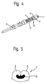
- FIG. 4 shows an error-free crimp connection in which a window 13, the insulation 11 of the conductor end 1 and the Individual strands of the conductor wire 12 are visible. At the contact-side end of the wire crimps 7 are the Individual strands visible again.
- Fig. 5 shows how a fault-free Drahtcrimp 7 the second double tabs 6 with the trained as a stranded wire Conductor wire 12 are squeezed.
- 14 is a stand without right Sidewall designated at which a motor 15 and an am Stand 14 mounted gear 16 is arranged. Moreover 14 first guides 17 are arranged on the stand, where a crimping rod 18 is guided. One from the transmission 16 driven shaft 19 has at one end an eccentric pin 20 on the other end is a resolver 21 for detecting the Angle of rotation coupled.
- the Crimpbär 18 consists of a in the first guides 17 guided slider 22 and out a tool holder 23 with force sensor 23.1 and holding fork 24.
- the slider 22 is in loose connection with the Eccentric pin 20, wherein the rotational movement of the Eccentric 20 in a linear movement of the slider 22 is implemented.
- the maximum stroke of the slider 22nd is determined by top dead center and bottom dead center of the Eccentric 20 determined.
- the tool holder 23 is actuated Usually a tool that works together with a for Tool belonging anvil 9.1 the crimp connection manufactures.
- a crimping simulator 25 is used instead of the tool.
- the stroke can be precise to be adjusted.
- an operator terminal 27 is provided as interface between operator and Crimping press.
- the operator terminal 27 has a rotary knob 29 and a Keyboard 30 on and to visualize data is one Display 31 is provided.
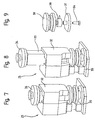
- FIGS. 7, 8 and 9 show details of the crimping simulator 25 for calibration of the force sensor 23.1.
- One in one Tool housing 32 guided punch 33 has a Carrier head 34 which in loose connection with the Holding fork 24 of the tool holder 23 is.
- On one foot 35 of the tool housing 32 is for example by means of a Screw 36 a base plate 37 attached, the one Load cell 38 carries.
- the power of the punch 33 is via an intermediate piece 39 on the force transducer 38th transfer.
- the intermediate piece 39 is elastic and has the Consequence that in the calibration of the force increase in time is stretchable.
- the force transducer 38 for example a Quartz force transducer, is expensive, calibratable and has a very linear characteristic.
- the built-in tool holder 23 Force sensor 23.1 is cheaper and has a bigger one Linearity error.
- For calibration of the force sensor 23.1 is the stamp 33 from the top dead center in the bottom dead center and back to the top dead center moves and a force in the course and in the order of magnitude a real crimping generated. It is the Force progression simultaneously and exclusively depending on Force sensor 23.1 and detected by the force transducer 38 and stored, wherein the force transducer 38 the calibratable Force history detected. This is also a force calibration at Force sensor 23.1 possible.
- the force curve and the through the nonlinearity of the force sensor 23.1 conditional Force deviations from the measured force curve of Force transducer 38 are detected and in one Correction table filed.
- Fig. 9a shows a voltage Crimpkraftverlauf the Force sensor 23.1.
- Voltage U for example in Volts
- crimp force CK for example, in kilonewtons.
- undressed Line is the nonlinear voltage curve of the Force sensor 23.1 shown.
- the broken line shows the linear voltage curve of the crimping simulator 25.
- Fig. 10 shows the force sensor 23.1, as in the Tool holder 23 is installed.
- Fig. 11 shows the Individual parts of the force sensor 23.1.
- the force sensor 23.1 consists of a sensor housing 40 with an example plastic existing bottom 41 and cover 42.
- the Inside the bottom 41 and the lid 42 are provided with a electrically conductive layer, for example one Copper layer 43, laminated.
- the layer 43 of the floor 41 is by means of a lead wire 44 to the inner conductor a connection socket 45 connected.
- the case of the Socket 45 is directly connected to the coating of the Cover 42 connected.
- the sensor housing 40 has one Plastic existing intermediate bottom 46 with lesser Thickness than the sensors 48, on the recesses 47th are arranged, the holder of the sensors 48, For example, piezo ceramic discs serve.
- the at Calibration or crimping on the lid 42 exerted force is exclusively on the sensors 48 and transferred from these to the ground 41.
- the pressure on the sensors 48 generate an electrical charge which is at the Socke
- Fig. 12 shows details of the controller 28 for the Crimping press.
- One at the entrance with a net filter 49 Equipped Converter 50 puts the mains voltage in one DC voltage at which an inverter 51 is fed.
- Controlled semiconductor switches Gu ... Gz of the inverter 51 chop up the DC voltage in one Pulse width modulation method in three pulsed AC voltages in the motor 15, for example, a Asynchronous motor ASM, sinusoidal currents of variable frequency produce.
- the rotational movement is from the engine 15 to the Transmission 16 and then transferred to the shaft 19, at the one end of the eccentric pin 20 and at the other end the resolver 21 is arranged.
- the eccentric pin 20 puts the crimping rod 18 in a linear motion.
- One Pulse generator 52 generates in function of a Soll Anlagensverlaufes that for the control of Semiconductor switch Gu ... Gz necessary pulse pattern, the a driver stage 53 is fed to the output with the control lines of the semiconductor switches Gu ... Gz connected is.
- a computer 54 controls all the functions of Crimping press. For the exchange of data between the computer and the peripheral modules is the bus system 55 to Available.
- An automatically different Network adaptive power supply 56 also generates the necessary for the operation of the controller 28 Auxiliary voltages.
- a battery-backed write-read memory 57 is used for Calculator 54 as a working memory.
- a read memory 58 the program for controlling the crimping press is stored.
- Other machines involved in the crimping process such as for example, conductor feed or contact feed, Control devices, safety circuits, etc. are with the Reference numeral 59 denotes and communicate for example, for synchronization via bus system 55 with the Control 28.
- the control terminal 27 is by means of a serial interface 60 connected to the computer 54. If the crimp press to a parent Jardinkonfedictioniertechnik 63 heard takes place the Communication of the controller 28 with the assembly unit 63 also via the serial interface 60.
- a Evaluation unit 61 detects the measured values of the force sensor 23.1 and the force transducer 38 and processes the Measurement data as shown above.
- menu-guided user-specific Data such as password, language, units, etc.
- operation-specific data such as acceleration, deceleration, Frequency of the motor, position points along the stroke to the Synchronization of the peripherals involved in the crimping process Machinery and equipment are entered.
- service-relevant data such as service-relevant data, statistical evaluations, Log data of the communication, drive data etc. be accessed.
- Operating modes such as calibration of the Starting position of the crimping rod 18, calibration of the Force sensor 23.1, Einricht religion to specify the for the respective tool necessary stroke, triggering a one-time crimping process for testing the crimped connection, Crimping with intermediate stop for positioning the Contact and subsequent pressing of the contact, Crimping with preselected stroke, etc. can also menu guided via operating terminal 27 of the controller 28 given, wherein the Crimpbär 18 and thus the Crimping tool can be positioned by means of knob 39.
- the resolver 21 used in the crimp press serves the Measurement of angular positions. He delivers an absolute Signal per revolution and is insensitive to Vibration loads and temperature. Because of his Mechanical construction also maintains its angle information received in case of power failure.
- the resolver 21 consists of a stator and a driven by the shaft 19 Rotor. At the stator is a first stator winding and a second stator winding and a rotor winding on the rotor arranged.
- the rotor winding is replaced by a Alternating voltage U1 with constant amplitude and frequency, For example, 5000 Hz excited.
- the second stator winding is shifted from the first stator winding by 90 ° arranged.
- Fig. 13 to 15 show the course of the crimping force of a typical contact family at different Crimpsciencen.
- the Crimping force is CK and on the horizontal graph axis the time, the deflection angle or the Crimpweg applied.
- the Crimpweg CW is the deflection angle ⁇ of Resolver 21 derived.
- the curve with a solid line is one out of, say, ten faultless crimps determined and the mean of these crimping forces representative reference curve. With broken line shown is the force curve of a faulty Crimping.
- Fig. 13 shows the force curve of a crimping, in the Drahtcrimp 7 three of nineteen single strands of the Conductor wire 12 is missing. The three individual strands are either pushed back when positioning the conductor been and / or cut off during stripping. In a first zone Z1 of the force curve, which is about the Closing operation of the double tabs 4, 6 reproduces lie the reference curve and the faulty crimp curve on each other, which is represented by the sign + -.
- a second zone Z2 of the force curve which is about the Pressing the first double lug 4 in the conductor insulation 11 and the pressing of the second double lug 6 in the Conductor 12 reproduces, the values of the faulty crimping well below the reference values, what is represented by the sign ---.
- a third zone Z3 of the force curve which is about the final plastic deformation of the double lugs 4, 6 reproduces, the values of the faulty crimping are still something below the reference values, what about the signs is shown.
- the area to the right of the third zone Z3 reflects the force curve during the opening process of the tool. In this area, the curves cover largely independent of the error of crimping.
- Fig. 14 shows the force curve of a crimp, in which the Conductor insulation 11 extends into the wire crimp 7.
- the Force curve of the faulty crimping a significant Elevation compared to the reference curve on what with the Sign ++++ is shown.
- the closing of the second Double lug 6 requires 11 more because of the conductor insulation Force.
- Fig. 15 shows the force curve of a crimp, in which the Lead wire 12 only partially extends into the wire crimp 7.
- the Force curve of the faulty crimping clearly below the reference curve, what with the sign - or with the Sign --- is shown.
- the deformation of the Double lugs 4, 6 in case of incomplete filling Insulation crimp 4 and wire crimp 6 requires less force.
- the crimping force CK is determined by means of a Force sensor 23.1 measured.
- the crimping force CK divides into the crimping dies 8, 9 on.
Description
Die Erfindung betrifft ein Verfahren und eine Einrichtung zur Bestimmung der Qualität einer Crimpverbindung zwischen einem Leiter und einem Kontakt, wobei die Einrichtung eine Crimpkraft erzeugt, mittels welcher der Kontakt mit dem Leiter elektrisch und mechanisch unlösbar verbindbar sind.The invention relates to a method and a device for determining the quality of a crimp connection between a conductor and a contact, the device having a Crimp force generated by means of which the contact with the Ladder electrically and mechanically insoluble connectable.
Der Begriff "Crimpen" ist international eingeführt und normungstechnisch festgelegt. In der Praxis werden aber auch Ausdrücke wie Pressen, Quetschen, Anschlagen oder Ansetzen benutzt. Unter Crimpen versteht man die Herstellung einer nicht lösbaren elektrischen und mechanischen Verbindung zwischen einem Leiter und einem Kontakt. Beim Crimpvorgang wird das zu verbindende Material plastisch, dauerhaft verformt. Dabei werden, falls vorhanden, schlecht leitende Oberflächenschichten aufgebrochen, was die elektrische Leitfähigkeiten begünstigt. Eine korrekte Crimpung verhindert aber auch das Eindringen korrosiver Medien selbst unter erschwerten Betriebsbedingungen wie Temperaturwechsel oder Vibration.The term "crimping" is internationally established and determined by standardization. In practice, however, will be also expressions like pressing, bruising, striking or Applying used. By crimping one understands the Production of a non-releasable electrical and mechanical connection between a conductor and a Contact. During crimping, the material to be joined becomes plastic, permanently deformed. In doing so, if present, poorly conductive surface layers broken up what the electrical conductivities favored. Correct crimping also prevents this Penetration of corrosive media even under difficult Operating conditions such as temperature changes or vibration.
Ziel der Crimpung ist die Herstellung einer guten mechanischen und elektrischen Verbindung, die auf die Dauer qualitativ unverändert bleibt.The aim of crimping is to produce a good one mechanical and electrical connection in the long run qualitatively unchanged.
Zum Crimpen werden kontaktspezifische Crimpwerkzeuge verwendet mit einem feststehenden Crimpamboss unten und vertikal verschiebbaren Crimpstempeln oben. (Fig. 1 bis Fig. 3). Im Crimpwerkzeug sind der Drahtcrimper und der Isolationscrimper montiert, welche meistens über Rasterscheiben mit unterschiedlichen Höhennocken unabhängig voneinander in vertikaler Richtung auf den Drahtdurchmesser bzw. Isolationsdurchmesser eingestellt werden können. Diese Einstellungen beeinflussen direkt die Qualität der Crimpverbindung.For crimping contact-specific crimping tools used with a fixed crimp anvil down and vertically displaceable crimp punches above. (FIGS. 1 to Fig. 3). In the crimping tool are the wire crimper and the Insulation crimper mounted, which mostly over Grid discs with different height cam independently from each other in the vertical direction to the wire diameter or insulation diameter can be adjusted. These Settings directly affect the quality of the Crimp.
Bei offenen Crimpkontakten (Fig. 4 und Fig. 5) erfolgt die Leiterzuführung oberhalb des Kontaktes. Der zuvor abisolierte Leiter wird üblicherweise von Automaten gleichzeitig in radialer und axialer Richtung gegenüber dem Kontakt korrekt für den Crimpvorgang positioniert. Durch die Abwärtsbewegung des Crimpstempels wird zuerst der Leiter über eine Mechanik in die nach oben geöffneten Draht- und Isolationscrimpkrallen abgesenkt, danach beginnt der eigentliche Crimpvorgang mit Umformen der Laschen entsprechend der Crimpstempelformen. Nach dem Hub des Crimpstempels hat der Crimp die gewollte Form-Verpressung. (Fig. 5), die wiederum vom verwendeten Kontaktblech, vom Drahtquerschnitt, vom Kupfer des Drahtes und von der Abisolierung abhängig ist. Bei geschlossenen Kontakten muss nach radialer Ausrichtung axial in den als Rohr ausgeformten Crimpbereich eingefahren werden.With open crimp contacts (FIGS. 4 and 5), the Conductor feed above the contact. The before stripped conductors are commonly used by vending machines simultaneously in the radial and axial direction with respect to the Contact correctly positioned for the crimping process. By the downward movement of the crimping die becomes the first Head over a mechanism in the upwards opened Wire and insulation crimping claws lowered, then begins the actual crimping process with forming the tabs according to the crimping die shapes. After the stroke of Crimp stamp, the crimp has the desired form-pressing. (Fig. 5), in turn, from the contact plate used, from Wire cross section, from the copper of the wire and the Stripping is dependent. For closed contacts must after radial alignment axially into the tube retracted molded crimping.
Ein Schnittbild einer fehlerfrei ausgeführten Crimpverbindung zeigt die ursprünglich einzelnen runden Litzendrähte des Leiters kompakt zu Vielecken gegeneinander gepresst. Die innere Fläche im Crimpbereich des Kontaktes zeigt Verformungen der Berührungsstellen der Einzellitzen. Beim Drahtcrimp müssen alle Einzeldrähte umfasst sein. Am vorderen Ende des Drahtcrimps müssen die Einzeldrähte je nach Querschnitt etwa 0,5 mm herausragen und dürfen nicht im Crimp verschwinden. In dem zwischen Drahtcrimp und Isolationscrimp liegenden Fenster müssen Leiter und Leiterisolation sichtbar sein. Der Isolationscrimp muss die Isolation umschliessen ohne in diese einzudringen. A sectional view of a faultless running Crimp connection shows the original single round Litz wires of the conductor compact to polygons against each other pressed. The inner surface in the crimp area of the contact shows deformations of the contact points of the individual strands. When wire crimping all individual wires must be included. At the the front end of the wire crimps must have the individual wires each protrude after cross section about 0.5 mm and may not disappear in the crimp. In between wire crimp and Isolation crimp lying windows must be ladder and Conductor insulation visible. The insulation crimp must be the Enclose isolation without entering it.
Wichtige Kriterien für die Beurteilung einer Crimpverbindung sind die Crimpform, die Crimphöhe und die Drahtausreiss-Festigkeit. Diese Art Kriterien eignen sich aber nur beim Einrichten der Crimpmaschine und während der Produktion bei Stichproben. Um den heutigen Qualitätsanforderungen für sämtliche Crimpverbindungen zu genügen, müssen Mittel zur Verfügung sein, welche über jede Crimpverbindung während des Crimpvorganges Crimpdaten aufnehmen, auswerten, speichern und ergebnisorientiert Maschinendaten beeinflussen können. Zur Beurteilung der Crimpverbindung (ohne mechanische Zerstörung der Crimpverbindung) wird die Crimpkraft in Relation zum Crimpweg oder zur Crimpzeit gesetzt. Mit entsprechender Auswertung der Crimpdaten kann die Güte einer Crimpverbindung verlässlich beurteilt werden.Important criteria for the evaluation of a Crimp connection are the crimp shape, the crimp height and the Drahtausreiss strength. These types of criteria are suitable but only when setting up the crimping machine and during the Production by sampling. To the today Quality requirements for all crimp connections too Sufficient means must be available, which over each Crimp connection during crimping Crimp data record, evaluate, save and result-oriented Machine data. To judge the Crimp connection (without mechanical destruction of the Crimped) is the crimp force in relation to Crimping path or set at crimping time. With appropriate Evaluation of the crimp data can be the goodness of a Crimp connection can be reliably assessed.
Eine Verfahren bzw. eine Einrichtung zur Beurteilung der Qualität einer Crimpverbindung muss Crimpfehler wie falsche Isolationscrimp-Höhe, falsche Drahtcrimp-Höhe, nicht erfasste Litzendrähte beim Drahtcrimp, falsche oder keine Abisolierlänge, falsche Einlegetiefe oder beim Abisolieren abgeschnittene Litzendrähte erkennen und entsprechende Fehlermeldungen erzeugen.A method and a device for assessing the Quality of a crimped connection must be crimped as wrong Insulation crimp height, wrong wire crimp height, not detected strand wires at wire crimp, wrong or none Stripping length, incorrect insertion depth or stripping Detect cut stranded wires and corresponding Generate error messages.
Aus der Anmeldeschrift EP 0 460 441 ist ein Verfahren zur
Detektion von fehlenden Litzen oder von eingecrimpter
Leiterisolation in einer Crimpverbindung anhand des
Crimpkraftverlaufes bekannt geworden. Während eines
Crimpvorganges werden Wertepaare bestehend aus Crimpkraft
und Position des Crimpstempels gemessen und gespeichert.
Die während der Herstellung einer Crimpverbindung
gemessenen Wertepaare ergeben den Crimpkraftverlauf des
Crimpvorganges mit der Crimpkraft in Abhängigkeit der
Position des Crimpstempels. Der Kurvenabschnitt mit starkem
Kraftanstieg wird linearisiert und ein Punkt aus dem Mittel
der minimalen und maximalen Crimpkraft bestimmt. Der Punkt
wird mit einem Referenzwert verglichen. Falls der Punkt
innerhalb einer vorbestimmten Abweichung vom Referenzwert
liegt, ist die Crimpverbindung von akzeptabler Qualität.
Bei der Auswertung des Crimpkraftverlaufes des
Crimpvorganges wird auch die maximale Crimpkraft
mitberücksichtigt. Falls die maximale Crimpkraft gegenüber
einem Referenzwert übermässig abweicht, wird die
Crimpverbindung als unbrauchbar zurückgewiesen. Der Punkt
im Kurvenabschnitt mit starkem Kraftanstieg und die
maximale Crimpkraft geben Aufschluss über fehlende Litzen
bzw. über eingecrimpte Leiterisolation in der
Crimpverbindung.The
Bei einer marktgängigen Crimppresse erfasst ein Kraftsensor während des Crimpvorganges die Kraft, die in digitaler Form als kraftabhängiger Kurvenverlauf abgespeichert wird. Dieser wird mit einer Referenzkurve verglichen. Je nach Grösse der Abweichung zur Referenz wird auf den Typ des Crimpfehlers geschlossen.In a marketable crimping press detects a force sensor during the crimping process the force, in digital form is stored as a force-dependent curve. This is compared with a reference curve. Depending on Size of the deviation from the reference is based on the type of Crimpfehlers closed.
Nachteilig bei dieser Einrichtung bzw. bei diesem Verfahren ist, dass trotz grossem Rechner-, Speicher- und Rechenaufwand keine differenzierte Aussage über die Qualität der Crimpverbindung möglich ist.A disadvantage of this device or in this method is that despite large computer, memory and Computational effort no differentiated statement about the Quality of the crimp connection is possible.
Hier will die Erfindung Abhilfe schaffen. Die Erfindung,
wie sie in Anspruch 1 gekennzeichnet ist, löst die Aufgabe,
die Nachteile der bekannten Einrichtung zu vermeiden und
ein Verfahren und eine Einrichtung mit verbesserter
Fehlersensibilität zu schaffen.The invention aims to remedy this situation. The invention,
as characterized in
Die durch die Erfindung erreichten Vorteile sind im wesentlichen darin zu sehen, dass mit der besseren Auflösung der Fehler eine Qualitätssteigerung möglich ist, dass mit der sensibleren Fehlerdiagnose weniger Ausschuss entsteht und dass Folgefehler, beispielsweise eine Panne eines Personenwagens wegen Wackelkontaktes in einer Steckerverbindung vermieden werden.The advantages achieved by the invention are in essential to see that with the better Resolution of the error an increase in quality is possible that with the more sensitive fault diagnosis less waste arises and that consequential errors, such as a breakdown a passenger car because of loose contact in one Plug connection can be avoided.
Im folgenden wird die Erfindung anhand von lediglich einen Ausführungsweg darstellenden Zeichnungen näher erläutert. Es zeigen:
- Fig. 1 bis Fig. 3
- eine schematische Darstellung eines Crimpvorganges,
- Fig. 4
- eine Crimpverbindung zwischen einem Leiter und einem Kontakt,
- Fig. 5
- Einzelheiten eines Drahtcrimps,
- Fig. 6
- eine Crimppresse mit einem Crimpsimulator zur Kalibrierung eines Kraftsensors,
- Fig. 7
- den Crimpsimulator mit einem Stempel in der unteren Totpunktlage,
- Fig. 8
- den Crimpsimulator mit dem Stempel in der oberen Totpunktlage,
- Fig. 9
- Einzelheiten des Crimpsimulators,
- Fig. 9a
- einen Spannungs-Crimpkraftverlauf des Kraftsensors,
- Fig. 10 und Fig. 11
- Einzelheiten des Kraftsensors,
- Fig. 12
- Einzelheiten einer Pressensteuerung,
- Fig. 13 bis Fig. 15
- den Verlauf der Crimpkraft bei unterschiedlichen Crimpfehlern,
- Fig. 16
- den Crimpkraftverlauf mit einer Zoneneinteilung,
- Fig. 17
- Zonenabhängige Mess- und Rechenwerte und
- Fig. 18a bis Fig. 18c
- Grenzwerte für Fehlertypen.
- Fig. 1 to Fig. 3
- a schematic representation of a crimping process,
- Fig. 4
- a crimp connection between a conductor and a contact,
- Fig. 5
- Details of a wire crimp,
- Fig. 6
- a crimping press with a crimping simulator for calibrating a force sensor,
- Fig. 7
- the crimp simulator with a punch in the bottom dead center,
- Fig. 8
- the crimp simulator with the punch in the top dead center position,
- Fig. 9
- Details of the crimp simulator,
- Fig. 9a
- a voltage crimp force curve of the force sensor,
- 10 and FIG. 11
- Details of the force sensor,
- Fig. 12
- Details of a press control,
- FIGS. 13 to 15
- the course of the crimping force at different crimping errors,
- Fig. 16
- the Crimpkraftverlauf with a zoning,
- Fig. 17
- Zone-dependent measurement and calculation values and
- Fig. 18a to Fig. 18c
- Limits for error types.
Fig. 1 bis 3 zeigen einen Crimpvorgang, bei dem das Ende
eines Leiters 1 mit einem Kontakt 2 verbunden wird. Eine
offene Crimpzone 3 des Kontaktes 2 weist eine erste
Doppellasche 4 für den Isolationscrimp 5 und eine zweite
Doppellasche 6 für einen Drahtcrimp 7 auf. Fig. 1 zeigt
Crimpstempel 8, 9 in der oberen Totpunktlage, das Ende der
Leiterisolation liegt in der ersten Doppellasche 4 und das
abisolierte Leiterstück liegt in der zweiten Doppellasche
6. Wie in Fig. 2 gezeigt werden beim Absenken der
Crimpstempel 8, 9 die Doppellaschen 4, 6 mittels
keilförmigen Ausnehmungen 10 der Crimpstempel 8, 9
gegeneinander gepresst. Als Auflage dient ein Ambos 9.1.
Ein kuppelförmiges oberes Ende der Ausnehmung 10 gibt der
Doppellasche 4, 6 zusammen mit der Leiterisolation bzw. dem
Leiterdraht die endgültige Form. Fig. 3 zeigt die fertige
Crimpverbindung mit dem Isolationscrimp 5, bei dem die
erste Doppellasche 4 um die Leiterisolation 11 gepresst ist
und mit dem Drahtcrimp 7, bei dem die zweite Doppellasche 6
um einen Leiterdraht 12 gepresst ist.Figs. 1 to 3 show a crimping process in which the end
a
Fig. 4 zeigt eine fehlerfreie Crimpverbindung, bei der in
einem Fenster 13 die Isolation 11 des Leiterendes 1 und die
Einzellitzen des Leiterdrahtes 12 sichtbar sind. Am
kontaktseitigen Ende des Drahtcrimps 7 sind die
Einzellitzen erneut sichtbar.FIG. 4 shows an error-free crimp connection in which
a
Fig. 5 zeigt wie bei einem fehlerfreien Drahtcrimp 7 die
zweiten Doppellaschen 6 mit dem als Litze ausgebildeten
Leiterdraht 12 verquetscht sind.Fig. 5 shows how a fault-
In den Fig. 6 bis 12 ist mit 14 ein Ständer ohne rechte
Seitenwand bezeichnet, an dem ein Motor 15 und ein am
Ständer 14 gelagertes Getriebe 16 angeordnet ist. Ausserdem
sind am Ständer 14 erste Führungen 17 angeordnet, an denen
ein Crimpbär 18 geführt ist. Eine vom Getriebe 16
angetriebene Welle 19 weist einenends einen Exzenterzapfen
20 auf, anderenends ist ein Resolver 21 zur Erfassung des
Drehwinkels angekoppelt. Der Crimpbär 18 besteht aus einem
in den ersten Führungen 17 geführtes Gleitstück 22 und aus
einem Werkzeughalter 23 mit Kraftsensor 23.1 und Haltegabel
24. Das Gleitstück 22 steht in loser Verbindung mit dem
Exzenterzapfen 20, wobei die Rotationsbewegung des
Exzenterzapfens 20 in eine Linearbewegung des Gleitstückes
22 umgesetzt wird. Der maximale Hub des Gleitstückes 22
wird durch den oberen Totpunkt und den unteren Totpunkt des
Exzenterzapfens 20 bestimmt. Der Werkzeughalter 23 betätigt
üblicherweise ein Werkzeug, das zusammen mit einem zum
Werkzeug gehörenden Amboss 9.1 die Crimpverbindung
herstellt. Zur Kalibrierung des Kraftsensors 23.1 ist
anstelle des Werkzeugs ein Crimpsimulator 25 eingesetzt.
Mittels einer Justierschraube 26 kann der Hub präzise
justiert werden. Als Schnittstelle zwischen Bediener und
Crimppresse ist ein Bedienterminal 27 vorgesehen. Zur
Eingabe von Betriebsdaten und Befehlen an eine Steuerung 28
weist das Bedienterminal 27 einen Drehknopf 29 und eine
Tastatur 30 auf und zur Visualisierung von Daten ist eine
Anzeige 31 vorgesehen. In FIGS. 6 to 12, 14 is a stand without right
Sidewall designated at which a
Fig. 7, 8 und 9 zeigen Einzelheiten des Crimpsimulators 25
zur Kalibrierung des Kraftsensors 23.1. Ein in einem
Werkzeuggehäuse 32 geführter Stempel 33 weist einen
Trägerkopf 34 auf, der in loser Verbindung mit der
Haltegabel 24 des Werkzeughalters 23 steht. An einem Fuss
35 des Werkzeuggehäuses 32 ist beispielsweise mittels einer
Schraube 36 eine Grundplatte 37 befestigt, die einen
Kraftaufnehmer 38 trägt. Die Kraft des Stempels 33 wird
über ein Zwischenstück 39 auf den Kraftaufnehmer 38
übertragen. Das Zwischenstück 39 ist elastisch und hat zur
Folge, dass bei der Kalibrierung der Kraftanstieg zeitlich
dehnbar ist. Der Kraftaufnehmer 38, beispielsweise ein
Quarz-Kraftaufnehmer, ist teuer, eichbar und hat eine sehr
lineare Kennlinie. Der im Werkzeughalter 23 eingebaute
Kraftsensor 23.1 ist billiger und hat einen grösseren
Linearitätsfehler. Zur Kalibrierung des Kraftsensors 23.1
wird der Stempel 33 von der oberen Totpunktlage in die
untere Totpunktlage und wieder in die obere Totpunktlage
bewegt und eine Kraft im Verlauf und in der Grössenordnung
eines echten Crimpvorganges erzeugt. Dabei wird der
Kraftverlauf gleichzeitig und ausschliesslich je vom
Kraftsensor 23.1 und vom Kraftaufnehmer 38 erfasst und
gespeichert, wobei der Kraftaufnehmer 38 den eichbaren
Kraftverlauf erfasst. Damit ist auch eine Krafteichung beim
Kraftsensor 23.1 möglich. Der Kraftverlauf und die durch
die Nichtlinearität des Kraftsensors 23.1 bedingten
Kraftabweichungen gegenüber dem gemessenen Kraftverlauf des
Kraftaufnehmers 38 werden erfasst und in einer
Korrekturtabelle abgelegt. Nach dem Kalibriervorgang wird
der Crimpsimulator 25 ausgebaut und das übliche
Crimpwerkzeug eingesetzt. Falls der Kraftsensor 23.1
ersetzt wird, muss der Kalibriervorgang wiederholt werden.
Zur Messung der Crimpkraft bei der Herstellung von
Crimpverbindungen genügt der Kraftsensor 23.1, weil der
Kraftsensor 23.1 geeicht ist und die durch die
Nichtlinearität des Kraftsensors 23.1 bedingten
Messabweichungen mittels der Korrekturtabelle korrigiert
werden. Auf diese Weise kann mit einem billigen, an sich
ungenauen Kraftsensor der Crimpkraftverlauf genau und
absolut bestimmt werden. Weiter vorteilhaft ist, dass ein
Hersteller von Crimpverbindungen für seinen üblicherweise
aus mehreren gleichen Crimppressen bestehenden
Maschinenpark nur einen teuren Crimpsimulator für die
Kalibrierung sämtlicher Crimppressen braucht.FIGS. 7, 8 and 9 show details of the crimping
Fig. 9a zeigt einen Spannungs-Crimpkraftverlauf des
Kraftsensors 23.1. Auf der vertikalen Diagrammachse ist die
Spannung U, beispielsweise in Volts und auf der
horizontalen Diagrammachse ist die Crimpkraft CK,
beispielsweise in Kilonewton aufgetragen. Mit ausgezogener
Linie ist der nichtlineare Spannungsverlauf des
Kraftsensors 23.1 dargestellt. Die unterbrochene Linie
zeigt den linearen Spannungsverlauf des Crimpsimulators 25.
In einem Kalibriervorgang werden bei beispielsweise hundert
Kraftwerten die jeweils zugehörigen Spannungsdifferenzen
zwischen ausgezogener Linie und unterbrochener Linie
festgehalten und in der oben genannten Korrekturtabelle als
Kraft/Spannungs-Wertepaar abgelegt. Bei der Herstellung von
Crimpverbindungen werden die entsprechenden Kraftwerte aus
der Korrekturtabelle gelesen und die jeweils zugehörigen
Spannungsdifferenzen zu den entsprechenden aktuell
gemessenen Spannungen addiert.Fig. 9a shows a voltage Crimpkraftverlauf the
Force sensor 23.1. On the vertical graph axis is the
Voltage U, for example in Volts and on the
horizontal diagram axis is the crimp force CK,
for example, in kilonewtons. With undressed
Line is the nonlinear voltage curve of the
Force sensor 23.1 shown. The broken line
shows the linear voltage curve of the crimping
Fig. 10 zeigt den Kraftsensor 23.1, wie er im
Werkzeughalter 23 eingebaut ist. Fig. 11 zeigt die
Einzelteile des Kraftsensors 23.1. Der Kraftsensor 23.1
besteht aus einem Sensorgehäuse 40 mit einem beispielsweise
aus Kunststoff bestehendem Boden 41 und Deckel 42. Die
Innenseite des Bodens 41 und des Deckels 42 sind mit einer
elektrisch leitenden Schicht, beispielsweise einer
Kupferschicht 43, kaschiert. Die Schicht 43 des Bodens 41
ist mittels eines Anschlussdrahtes 44 mit dem Innenleiter
einer Anschlussbuchse 45 verbunden. Das Gehäuse der
Anschlussbuchse 45 ist direkt mit der Beschichtung des
Deckels 42 verbunden. Das Sensorgehäuse 40 weist einen aus
Kunststoff bestehenden Zwischenboden 46 mit geringerer
Dicke als die Sensoren 48 auf, an dem Ausnehmungen 47
angeordnet sind, die der Halterung der Sensoren 48,
beispielsweise Piezo-Keramikscheiben, dienen. Die beim
Kalibriervorgang oder beim Crimpvorgang auf den Deckel 42
ausgeübte Kraft wird ausschliesslich auf die Sensoren 48
und von diesen auf den Boden 41 übertragen. Der Druck auf
die Sensoren 48 erzeugt eine elektrische Ladung, die an der
Anschlussbuchse 45 messbar ist.Fig. 10 shows the force sensor 23.1, as in the
Fig. 12 zeigt Einzelheiten der Steuerung 28 für die
Crimppresse. Ein am Eingang mit einem Netzfilter 49
ausgerüsteter Converter 50 setzt die Netzspannung in eine
Gleichspannung um, mit der ein Inverter 51 gespeist wird.
Gesteuerte Halbleiterschalter Gu ... Gz des Inverters 51
zerhacken die Gleichspannung in einem
Pulsbreitenmodulationsverfahren in drei gepulste
Wechselspannungen, die im Motor 15, beispielsweise ein
Asynchronmotor ASM, sinusförmige Ströme variabler Frequenz
erzeugen. Die Rotationsbewegung wird vom Motor 15 auf das
Getriebe 16 und dann auf die Welle 19 übertragen, an deren
einen Ende der Exzenterzapfen 20 und an deren anderen Ende
der Resolver 21 angeordnet ist. Der Exzenterzapfen 20
versetzt den Crimpbär 18 in eine Linearbewegung. Ein
Pulsgenerator 52 erzeugt in Funktion eines
Sollgeschwindigkeitsverlaufes das für die Ansteuerung der
Halbleiterschalter Gu ... Gz notwendige Pulsmuster, das
einer Treiberstufe 53 eingespeist wird, die am Ausgang mit
den Steuerleitungen der Halbleiterschalter Gu ... Gz
verbunden ist. Ein Rechner 54 steuert alle Funktionen der
Crimppresse. Für den Datenaustausch zwischen dem Rechner
und den Peripheriebausteinen steht das Bussystem 55 zur
Verfügung. Ein sich automatisch an unterschiedliche
Netzsituationen anpassendes Netzgerät 56 erzeugt auch die
für den Betrieb der Steuerung 28 notwendigen
Hilfsspannungen. Fig. 12 shows details of the
Ein batteriegestützter Schreib- Lesespeicher 57 dient dem
Rechner 54 als Arbeitsspeicher. In einem Lesespeicher 58
ist das Programm zur Steuerung der Crimppresse abgelegt.
Andere am Crimpvorgang beteiligte Maschinen, wie
beispielsweise Leiterzuführung oder Kontaktzuführung,
Steuereinrichtungen, Sicherheitskreise usw. sind mit dem
Bezugszeichen 59 bezeichnet und kommunizieren
beispielsweise zur Synchronisation via Bussystem 55 mit der
Steuerung 28. Das Bedienterminal 27 ist mittels einer
seriellen Schnittstelle 60 mit dem Rechner 54 verbunden.
Falls die Crimppresse zu einer übergeordneten
Kabelkonfektioniereinheit 63 gehört, erfolgt die
Kommunikation der Steuerung 28 mit der Konfektioniereinheit
63 auch über die serielle Schnittstelle 60. Eine
Auswerteeinheit 61 erfasst die Messwerte des Kraftsensors
23.1 und des Kraftaufnehmers 38 und verarbeitet die
Messdaten wie oben dargestellt.A battery-backed write-
Am Bedienterminal 27 können menugeführt anwenderspezifische
Daten wie Passwort, Sprache, Einheiten usw.,
betriebsspezifische Daten wie Beschleunigung, Verzögerung,
Frequenz des Motors, Positionspunkte entlang des Hubes zur
Synchronisation der am Crimpvorgang beteiligten peripheren
Maschinen und Einrichtungen eingegeben werden. Ausserdem
kann via Bedienterminal 27 auf Systeminformationen,
servicerelevante Daten, statistische Auswertungen,
Protokolldaten der Kommunikation, Antriebsdaten usw.
zugegriffen werden. Betriebsarten wie Kalibrierung der
Ausgangsposition des Crimpbärs 18, Kalibrierung des
Kraftsensors 23.1, Einrichtbetrieb zur Vorgabe des für das
jeweilige Werkzeug notwendigen Hubes, Auslösung eines
einmaligen Crimpvorganges zur Prüfung der Crimpverbindung,
Crimpvorgang mit Zwischenhalt zur Positionierung des
Kontaktes und anschliessendem Verpressen des Kontaktes,
Crimpvorgang mit vorgewähltem Hub usw. können auch
menugeführt via Bedienterminal 27 der Steuerung 28
vorgegeben, wobei der Crimpbär 18 und somit das
Crimpwerkzeug mittels Drehknopf 39 positionierbar ist.At the operating
Der in der Crimppresse eingesetzte Resolver 21 dient der
Messung von Winkelpositionen. Er liefert ein absolutes
Signal pro Umdrehung und ist unempfindlich gegenüber
Vibrationsbelastungen und Temperatur. Aufgrund seines
mechanischen Aufbaus bleibt seine Winkelinformation auch
bei Spannungsausfall erhalten. Der Resolver 21 besteht aus
einem Stator und einem von der Welle 19 angetriebenen
Rotor. Am Stator ist eine erste Statorwicklung und eine
zweite Statorwicklung sowie am Rotor eine Rotorwicklung
angeordnet. Die Rotorwicklung wird durch eine
Wechselspannung U1 mit konstanter Amplitude und Frequenz,
beispielsweise 5000 Hz erregt. Die zweite Statorwicklung
ist gegenüber der ersten Statorwicklung um 90° verschoben
angeordnet. Durch elektromagnetische Kopplung erzeugt die
Wechselspannung U1 an den Klemmen der Statorwicklungen die
beiden Spannungen Usin bzw. Ucos. Diese beiden Spannungen
haben die gleiche Frequenz wie U1. Die Amplitude ist aber
proportional zum Sinus bzw. Cosinus des mechanischen
Auslenkwinkels . Die Speisung der Rotorwicklung erfolgt
über einen Oszillator. Bei einem Resolver mit einem Polpaar
durchläuft die Amplitude der beiden Spannungen Usin und
Ucos jeweils eine Sinusschwingung pro mechanische
Umdrehung. Eine Resolverschnittstelle 62 wertet das
Sinussignal und das Cosinussignal des Resolvers 21 mit
beispielsweise einer Auflösung von 0,35° aus und
konvertiert den Winkel in einen digitalen Wert.The
Fig. 13 bis 15 zeigen den Verlauf der Crimpkraft einer
typischen Kontaktfamilie bei unterschiedlichen
Crimpfehlern. Auf der vertikalen Diagrammachse ist die
Crimpkraft CK und auf der horizontalen Diagrammachse ist
die Zeit, der Auslenkwinkel oder der Crimpweg aufgetragen.
Der Crimpweg CW ist vom Auslenkwinkel des
Resolvers 21 abgeleitet. Die Kurve mit ausgezogener Linie
ist eine aus beispielsweise zehn fehlerfreien Crimpungen
ermittelte und den Mittelwert dieser Crimpkräfte
darstellende Referenzkurve. Mit unterbrochener Linie
dargestellt ist der Kraftverlauf einer fehlerhaften
Crimpung.Fig. 13 to 15 show the course of the crimping force of a
typical contact family at different
Crimpfehlern. On the vertical graph axis is the
Crimping force is CK and on the horizontal graph axis
the time, the deflection angle or the Crimpweg applied.
The Crimpweg CW is the deflection angle of
Fig. 13 zeigt den Kraftverlauf einer Crimpung, bei der im
Drahtcrimp 7 drei von neunzehn Einzellitzen des
Leiterdrahtes 12 fehlen. Die drei Einzellitzen sind
entweder beim Positionieren des Leiters zurückgeschoben
worden und/oder beim Abisolieren abgeschnitten worden. In
einer ersten Zone Z1 des Kraftverlaufs, die etwa den
Schliessvorgang der Doppellaschen 4, 6 wiedergibt, liegen
die Referenzkurve und die Kurve der fehlerhaften Crimpung
aufeinander, was mit den Vorzeichen +- dargestellt ist. In
einer zweiten Zone Z2 des Kraftverlaufs, die etwa das
Einpressen der ersten Doppellasche 4 in die Leiterisolation
11 und das Einpressen der zweiten Doppellasche 6 in den
Leiterdraht 12 wiedergibt, liegen die Werte der
fehlerhaften Crimpung deutlich unterhalb der Referenzwerte,
was mit den Vorzeichen --- dargestellt ist. In einer
dritten Zone Z3 des Kraftverlaufs, die etwa das endgültige
plastische Verformen der Doppellaschen 4, 6 wiedergibt,
liegen die Werte der fehlerhaften Crimpung immer noch etwas
unterhalb der Referenzwerte, was mit den Vorzeichen
dargestellt ist. Der Bereich rechts der dritten Zone Z3
wiedergibt den Kraftverlauf während des Öffnungsvorganges
des Werkzeuges. In diesem Bereich decken sich die Kurven
weitgehend unabhängig vom Fehler der Crimpung.Fig. 13 shows the force curve of a crimping, in the
Fig. 14 zeigt den Kraftverlauf einer Crimpung, bei der die
Leiterisolation 11 bis in den Drahtcrimp 7 reicht. In der
ersten Zone Z1 und zu Beginn der zweiten Zone Z2 weist der
Kraftverlauf der fehlerhaften Crimpung eine deutliche
Überhöhung gegenüber der Referenzkurve auf, was mit den
Vorzeichen ++++ dargestellt ist. Das Schliessen der zweiten
Doppellasche 6 erfordert wegen der Leiterisolation 11 mehr
Kraft.Fig. 14 shows the force curve of a crimp, in which the
Conductor insulation 11 extends into the
Fig. 15 zeigt den Kraftverlauf einer Crimpung, bei der der
Leiterdraht 12 nur teilweise in den Drahtcrimp 7 reicht. In
der zweiten Zone Z2 und in der dritten Zone Z3 liegt der
Kraftverlauf der fehlerhaften Crimpung deutlich unterhalb
der Referenzkurve, was mit den Vorzeichen -- bzw. mit dem
Vorzeichen --- dargestellt ist. Die Verformung der
Doppellaschen 4, 6 bei unvollständig gefülltem
Isolationscrimp 4 und Drahtcrimp 6 benötigt weniger Kraft. Fig. 15 shows the force curve of a crimp, in which the
Wie oben erwähnt wird die Crimpkraft CK mittels eines Kraftsensors 23.1 gemessen. Die Crimpkraft CK teilt sich in den Crimpstempeln 8, 9 auf.As mentioned above, the crimping force CK is determined by means of a Force sensor 23.1 measured. The crimping force CK divides into the crimping dies 8, 9 on.
Claims (6)
- Crimping equipment for producing a crimping force, by means of which a contact is electrically and mechanically non-detachably connectible with a conductor, consisting of a drive (15, 16, 18, 19, 20) for a crimping tool, which is arranged at a tool holder (23), with at least one crimping die, a control (28), a transmitter (21) for determining a crimping travel (CW) and a force sensor (23.1) for determining the crimping force (CK), characterised in that the force sensor (23.1) can be loaded with the entire crimping force (CK), which is generated by the drive (15, 16, 18, 19, 20) in vertical direction, and is arranged above the crimping die.
- Crimping equipment according to claim 1, characterised in that the force sensor (23.1) for determination of the crimping force (CK) has in vertical direction more than one sensor element (48), which sensor elements together produce an evaluatable signal.
- Crimping equipment according to claim 2, characterised in that the sensor element (48) is a piezo element arranged between a base (41) and a cover (42) of the housing (40), wherein the inner side of the base (41) and of the cover (42) has an electrically conductive coating (43).
- Crimping equipment according to one of the preceding claims, characterised in that a crimping simulator (25) is provided, instead of the crimping tool, for precise detection of the crimping force (CK) during a calibrating process serving for calibration of the force sensor (23.1).
- Crimping equipment according to claim 4, characterised in that the control (28) comprises a correction table in which the force deviations, which are caused by the nonlinearity of the force sensor (23.1), compared with the force path measured by means of the crimping simulator (25) are filed and that the force sensor (23.1) can be calibrated to a force path by means of the crimping simulator (23).
- Crimping equipment according to claim 5, characterised in that the control (28) comprises a correction device which during the crimping process linearises the crimping force path, which is measured by means of the force sensor (23.1), by way of the correction table.
Priority Applications (1)
| Application Number | Priority Date | Filing Date | Title |
|---|---|---|---|
| EP02002743A EP1211761B1 (en) | 1997-09-11 | 1998-09-01 | Method and apparatus for determinating the quality of a crimped connection |
Applications Claiming Priority (4)
| Application Number | Priority Date | Filing Date | Title |
|---|---|---|---|
| EP97810648 | 1997-09-11 | ||
| EP97810648 | 1997-09-11 | ||
| EP19980116524 EP0902509B1 (en) | 1997-09-11 | 1998-09-01 | Method for determinating the quality of a crimped connection |
| EP02002743A EP1211761B1 (en) | 1997-09-11 | 1998-09-01 | Method and apparatus for determinating the quality of a crimped connection |
Related Parent Applications (1)
| Application Number | Title | Priority Date | Filing Date |
|---|---|---|---|
| EP19980116524 Division EP0902509B1 (en) | 1997-09-11 | 1998-09-01 | Method for determinating the quality of a crimped connection |
Publications (2)
| Publication Number | Publication Date |
|---|---|
| EP1211761A1 EP1211761A1 (en) | 2002-06-05 |
| EP1211761B1 true EP1211761B1 (en) | 2005-12-14 |
Family
ID=26148061
Family Applications (2)
| Application Number | Title | Priority Date | Filing Date |
|---|---|---|---|
| EP19980116524 Expired - Lifetime EP0902509B1 (en) | 1997-09-11 | 1998-09-01 | Method for determinating the quality of a crimped connection |
| EP02002743A Expired - Lifetime EP1211761B1 (en) | 1997-09-11 | 1998-09-01 | Method and apparatus for determinating the quality of a crimped connection |
Family Applications Before (1)
| Application Number | Title | Priority Date | Filing Date |
|---|---|---|---|
| EP19980116524 Expired - Lifetime EP0902509B1 (en) | 1997-09-11 | 1998-09-01 | Method for determinating the quality of a crimped connection |
Country Status (1)
| Country | Link |
|---|---|
| EP (2) | EP0902509B1 (en) |
Families Citing this family (17)
| Publication number | Priority date | Publication date | Assignee | Title |
|---|---|---|---|---|
| US7024752B2 (en) | 2002-07-10 | 2006-04-11 | Komax Holding Ag | Crimping press with contact feed |
| EP1381123B1 (en) * | 2002-07-10 | 2011-06-22 | Komax Holding AG | Crimping press having a feeding device |
| EP1515403B1 (en) * | 2003-09-10 | 2007-10-24 | komax Holding AG | Cable processing apparatus |
| DE102004043776B3 (en) * | 2004-09-10 | 2006-06-14 | Bernhard Schäfer Werkzeug- und Sondermaschinenbau GmbH | Motor-driven crimping device |
| DE102008030773B4 (en) * | 2008-06-28 | 2013-12-24 | GFE - Gesellschaft für Fertigungstechnik und Entwicklung Schmalkalden e.V. | Arrangement for integrating measuring electronics in crimping tools |
| US8746026B2 (en) | 2008-10-02 | 2014-06-10 | Komax Holding Ag | Method for determining the quality of a crimped connection between a conductor and a contact |
| US9331447B2 (en) | 2010-12-07 | 2016-05-03 | Tyco Electronics Corporation | Crimping apparatus having a crimp quality monitoring system |
| TWI608677B (en) | 2012-08-15 | 2017-12-11 | 威查格工具廠有限公司 | Exchanging adapter for a crimp machine |
| DE102013211045A1 (en) * | 2013-06-13 | 2014-12-18 | Otto Bihler Handels-Beteiligungs-Gmbh | Forming method with control of a geometric property of a workpiece and device thereto |
| DE102014018995A1 (en) | 2014-12-18 | 2016-06-23 | GM Global Technology Operations LLC (n. d. Gesetzen des Staates Delaware) | Method for operating a headlight and motor vehicle headlights |
| DE102015010042A1 (en) | 2015-08-01 | 2017-02-02 | GM Global Technology Operations LLC (n. d. Ges. d. Staates Delaware) | Test arrangement for testing at least one connection interface and method for testing at least one connection interface with a test arrangement |
| DE102017213147A1 (en) * | 2017-07-31 | 2019-01-31 | Bayerische Motoren Werke Aktiengesellschaft | Method for checking connectors |
| CN109655242A (en) * | 2017-10-10 | 2019-04-19 | 中国商用飞机有限责任公司 | For detecting the method and apparatus for the reliability that harness is connect with termination case |
| DE102019101017A1 (en) * | 2019-01-16 | 2020-07-16 | Harting Electric Gmbh & Co. Kg | Method and device for monitoring the status of a crimping device |
| DE102019101016A1 (en) * | 2019-01-16 | 2020-07-16 | Harting Electric Gmbh & Co. Kg | Method and device for checking the quality of a crimp |
| CH716048B1 (en) * | 2019-04-09 | 2024-02-15 | Dietmar Kramer Dr Sc Techn Eth Phd | Method and a measuring device for measuring utensils for presses. |
| DE102020111790A1 (en) | 2020-04-30 | 2021-11-04 | Bayerische Motoren Werke Aktiengesellschaft | Method for the non-destructive testing of a hose connection |
Family Cites Families (5)
| Publication number | Priority date | Publication date | Assignee | Title |
|---|---|---|---|---|
| DE2906407C2 (en) * | 1979-02-20 | 1981-02-26 | Kistler Instrumente Ag, Winterthur (Schweiz) | Piezoelectric transducer element for installation in pressure, force or acceleration sensors |
| US4914602A (en) * | 1987-05-13 | 1990-04-03 | Furukawa Electric Co., Ltd. | Method for detecting the molding defectiveness of a press-molded workpiece and a terminal press-bonding apparatus utilizing the same |
| DE4014221A1 (en) * | 1989-05-12 | 1990-11-15 | Siemens Ag | Production monitoring of crimped electrical connectors - using built in strain gauge to measure load as indication of crimping quality |
| GB8927466D0 (en) * | 1989-12-05 | 1990-02-07 | Amp Gmbh | Electrical terminal crimping apparatus |
| DE4337797B4 (en) * | 1993-11-05 | 2007-05-31 | Kmf Messtechnik Und Verwaltungs Gmbh | Arrangement for detecting the force between relatively moving machine parts |
-
1998
- 1998-09-01 EP EP19980116524 patent/EP0902509B1/en not_active Expired - Lifetime
- 1998-09-01 EP EP02002743A patent/EP1211761B1/en not_active Expired - Lifetime
Also Published As
| Publication number | Publication date |
|---|---|
| EP1211761A1 (en) | 2002-06-05 |
| EP0902509A1 (en) | 1999-03-17 |
| EP0902509B1 (en) | 2003-01-22 |
Similar Documents
| Publication | Publication Date | Title |
|---|---|---|
| EP1211761B1 (en) | Method and apparatus for determinating the quality of a crimped connection | |
| US6212924B1 (en) | Process and apparatus for determination of the quality of a crimped connection | |
| EP2173015B1 (en) | Method for calculating the quality of a crimp connection between a conductor and a contact | |
| EP0989636B1 (en) | Quality assuring process for in a crimping device made crimped connection as well as a crimping tool and crimping device | |
| DE19548533C2 (en) | Procedure for monitoring the quality of crimp connections | |
| DE10223946B4 (en) | Rotary detector device and method for its production | |
| EP0397434B1 (en) | Method of, and apparatus for, terminating wires to terminals | |
| DE102009053043A1 (en) | Load cell for measuring the injection force during injection molding | |
| DE102016213266A1 (en) | FUEL CELL STACK MOUNTING DEVICE AND CONTROL METHOD | |
| DE102011101294B4 (en) | Device and method for calibrating and balancing a measuring device of a tablet press and tablet press | |
| WO2014060174A1 (en) | Connection element for a drive arrangement and a drive arrangement having a connection part | |
| DE60020304T2 (en) | Arrangement and method for checking the crimp quality of contacts and method for determining the friction wear of the Crimpmatritze | |
| EP2725331B1 (en) | Method and device for calculating the operating temperature of an electric motor | |
| DE4038658C2 (en) | ||
| DE4038653A1 (en) | Crimped electrical connector control - using microprocessor comparing actual force with ideal characteristic | |
| EP2098838B1 (en) | Filling level measuring device | |
| EP0642853B1 (en) | Method of joining thin plates and device for carrying out the method | |
| DE1598456C3 (en) | Method and device for measuring properties of a material which influence the dielectric constant. Eliminated in: 1798449 | |
| EP0884811B1 (en) | Method and machine for making crimp connections | |
| DE112019004468T5 (en) | Pressing device, end device, as well as method and program for calculating the estimated service life of a ball screw spindle | |
| DE60018233T2 (en) | Arrangement and method for checking the crimp quality of contacts | |
| DE10313349B4 (en) | Method for producing a sensor device | |
| DE102005051567B4 (en) | Rotary tabletting machine and method and apparatus for measuring the distance of a punch of a rotary tableting machine | |
| DE4005399C1 (en) | Ensuring connection quality of crimped tags - comparing electrical connection with predetermined value and finishing processing only if within tolerance range | |
| EP1291984A1 (en) | Method for producing an insulation displacement terminal |
Legal Events
| Date | Code | Title | Description |
|---|---|---|---|
| PUAI | Public reference made under article 153(3) epc to a published international application that has entered the european phase |
Free format text: ORIGINAL CODE: 0009012 |
|
| AC | Divisional application: reference to earlier application |
Ref document number: 902509 Country of ref document: EP |
|
| AK | Designated contracting states |
Kind code of ref document: A1 Designated state(s): CH DE FR GB IT LI |
|
| 17P | Request for examination filed |
Effective date: 20021118 |
|
| AKX | Designation fees paid |
Designated state(s): CH DE FR GB IT LI |
|
| 17Q | First examination report despatched |
Effective date: 20030807 |
|
| GRAP | Despatch of communication of intention to grant a patent |
Free format text: ORIGINAL CODE: EPIDOSNIGR1 |
|
| GRAS | Grant fee paid |
Free format text: ORIGINAL CODE: EPIDOSNIGR3 |
|
| GRAA | (expected) grant |
Free format text: ORIGINAL CODE: 0009210 |
|
| AC | Divisional application: reference to earlier application |
Ref document number: 0902509 Country of ref document: EP Kind code of ref document: P |
|
| AK | Designated contracting states |
Kind code of ref document: B1 Designated state(s): CH DE FR GB IT LI |
|
| REG | Reference to a national code |
Ref country code: GB Ref legal event code: FG4D Free format text: NOT ENGLISH |
|
| REG | Reference to a national code |
Ref country code: CH Ref legal event code: EP |
|
| REF | Corresponds to: |
Ref document number: 59813281 Country of ref document: DE Date of ref document: 20060119 Kind code of ref document: P |
|
| REG | Reference to a national code |
Ref country code: CH Ref legal event code: NV Representative=s name: INVENTIO AKTIENGESELLSCHAFT |
|
| GBT | Gb: translation of ep patent filed (gb section 77(6)(a)/1977) |
Effective date: 20060131 |
|
| ET | Fr: translation filed | ||
| PLBE | No opposition filed within time limit |
Free format text: ORIGINAL CODE: 0009261 |
|
| STAA | Information on the status of an ep patent application or granted ep patent |
Free format text: STATUS: NO OPPOSITION FILED WITHIN TIME LIMIT |
|
| 26N | No opposition filed |
Effective date: 20060915 |
|
| PGFP | Annual fee paid to national office [announced via postgrant information from national office to epo] |
Ref country code: GB Payment date: 20080918 Year of fee payment: 11 |
|
| GBPC | Gb: european patent ceased through non-payment of renewal fee |
Effective date: 20090901 |
|
| PG25 | Lapsed in a contracting state [announced via postgrant information from national office to epo] |
Ref country code: GB Free format text: LAPSE BECAUSE OF NON-PAYMENT OF DUE FEES Effective date: 20090901 |
|
| PGFP | Annual fee paid to national office [announced via postgrant information from national office to epo] |
Ref country code: FR Payment date: 20110928 Year of fee payment: 14 |
|
| REG | Reference to a national code |
Ref country code: FR Ref legal event code: ST Effective date: 20130531 |
|
| PG25 | Lapsed in a contracting state [announced via postgrant information from national office to epo] |
Ref country code: FR Free format text: LAPSE BECAUSE OF NON-PAYMENT OF DUE FEES Effective date: 20121001 |
|
| PGFP | Annual fee paid to national office [announced via postgrant information from national office to epo] |
Ref country code: CH Payment date: 20170921 Year of fee payment: 20 Ref country code: IT Payment date: 20170926 Year of fee payment: 20 Ref country code: DE Payment date: 20170928 Year of fee payment: 20 |
|
| REG | Reference to a national code |
Ref country code: DE Ref legal event code: R071 Ref document number: 59813281 Country of ref document: DE |
|
| REG | Reference to a national code |
Ref country code: CH Ref legal event code: PL |