EP0989636B1 - Quality assuring process for in a crimping device made crimped connection as well as a crimping tool and crimping device - Google Patents
Quality assuring process for in a crimping device made crimped connection as well as a crimping tool and crimping device Download PDFInfo
- Publication number
- EP0989636B1 EP0989636B1 EP99117658A EP99117658A EP0989636B1 EP 0989636 B1 EP0989636 B1 EP 0989636B1 EP 99117658 A EP99117658 A EP 99117658A EP 99117658 A EP99117658 A EP 99117658A EP 0989636 B1 EP0989636 B1 EP 0989636B1
- Authority
- EP
- European Patent Office
- Prior art keywords
- tool
- crimping
- data
- crimping device
- crimp
- Prior art date
- Legal status (The legal status is an assumption and is not a legal conclusion. Google has not performed a legal analysis and makes no representation as to the accuracy of the status listed.)
- Expired - Lifetime
Links
Images

Classifications
-
- H—ELECTRICITY
- H01—ELECTRIC ELEMENTS
- H01R—ELECTRICALLY-CONDUCTIVE CONNECTIONS; STRUCTURAL ASSOCIATIONS OF A PLURALITY OF MUTUALLY-INSULATED ELECTRICAL CONNECTING ELEMENTS; COUPLING DEVICES; CURRENT COLLECTORS
- H01R43/00—Apparatus or processes specially adapted for manufacturing, assembling, maintaining, or repairing of line connectors or current collectors or for joining electric conductors
- H01R43/04—Apparatus or processes specially adapted for manufacturing, assembling, maintaining, or repairing of line connectors or current collectors or for joining electric conductors for forming connections by deformation, e.g. crimping tool
- H01R43/048—Crimping apparatus or processes
- H01R43/0486—Crimping apparatus or processes with force measuring means
-
- Y—GENERAL TAGGING OF NEW TECHNOLOGICAL DEVELOPMENTS; GENERAL TAGGING OF CROSS-SECTIONAL TECHNOLOGIES SPANNING OVER SEVERAL SECTIONS OF THE IPC; TECHNICAL SUBJECTS COVERED BY FORMER USPC CROSS-REFERENCE ART COLLECTIONS [XRACs] AND DIGESTS
- Y10—TECHNICAL SUBJECTS COVERED BY FORMER USPC
- Y10S—TECHNICAL SUBJECTS COVERED BY FORMER USPC CROSS-REFERENCE ART COLLECTIONS [XRACs] AND DIGESTS
- Y10S72/00—Metal deforming
- Y10S72/712—Electrical terminal crimper
-
- Y—GENERAL TAGGING OF NEW TECHNOLOGICAL DEVELOPMENTS; GENERAL TAGGING OF CROSS-SECTIONAL TECHNOLOGIES SPANNING OVER SEVERAL SECTIONS OF THE IPC; TECHNICAL SUBJECTS COVERED BY FORMER USPC CROSS-REFERENCE ART COLLECTIONS [XRACs] AND DIGESTS
- Y10—TECHNICAL SUBJECTS COVERED BY FORMER USPC
- Y10T—TECHNICAL SUBJECTS COVERED BY FORMER US CLASSIFICATION
- Y10T29/00—Metal working
- Y10T29/53—Means to assemble or disassemble
- Y10T29/53022—Means to assemble or disassemble with means to test work or product
-
- Y—GENERAL TAGGING OF NEW TECHNOLOGICAL DEVELOPMENTS; GENERAL TAGGING OF CROSS-SECTIONAL TECHNOLOGIES SPANNING OVER SEVERAL SECTIONS OF THE IPC; TECHNICAL SUBJECTS COVERED BY FORMER USPC CROSS-REFERENCE ART COLLECTIONS [XRACs] AND DIGESTS
- Y10—TECHNICAL SUBJECTS COVERED BY FORMER USPC
- Y10T—TECHNICAL SUBJECTS COVERED BY FORMER US CLASSIFICATION
- Y10T29/00—Metal working
- Y10T29/53—Means to assemble or disassemble
- Y10T29/5313—Means to assemble electrical device
- Y10T29/532—Conductor
- Y10T29/53209—Terminal or connector
- Y10T29/53213—Assembled to wire-type conductor
- Y10T29/53235—Means to fasten by deformation
Definitions
- the invention relates to a method for quality assurance of crimp connections produced in a crimping apparatus according to the preamble of claim 1.
- the invention further relates to a crimping tool according to the preamble of claim 3 and a crimping apparatus according to the preamble of claim 6.
- Crimpanschlußbauteil is formed by moving together two relatively movable, designed as a stamp tool parts around the end of the line around and then connected securely contacting the line end.
- harnesses in motor vehicles consist of a variety of different electrical lines that must be provided by crimping with plugs or Crimpanschlußbau former.
- the quality assurance of the crimping processes takes place, for example, in that during the crimping the force-displacement characteristic curve of the tool parts is picked up and compared directly with a desired force-displacement characteristic stored in the crimping device or that from the measured force Path characteristic measured data to be compared with the stored target data.
- the setpoint data or the setpoint force-displacement characteristic are determined during commissioning of the tool.
- the invention has the object of developing a generic method to the effect that during operation of the crimping device with different tools despite short tool change times a perfect quality of the crimped connections is achieved.
- the invention is further based on the object to provide a generic crimping tool for performing the aforementioned method. It is a further object of the present invention to provide a crimping apparatus for using such a tool.
- the inventive method is further formed with the features of claim 2 in an advantageous manner.
- the claim 3 is directed to the crimping tool, with which the corresponding part of the invention task is solved.
- the crimping tool of claim 3 is further developed with those of claims 4 and 5 in an advantageous manner.
- the claim 6 indicates a crimping device for use with a Crimping tool according to the invention.
- the crimping device according to claim 6 is further formed with the features of claims 7 and 8 in an advantageous manner.
- Figures 1 and 2 are largely taken from the aforementioned DE 4 038 658 A1, the content of which is made as an example of a crimping apparatus and a crimping method to the content of the following application.
- the generally designated 2 crimping device is formed by a crimping press, in which a means of a drive not shown in detail upwardly and downwardly movable punch in an adapter 4 ends.
- the adapter 4 protrudes into a tool receiving space 6, which has a plate 8 below, which is supported on a foot 12 of the crimping device 2 via a load cell (only the line 10 leading to the load cell is shown).
- a control panel 14 is provided which forms an interface to a data processing device 15 with microprocessor, data memory, program memory, etc. contained in the crimping device.
- a total of 14 designated in Figure 2 tool can be used.
- This tool includes a connectable to the adapter 4 connecting member 16 which is rigidly connected to a trained as an upper punch tool part 18 and together with this within a frame 20 up and down is movable.
- a further tool part 24 Arranged opposite the tool part 18, in another base body 22, is a further tool part 24 designed as a lower punch.
- a feed device 28 To feed the tool with initially formed as a flat sheet crimp connection components 20 is a feed device 28 which moves a belt 30 with the Crimpanschlußbau former 26 by means of a movably driven lever 32 gradually forward.
- a Crimpanschlußbauteil 26 is disposed on the lower tool part 24, between the tool parts 18 and 24 an unillustrated cable end is arranged with stripped conductor wires and fixedly connected by crimping with the Crimpanschlußbauteil 26.
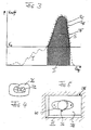
- the force K applied to the tool by the adapter 4 is measured by means of the load cell connected via the line 10 and the path traveled by the adapter 4 (a corresponding displacement sensor is not shown), the force shown by dashed lines in FIG -way characteristic.
- This force-displacement characteristic first passes through a preparation phase I within which the upper tool part 18 comes into firm contact with the Crimpanschlußbauteil 26 and the cable end, and then passes through the actual Vercrimpungsphase II.
- the curve is specific for each type of Crimpanschlußbau former and cables and the tool.
- the actual measurement evaluation takes place to suppress disturbances above a threshold force K S.
- the dotted curve S indicates a setpoint curve, which represents a perfect crimping.
- As a setpoint for detecting a perfect crimping curve S itself can be taken or integrated under the curve S surface F, which is a measure of the Crimparbeit done.
- the data representing the curve S and / or the surface F are stored as desired data by the data processing device provided in the crimping device 2.
- FIG. 4 shows a cross section through a provided with a Crimpanschlußbauteil cable, cut in the stripped wires.
- the crimp connection component 26 is bent overall in the form of a sleeve and clamps the cores 32 of the cable in a form-fitting manner in its interior for secure contacting.
- the tool 14 is provided with a data carrier 36, which is attached to the frame 20 in the example shown.
- the task and function of this volume 36 is as follows: When the tool 14 is first inserted in the crimping device 2, the setpoint data, for example based on the setpoint curve S and / or the integral F, are determined and stored by the data processing device 15 in the crimping device 2, so that they are available as setpoint values for future crimping operations.
- a crimp connection is tested for mechanical strength, electrical resistance and optical quality, and the measurement data of the crimp connection, which has been tested as faultless, is stored as setpoint data in the data processing of the crimping device.
- the desired data of the tool 14 are read from the memory of the data processing device 15 of the crimping device 2 and read into the data carrier 36. In this way, the tool 14 itself carries its specific target data. Furthermore, upon removal of the tool 14, the number of crimp connections made with it can be read into its data carrier 36.
- FIG. 5 shows a data carrier 36 which is inserted into a recess 38 of the frame 20 and has a base plate 40 fastened to the bottom of the recess, on which the actual data carrier is mounted.
- the data carrier 36 is mounted protected on the frame 20.
- the data carrier 36 may be a simple read / write memory which has a mechanically contactable or non-contact readable and readable interface with which data can be read in and out by means of a handheld device.
- the data carrier 36 may include a complete microprocessor with program memory, data memory and input and output device, for example with antenna and transponder.
- the data processing device 15 of the crimping device 2 accordingly has an input and output unit with which the data can be transmitted, for example, by means of a handheld device.
- the crimping device 2 in the area of the tool receiving space 6 on a contacting or contactless interface 46, which is arranged opposite a corresponding formed on the tool 14 according to Figure 3 on the back of the frame 20 interface. It is understood that in this case, advantageously, the entire disk 36 is disposed on the back of the frame 20 via the interfaces automatically when you insert or start up a tool 14 and when removing or decommissioning the tool. It is further understood that a variety of transmission techniques (with contacts, contactless with ultrasound, infrared, antenna with transmitter, etc.) can be applied.
- the invention provides a way to monitor without loss of time and extremely safe the quality of crimp connections made with different tools, with the state of the tools can be detected even predictable.
- the tool-specific desired data stored on the tool itself relate not only to the tool itself, but preferably also to the crimped terminal component and the cable for which the tool is to be used. They do not or only slightly depend on the particular crimping device and may, if necessary, contain a corresponding additional parameter.
- the invention is applicable wherever multiple tools with tool-specific data used for quality control or for controlling a device operating with the tool are alternately used in one or more devices.
Landscapes
- Engineering & Computer Science (AREA)
- Manufacturing & Machinery (AREA)
- Manufacturing Of Electrical Connectors (AREA)
Abstract
Description
Die Erfindung betrifft ein Verfahren zur Qualitätssicherung von in einer Crimpvorrichtung hergestellten Crimpverbindungen gemäß dem Oberbegriff des Anspruchs 1.The invention relates to a method for quality assurance of crimp connections produced in a crimping apparatus according to the preamble of claim 1.
Die Erfindung betrifft weiter ein Crimpwerkzeug gemäß dem Oberbegriff des Anspruchs 3 und eine Crimpvorrichtung gemäß dem Oberbegriff des Anspruchs 6.The invention further relates to a crimping tool according to the preamble of claim 3 and a crimping apparatus according to the preamble of
Eine nach dem gattungsgemäßen Verfahren und mit einem gattungsgemäßen Crimpwerkzeug arbeitende Crimpvorrichtung ist aus der DE 4 038 658 A1 bekannt.A working according to the generic method and a generic crimping crimping apparatus is known from
Für das Anbringen von Steckern an elektrischen Leitungen mit mehreren Leitungsadern und einer isolierenden Ummantelung ist das sogenannte Crimpen weit verbreitet. Dabei wird ein zunächst in Form eines flachen Blechteils ausgebildetes Crimpanschlußbauteil durch Aufeinanderzubewegen zweier relativ zueinander beweglicher, als Stempel ausgebildeter Werkzeugteile um das Leitungsende herum geformt und dann sicher kontaktierend mit dem Leitungsende verbunden. Insbesondere Kabelbäume in Kraftfahrzeugen bestehen aus einer Vielzahl unterschiedlichster elektrischer Leitungen, die durch Crimpen mit Steckern bzw. Crimpanschlußbauteilen versehen werden müssen. Die Qualitätssicherung der Crimpvorgänge erfolgt beispielsweise dadurch, daß während des Crimpens die Kraft-Weg-Kennlinie der Werkzeugteile aufgenommen wird und unmittelbar mit einer Soll-Kraft-Weg-Kennlinie, die in der Crimpvorrichtung gespeichert ist, verglichen wird oder daß aus der gemessenen Kraft-Weg-Kennlinie Meßdaten berechnet werden, die mit den gespeicherten Solldaten verglichen werden. Die Solldaten bzw. die Soll-Kraft-Weg-Kennlinie werden bei der Inbetriebnahme des Werkzeugs ermittelt.For the attachment of plugs on electrical lines with multiple wires and an insulating sheath so-called crimping is widespread. In this case, an initially formed in the form of a flat sheet metal part Crimpanschlußbauteil is formed by moving together two relatively movable, designed as a stamp tool parts around the end of the line around and then connected securely contacting the line end. In particular harnesses in motor vehicles consist of a variety of different electrical lines that must be provided by crimping with plugs or Crimpanschlußbauteilen. The quality assurance of the crimping processes takes place, for example, in that during the crimping the force-displacement characteristic curve of the tool parts is picked up and compared directly with a desired force-displacement characteristic stored in the crimping device or that from the measured force Path characteristic measured data to be compared with the stored target data. The setpoint data or the setpoint force-displacement characteristic are determined during commissioning of the tool.
In der Praxis stellt sich das Problem, daß es eine große Vielzahl sowohl verschiedener Kabel als auch verschiedener Crimpanschlußbauteile gibt, die jeweils den Einsatz unterschiedlicher Werkzeuge erfordern. Diese Werkzeuge können in einer gemeinsamen Crimpvorrichtung verwendet werden und werden jeweils ausgewechselt. Es ist einerseits zeitaufwendig und andererseits teuer, nach jedem Werkzeugwechsel die Solldaten, die eine einwandfreie Crimpung signalisieren, zu ermitteln und zu speichern.In practice, there is the problem that there are a large variety of both different cables and different Crimpanschlußbauteile, each requiring the use of different tools. These tools can be used in a common Crimping device can be used and are replaced each. On the one hand, it is time-consuming and, on the other hand, expensive to determine and store the setpoint data which signal a perfect crimping after each tool change.
Der Erfindung liegt die Aufgabe zugrunde, ein gattungsgemäßes Verfahren dahingehend weiterzubilden, daß bei Betrieb der Crimpvorrichtung mit unterschiedlichen Werkzeugen trotz kurzer Werkzeugwechselzeiten eine einwandfreie Qualität der Crimpverbindungen erzielt wird. Der Erfindung liegt weiter die Aufgabe zugrunde, ein gattungsgemäßes Crimpwerkzeug zur Durchführung des vorgenannten Verfahrens zu schaffen. Weiter liegt der Erfindung die Aufgabe zugrunde, eine Crimpvorrichtung zur Verwendung eines solchen Werkzeugs zu schaffen.The invention has the object of developing a generic method to the effect that during operation of the crimping device with different tools despite short tool change times a perfect quality of the crimped connections is achieved. The invention is further based on the object to provide a generic crimping tool for performing the aforementioned method. It is a further object of the present invention to provide a crimping apparatus for using such a tool.
Der das Verfahren betreffende Teil der Erfindungsaufgabe wird mit den Merkmalen des Hauptanspruchs gelöst.The part of the invention task that concerns the method is solved with the features of the main claim.
Dadurch, daß das Werkzeug mit einem Datenträger versehen wird, der werkzeugspezifische Solldaten trägt und diese Solldaten dann unmittelbar mit den jeweiligen Messdaten verglichen werden, ist nach einem Werkzeugwechsel keine versuchstechnisch aufwendige Ermittlung der Solldaten erforderlich.Characterized in that the tool is provided with a data carrier that carries tool-specific desired data and this target data is then compared directly with the respective measurement data, no experimentally complex determination of the target data is required after a tool change.
Das erfindungsgemäße Verfahren wird mit den Merkmalen des Anspruchs 2 in vorteilhafter Weise weiter gebildet.The inventive method is further formed with the features of
Der Anspruch 3 ist auf das Crimpwerkzeug gerichtet, mit dem der entsprechende Teil der Erfindungsaufgabe gelöst wird.The claim 3 is directed to the crimping tool, with which the corresponding part of the invention task is solved.
Das Crimpwerkzeug des Anspruchs 3 wird mit denen der Ansprüche 4 und 5 in vorteilhafter Weise weitergebildet.The crimping tool of claim 3 is further developed with those of
Der Anspruch 6 kennzeichnet eine Crimpvorrichtung zur Verwendung mit einem erfindungsgemäßen Crimpwerkzeug.The
Die Crimpvorrichtung gemäß dem Anspruch 6 wird mit den Merkmalen der Ansprüche 7 und 8 in vorteilhafter Weise weiter gebildet.The crimping device according to
Die Erfindung wird im folgenden anhand schematischer Zeichnungen beispielsweise und mit weiteren Einzelheiten erläutert.
Es stellen dar:
- Figur 1
- in perspektivischer Darstellung eine Crimpvorrichtung mit ausgebautem Werkzeug,
Figur 2- ein Werkzeug zum Einsatz in der Crimpvorrichtung gemäß Figur 1,
- Figur 3
- eine Kraft-Weg-Kennlinie, wie sie sich beim Zusammenpressen der relativ zueinander beweglichen Werkzeugteile zur Herstellung einer Crimpvorrichtung ergibt,
Figur 4- einen Querschnitt durch eine Crimpverbindung und
- Figur 5
- eine perspektivische Ansicht eines Datenträgers.
They show:
- FIG. 1
- in a perspective view a crimping device with a removed tool,
- FIG. 2
- a tool for use in the crimping apparatus according to FIG. 1,
- FIG. 3
- a force-displacement characteristic, as it results in compressing the relatively movable tool parts for producing a crimping apparatus,
- FIG. 4
- a cross section through a crimp and
- FIG. 5
- a perspective view of a data carrier.
In der vorliegenden Beschreibung sind die Figuren 1 und 2 weitgehend der eingangs genannten DE 4 038 658 A1 entnommen, deren Inhalt als Beispiel für eine Crimpvorrichtung und ein Crimpverfahren zum Inhalt der folgenden Anmeldung gemacht wird.In the present description, Figures 1 and 2 are largely taken from the
Die insgesamt mit 2 bezeichnete Crimpvorrichtung ist durch eine Crimppresse gebildet, bei der ein mittels eines nicht im einzelnen dargestellten Antriebs aufwärts und abwärts bewegbarer Stempel in einem Adapter 4 endet. Der Adapter 4 ragt in einen Werkzeugaufnahmeraum 6 ein, der unten eine Platte 8 aufweist, die sich über eine Kraftmessdose (nur die Leitung 10, die zur Kraftmessdose führt ist dargestellt) an einem Fuß 12 der Crimpvorrichtung 2 abstützt.
Zur Bedienung der Crimpvorrichtung ist ein Bedienfeld 14 vorgesehen, das ein Interface zu einer in der Crimpvorrichtung enthaltenen Datenverarbeitungseinrichtung 15 mit Mikroprozessor, Datenspeicher, Programmspeicher usw. bildet.The generally designated 2 crimping device is formed by a crimping press, in which a means of a drive not shown in detail upwardly and downwardly movable punch in an
To operate the crimping device, a
In den Werkzeugaufnahmeraum 6 der Crimpvorrichtung 2 ist ein in Figur 2 insgesamt mit 14 bezeichnetes Werkzeug einsetzbar.
Dieses Werkzeug enthält ein an den Adapter 4 anschließbares Anschlußbauteil 16, das starr mit einem als Oberstempel ausgebildeten Werkzeugteil 18 verbunden ist und zusammen mit diesem innerhalb eines Gestells 20 auf- und abwärts bewegbar ist.
Dem Werkzeugteil 18 gegenüberliegend angeordnet ist in einem Grundkörper 22 ein weiteres als Unterstempel ausgebildetes Werkzeugteil 24.
Zur Beschickung des Werkzeugs mit zunächst als flache Bleche ausgebildeten Crimpanschlußbauteilen 20 dient eine Beschickungseinrichtung 28, die ein Band 30 mit den Crimpanschlußbauteilen 26 mittels eines beweglich angetriebenen Hebels 32 schrittweise vorwärts bewegt. Wenn auf dem unteren Werkzeugteil 24 ein Crimpanschlußbauteil 26 angeordnet ist, wird zwischen den Werkzeugteilen 18 und 24 ein nicht dargestelltes Kabelende mit abisolierten Leiteradern angeordnet und durch Crimpen fest mit dem Crimpanschlußbauteil 26 verbunden.
Während eines Crimpvorgangs ergibt sich durch Messung der auf das Werkzeug vom Adapter 4 aufgebrachten Kraft K mittels der über die Leitung 10 angeschlossenen Kraftmessdose und des Weges, den der Adapter 4 zurücklegt (ein entsprechender Wegsensor ist nicht dargestellt), die in Figur 3 gestrichelt dargestellte Kraft-Weg-Kennlinie. Diese Kraft-Weg-Kennlinie durchläuft zunächst eine Vorbereitungsphase I innerhalb der das obere Werkzeugteil 18 in feste Anlage an das Crimpanschlußbauteil 26 und das Kabelende kommt, und durchläuft dann die eigentliche Vercrimpungsphase II. Der Kurvenverlauf ist spezifisch für jeweils eine Art von Crimpanschlußbauteilen und Kabeln und das Werkzeug. Die eigentliche Messauswertung erfolgt zur Unterdrückung von Störungen oberhalb einer Schwellkraft KS.
Die gepunktete Kurve S gibt eine Sollkurve an, die eine einwandfreie Crimpung darstellt. Als Sollgrößen zum Erkennen einer einwandfreien Crimpung kann die Kurve S selbst genommen werden oder die unter der Kurve S integrierte Fläche F, die ein Maß für die geleistete Crimparbeit ist. Die die Kurve S und/oder die Fläche F wiedergebenden Daten werden von der in der Crimpvorrichtung 2 vorhandenen Datenverarbeitungseinrichtung als Solldaten gespeichert.In the
This tool includes a connectable to the
Arranged opposite the
To feed the tool with initially formed as a flat sheet
During a crimping operation, the force K applied to the tool by the
The dotted curve S indicates a setpoint curve, which represents a perfect crimping. As a setpoint for detecting a perfect crimping curve S itself can be taken or integrated under the curve S surface F, which is a measure of the Crimparbeit done. The data representing the curve S and / or the surface F are stored as desired data by the data processing device provided in the
Bei einem Crimpvorgang werden die Istdaten erfaßt und mit den Solldaten verglichen. Bei einer Abweichung der Kraft-Weg-Kennlinie von der Solllinie nach unten (SI) oder nach oben (SII) erfolgt eine Fehleranzeige. Für das Erkennen einer fehlerhaften Crimpung können auch weitere Kriterien herangezogen werden, wie eine zu große Abweichung eines einzelnen Meßpunktes, zusätzliche Messungen von Zeitdauern u.s.w..
Figur 4 zeigt einen Querschnitt durch ein mit einem Crimpanschlußbauteil versehenes Kabel, geschnitten im Bereich der abisolierten Adern. Ersichtlich ist das Crimpanschlußbauteil 26 insgesamt hülsenförmig verbogen und klemmt die Adern 32 des Kabels für eine sichere Kontaktierung formschlüssig in seinem Inneren ein.In a crimping process, the actual data are detected and compared with the desired data. In a deviation of the force-displacement curve from the target line down (S I ) or upwards (S II ) is an error display. For the detection of a faulty crimping also other criteria can be used, such as a too large deviation of a single measuring point, additional measurements of periods, etc.
Figure 4 shows a cross section through a provided with a Crimpanschlußbauteil cable, cut in the stripped wires. As can be seen, the
Die bisher beschriebene Vorrichtung und das bisher beschriebene Verfahren sind aus der DE 4 038 658 A1 bekannt und wurden daher nur pauschal beschrieben.
Wie erläutert müssen für unterschiedliche Crimpverbindungen unterschiedliche Werkzeuge 14 in der Crimpvorrichtung 2 verwendet werden. Erfingungsgemäß ist das Werkzeug 14 mit einem Datenträger 36 versehen, der im dargestelltem Beispiel an dem Gestell 20 angebracht ist. Die Aufgabe und Funktion dieses Datenträgers 36 ist folgende:
Wenn das Werkzeug 14 erstmalig in der Crimpvorrichtung 2 eingesetzt wird, werden von der in der Crimpvorrichtung 2 vorhandenen Datenverarbeitungseinrichtung 15 die Solldaten beispielsweise anhand der Sollkurve S und/oder des Integrals F ermittelt und gespeichert, sodaß sie als Sollwerte für zukünftige Crimpvorgänge zur Verfügung stehen. Dazu wird beispielsweise eine Crimpverbindung auf mechanische Festigkeit, elektrischen Widerstand und optische Qualität geprüft und die Meßdaten der als einwandfrei geprüften Crimpverbindung als Solldaten in der Datenverarbeitungs der Crimpvorrichtung gespeichert. Bevor das Werkzeug 14 aus der Crimpvorrichtung 2 entfernt wird, um durch ein anderes Werkzeug ersetzt zu werden, werden die Solldaten des Werkzeugs 14 aus dem Speicher der Datenverarbeitungseinrichtung 15 der Crimpvorrichtung 2 ausgelesen und in den Datenträger 36 eingelesen. Auf diese Weise trägt das Werkzeug 14 selbst seine spezifischen Solldaten. Des weiteren kann bei der Entnahme des Werkzeugs 14 die Anzahl der mit ihm hergestellten Crimpverbindungen in seinen Datenträger 36 eingelesen werden. Wird das Werkzeug 14 nun erneut in Betrieb genommen, so können seine Solldaten vom Datenträger 36 ausgelesen und in den Speicher der Datenverarbeitungseinrichtung 15 der Crimpvorrichtung 2 eingelesen werden, so daß die Solldaten sofort zur Verfügung stehen. Es wird nun mit üblicher Geschwindigkeit ein erster Crimpvorgang ausgeführt, wobei sofort festgestellt werden kann, ob dieser Crimpvorgang in Ordnung ist oder nicht.
Für die Ausbildung des Datenträgers 36 und für die Datenübertragung vom Datenträger 36 in die Datenverarbeitungseinrichtung 15 der Crimpvorrichtung 2 gibt es die unterschiedlichsten Ausführungsformen.
Figur 5 zeigt einen in eine Ausnehmung 38 des Gestells 20 eingesetzen Datenträger 36, der eine am Boden der Ausnehmung befestigte Grundplatte 40 aufweist, auf der der eigentliche Datenträger angebracht ist. Auf diese Weise ist der Datenträger 36 geschützt an dem Gestell 20 angebracht.
Der Datenträger 36 kann ein einfacher Schreib-/Lesespeicher sein, der über ein mechanisch kontaktierbares oder berührungsloses ein-und auslesbares Interface verfügt, mit dem Daten mittels eines Handgerätes ein- und auslesbar sind. Bei aufwendiger Ausführung kann der Datenträger 36 einen vollständigen Mikroprozessor mit Programmspeicher, Datenspeicher und Ein- und Ausgabevorrichtung, beispielsweise mit Antenne und Transponder, enthalten.
Die Datenverarbeitungseinrichtung 15 der Crimpvorrichtung 2 weist entsprechend eine Ein- und Ausgabeeinheit auf, mit der die Daten beispielsweise mittels eines Handgerätes übertragbar sind. In komfortablerer und betriebssicherer Ausführung weist die Crimpvorrichtung 2 im Bereich des Werkzeugaufnahmeraums 6 eine mit Kontaktierung oder berühungslos arbeitende Schnittstelle 46 auf, die einer entsprechenden am Werkzeug 14 gemäß Figur 3 auf der Rückseite des Gestells 20 ausgebildeten Schnittstelle gegenüberliegend angeordnet ist. Über die Schnittstellen erfolgt automatisch ein Datenaustauch beim Einsetzen bzw. der Inbetriebnahme eines Werkzeugs 14 und beim Herausnehmen bzw. der Außerbetriebnahme des Werkzeugs 14. Es versteht sich, daß in diesem Fall vorteilhafterweise der gesamte Datenträger 36 an der Rückseite des Gestells 20 angeordnet ist. Es versteht sich weiter, daß unterschiedlichste Übertragungstechniken (mit Kontakten, kontaktlos mit Ultraschall, Infrarot, über Antenne mit Sender usw.) angewendet werden können. Bei über Funk erfolgenden Übertragungen bestehen bezüglich der räumlichen Anordnung des Datenträges und der Ein- und Ausgabeeinrichtung der Datenübertragungseinrichtung der Crimpvorrichtung 2 kaum räumliche Beschränkungen.
In den Datenträger 36 des Werkzeugs 14 können bei einer Außerbetriebnahme des Werkzeugs 14 Solldaten eingelesen werden, die beispielsweise dem Mittelwert einer bestimmten Anzahl von Messdaten entsprechen. Das Werkzeug kann in einer zentralen Werkzeugverwaltung dann anhand dieser Daten und im Vergleich mit den ursprünglichen Solldaten sowie gegebenenfalls der Anzahl der insgesamt mit dem Werkzeug hergestellten Crimpverbindungen auf weitere Funktionstauglichkeit und Lebensdauer überprüft werden.
Es versteht sich, daß die Erfindung für unterschiedlichste Crimpvorrichtungen bzw. Crimppressen und Werkzeuge einsetzbar ist. Beispielsweise kann der Umfang eines Werkzeugs erheblich kleiner als der der Figur 2 sein. In speziellen Ausführungen beispielsweise können nur die Werkzeugteile 18 und 24 ausgewechselt werden. Dann trägt eines dieser Werkzeugteile den Datenträger.
Insgesamt ist mit der Erfindung eine Möglichkeit geschaffen, ohne Zeitverluste und außerordentlich sicher die Qualität von mit unterschiedlichsten Werkzeugen hergestellten Crimpverbindungen zu überwachen, wobei auch der Zustand der Werkzeuge selbst prognostizierbar erfaßt werden kann. Die werkzeugspezifischen an dem Werkzeug selbst gespeicherten Solldaten beziehen sich nicht nur auf das Werkzeug selbst, sondern vorzugsweise auch auf das Crimpanschlußbauteil und das Kabel, für das das Werkzeug verwendet werden soll. Sie hängen nicht oder nur schwach von der jeweiligen Crimpvorrichtung ab und können erforderlichenfalls einen entsprechenden, zusätzlichen Parameter enthalten. Die Erfindung ist überall dort anwendbar, wo mehrere Werkzeuge mit werkzeugspezifischen Daten, die zur Qualitätsüberwachung oder zur Steuerung einer mit dem Werkzeug arbeitenden Vorrichtung dienen, in einer oder mehreren Vorrichtungen abwechselnd eingesetzt werden.The device described so far and the method described so far are known from
As explained,
When the
For the formation of the
FIG. 5 shows a
The
The
Into the
It is understood that the invention can be used for a wide variety of crimping devices or crimping presses and tools. For example, the circumference of a tool can be considerably smaller than that of FIG. In special embodiments, for example, only the
Overall, the invention provides a way to monitor without loss of time and extremely safe the quality of crimp connections made with different tools, with the state of the tools can be detected even predictable. The tool-specific desired data stored on the tool itself relate not only to the tool itself, but preferably also to the crimped terminal component and the cable for which the tool is to be used. They do not or only slightly depend on the particular crimping device and may, if necessary, contain a corresponding additional parameter. The invention is applicable wherever multiple tools with tool-specific data used for quality control or for controlling a device operating with the tool are alternately used in one or more devices.
Claims (8)
- A method for quality assurance of crimp connections made by a crimping device, which crimp connections are made by fastening a crimp connector (26) to an end of a cable between two relatively to one another movable tool parts (18, 24) of a tool (14) insertable into the crimping device (2), when the two tool parts are moved towards one another,
wherein the quality of the crimp connection is monitored by comparing measured data which are derived from a force-stroke characteristic line of the two relative to one another movable tool parts measured during the crimping operation, with stored nominal data,
characterized by
providing the tool (14) with an electronic data storage device (36), which carries tool specific nominal data, and comparing said tool specific nominal data with the respective measured data. - A method according to claim 1 characterized in that before removing a tool (14) from the crimping device (2) data corresponding to the crimping operations performed previously are stored in the electronic data storage device (36) of the tool (14).
- Crimping tool to be used in a crimping device,
which crimping tool (14) includes two tool parts (18, 24) being relatively movable to one another and serving for making a crimp connection between a crimp connector (26) and an end of a cable,
characterized by an electronic data storage device (36) mounted to said tool (14) and carrying tool specific data. - Crimping tool according to claim 3,
characterized in that the electronic data storage device (36) carries a force-stroke characteristic line associated to the tool (14). - Crimping tool according to claim 3 or 4,
characterized in that the electronic data storage device (36) includes a means adapted to read in and store new data and a means adapted to read out the stored data. - Crimping device to be used with a crimping tool according to any of claims 3 to 5, including sensors for sensing measured variables during a crimping operation, a data processing means (15) for processing the output signals of said sensors into measured data and for comparing the measured data with nominal data stored in a storage,
characterized by
a data transmission device (46) for transmitting nominal data stored in said electronic data storage device (36) of the tool to the storage of the data processing means (15). - Crimping device according to claim 6,
characterized in that the data processing means (15) detects the number of crimp operations performed with a tool (14) and transmits said number in its data storage. - Crimping device according to claim 6 or 7,
characterized in that said data processing means (15) transmits measured data into the data storage of the tool (14).
Applications Claiming Priority (2)
| Application Number | Priority Date | Filing Date | Title |
|---|---|---|---|
| DE19843156 | 1998-09-21 | ||
| DE19843156A DE19843156A1 (en) | 1998-09-21 | 1998-09-21 | Process for quality assurance of crimp connections produced in a crimping device, as well as crimping tool and crimping device |
Publications (3)
| Publication Number | Publication Date |
|---|---|
| EP0989636A2 EP0989636A2 (en) | 2000-03-29 |
| EP0989636A3 EP0989636A3 (en) | 2002-05-22 |
| EP0989636B1 true EP0989636B1 (en) | 2006-01-04 |
Family
ID=7881647
Family Applications (1)
| Application Number | Title | Priority Date | Filing Date |
|---|---|---|---|
| EP99117658A Expired - Lifetime EP0989636B1 (en) | 1998-09-21 | 1999-09-07 | Quality assuring process for in a crimping device made crimped connection as well as a crimping tool and crimping device |
Country Status (4)
| Country | Link |
|---|---|
| US (1) | US6418769B1 (en) |
| EP (1) | EP0989636B1 (en) |
| AT (1) | ATE315283T1 (en) |
| DE (2) | DE19843156A1 (en) |
Cited By (2)
| Publication number | Priority date | Publication date | Assignee | Title |
|---|---|---|---|---|
| DE102006014521A1 (en) | 2006-03-29 | 2008-10-09 | Schäfer Werkzeug- und Sondermaschinenbau GmbH | crimping |
| EP2698885A1 (en) | 2012-08-15 | 2014-02-19 | Wezag GmbH Werkzeugfabrik | Change adapter for a crimping machine |
Families Citing this family (37)
| Publication number | Priority date | Publication date | Assignee | Title |
|---|---|---|---|---|
| DE50008512D1 (en) * | 2000-08-11 | 2004-12-09 | Delphi Tech Inc | fastening device |
| DE10041237B4 (en) * | 2000-08-22 | 2006-02-02 | Engberts & Schäfer GmbH | Method and device for detecting machine quality on stop presses |
| US7324864B2 (en) | 2001-06-15 | 2008-01-29 | Smithkline Beecham Corporation | Apparatus and method for measuring forces imparted on valve assemblies of metered dose delivery containers during manufacture thereof |
| DE10232470A1 (en) * | 2002-07-17 | 2004-02-05 | Bernhard Schäfer Werkzeug- und Sondermaschinenbau GmbH | Method and device for quality assurance of crimp connections |
| JP3935034B2 (en) * | 2002-09-17 | 2007-06-20 | 矢崎総業株式会社 | Design support system |
| JP4436053B2 (en) * | 2003-02-13 | 2010-03-24 | 矢崎総業株式会社 | Crimping terminal state estimation device and crimping terminal pass / fail judgment device |
| US6971273B2 (en) * | 2003-05-30 | 2005-12-06 | The Boeing Company | Tool evaluation system and method |
| WO2004109461A2 (en) * | 2003-06-04 | 2004-12-16 | Zusi Christopher J | Automated machine setup with modular tooling |
| US7159440B2 (en) * | 2003-06-26 | 2007-01-09 | The Boeing Company | Tool evaluation calibrator and method |
| DE502004005315D1 (en) * | 2003-09-10 | 2007-12-06 | Komax Holding Ag | Wire-processing device |
| EP1515403B1 (en) * | 2003-09-10 | 2007-10-24 | komax Holding AG | Cable processing apparatus |
| US7181942B2 (en) * | 2004-03-02 | 2007-02-27 | The United States Of America As Represented By The Administrator Of The National Aeronautics And Space Administration | Device and method for connections made between a crimp connector and wire |
| EP1764881B1 (en) * | 2005-09-19 | 2008-07-16 | komax Holding AG | Crimping device |
| US20070129822A1 (en) * | 2005-12-05 | 2007-06-07 | Tyco Electronics Corporation | Methods and systems for operating a termination machine |
| US8746026B2 (en) * | 2008-10-02 | 2014-06-10 | Komax Holding Ag | Method for determining the quality of a crimped connection between a conductor and a contact |
| JP5587400B2 (en) | 2009-04-09 | 2014-09-10 | シュロニガー ホールディング アーゲー | Crimping process monitoring method, crimping press and computer program product |
| US8904616B2 (en) | 2009-04-09 | 2014-12-09 | Schleuniger Holding Ag | Method of monitoring a crimping process, crimping press and computer program product |
| EP2378615A1 (en) * | 2010-04-13 | 2011-10-19 | Schleuniger Holding AG | Crimp press |
| WO2012106390A2 (en) | 2011-02-01 | 2012-08-09 | United States Of America As Represented By The Administrator Of The National Aeronautics And Space Administration | Process and apparatus for nondestructive evaluation of the quality of a crimped wire connector |
| DE102011004298A1 (en) * | 2011-02-17 | 2012-08-23 | Robert Bosch Gmbh | Process and device for the quality assurance production a crimping |
| US8570536B2 (en) | 2011-06-08 | 2013-10-29 | Daniels Manufacturing Corporation | Smart crimp tool system for electrical contacts and terminals which are controlled and monitored by a central database manager |
| BR112014007626A2 (en) * | 2011-09-29 | 2017-04-11 | Schleuniger Holding Ag | method for attaching a sealed cable, sealing transfer unit or comparable cable gland components to a cable processing installation, and cable gland transfer process |
| US8875580B2 (en) | 2011-12-13 | 2014-11-04 | The United States Of America As Represented By The Adminstrator Of The National Aeronautics And Space Adminstration | Method and apparatus to detect wire pathologies near crimped connector |
| US8914961B2 (en) * | 2012-02-29 | 2014-12-23 | GM Global Technology Operations LLC | Methods and systems for measuring crimp quality |
| US9003645B1 (en) | 2013-01-17 | 2015-04-14 | The United States Of America As Represented By The Administrator Of The National Aeronautics And Space Administration | Ultrasonic device for assessing the quality of a wire crimp |
| DE102013211045A1 (en) * | 2013-06-13 | 2014-12-18 | Otto Bihler Handels-Beteiligungs-Gmbh | Forming method with control of a geometric property of a workpiece and device thereto |
| US10153606B2 (en) | 2014-10-10 | 2018-12-11 | The United States Of America As Represented By The Administrator Of Nasa | Method to control crimping processes using ultrasonic transmission analysis |
| US10444051B2 (en) | 2017-01-09 | 2019-10-15 | Georg Fischer Signet, LLC | Ultrasonic sensor assembly and method of manufacture |
| US10254143B2 (en) | 2017-01-13 | 2019-04-09 | Georg Fischer Signet Llc | Fluid-flow sensor assembly having reinforced body |
| EP3360622B1 (en) * | 2017-02-13 | 2020-11-04 | FELSS Systems GmbH | Method of manufacturing and forming machine for forming in particular metallic workpieces by extrusion |
| US10581213B2 (en) * | 2017-04-25 | 2020-03-03 | Te Connectivity Corporation | Crimp tooling having guide surfaces |
| US10620060B2 (en) | 2017-07-19 | 2020-04-14 | Georg Fischer Signet, LLC | Combined ultrasonic temperature and conductivity sensor assembly |
| US10302474B2 (en) | 2017-08-09 | 2019-05-28 | Georg Fischer Signet Llc | Insertion ultrasonic sensor assembly |
| CA3090253C (en) | 2018-01-31 | 2023-02-21 | Abb Schweiz Ag | Crimping tool with wireless communication system |
| US11621531B2 (en) | 2018-09-28 | 2023-04-04 | Hubbell Incorporated | Power tool with crimp localization |
| DE102018218371A1 (en) * | 2018-10-26 | 2020-04-30 | Schäfer Werkzeug- und Sondermaschinenbau GmbH | Method for monitoring a crimping device, monitoring unit and crimping device |
| CN110146439A (en) * | 2019-04-26 | 2019-08-20 | 国网河北能源技术服务有限公司 | A kind of cable compression joint performance test platform and its test method |
Family Cites Families (18)
| Publication number | Priority date | Publication date | Assignee | Title |
|---|---|---|---|---|
| AT190569B (en) * | 1948-01-16 | 1957-07-10 | Aircraft Marine Prod Inc | Machine for attaching connectors, in particular cable lugs, to electrical conductors |
| US4294006A (en) * | 1979-10-18 | 1981-10-13 | General Electric Company | Automatic control for wire crimping machine |
| US4611484A (en) * | 1984-12-10 | 1986-09-16 | Amp Incorporated | Quick change mounting plate |
| US4914602A (en) | 1987-05-13 | 1990-04-03 | Furukawa Electric Co., Ltd. | Method for detecting the molding defectiveness of a press-molded workpiece and a terminal press-bonding apparatus utilizing the same |
| DE3842009C1 (en) * | 1988-11-22 | 1990-03-22 | Kabelwerke Reinshagen Gmbh, 5600 Wuppertal, De | |
| DE4014221A1 (en) * | 1989-05-12 | 1990-11-15 | Siemens Ag | Production monitoring of crimped electrical connectors - using built in strain gauge to measure load as indication of crimping quality |
| GB8914502D0 (en) * | 1989-06-23 | 1989-08-09 | Amp Gmbh | Electrical lead terminating installation |
| GB8927466D0 (en) * | 1989-12-05 | 1990-02-07 | Amp Gmbh | Electrical terminal crimping apparatus |
| GB8927467D0 (en) * | 1989-12-05 | 1990-02-07 | Amp Gmbh | Crimped connection quality control |
| US5197186A (en) * | 1990-05-29 | 1993-03-30 | Amp Incorporated | Method of determining the quality of a crimped electrical connection |
| US5195042A (en) * | 1990-06-27 | 1993-03-16 | Burndy Corporation | Apparatus and method for controlling crimping of articles |
| US5101651A (en) * | 1991-02-22 | 1992-04-07 | Amp Incorporated | Apparatus for determining the force imposed on a terminal during crimping thereof |
| DE4111404A1 (en) * | 1991-04-09 | 1992-10-15 | Rittmeyer Kg | Crimping press for electric cable attachment to plug - has piezoelectric elements encapsulated under impressed surface for maintenance or interruption of eccentric drive of die |
| US5727409A (en) * | 1994-12-28 | 1998-03-17 | Yazaki Corporation | Method of controlling a terminal crimping apparatus |
| US5937505A (en) * | 1995-03-02 | 1999-08-17 | The Whitaker Corporation | Method of evaluating a crimped electrical connection |
| JPH1050449A (en) * | 1996-07-31 | 1998-02-20 | Yazaki Corp | Terminal crimp device |
| CH693550A5 (en) * | 1997-06-30 | 2003-09-30 | Komax Holding Ag | Crimping device and method for its operation. |
| US6047579A (en) * | 1998-04-17 | 2000-04-11 | The Minster Machine Company | RF tag attached to die assembly for use in press machine |
-
1998
- 1998-09-21 DE DE19843156A patent/DE19843156A1/en not_active Withdrawn
-
1999
- 1999-09-07 EP EP99117658A patent/EP0989636B1/en not_active Expired - Lifetime
- 1999-09-07 AT AT99117658T patent/ATE315283T1/en not_active IP Right Cessation
- 1999-09-07 DE DE59913010T patent/DE59913010D1/en not_active Expired - Lifetime
- 1999-09-21 US US09/404,270 patent/US6418769B1/en not_active Expired - Lifetime
Cited By (3)
| Publication number | Priority date | Publication date | Assignee | Title |
|---|---|---|---|---|
| DE102006014521A1 (en) | 2006-03-29 | 2008-10-09 | Schäfer Werkzeug- und Sondermaschinenbau GmbH | crimping |
| EP2698885A1 (en) | 2012-08-15 | 2014-02-19 | Wezag GmbH Werkzeugfabrik | Change adapter for a crimping machine |
| US10862258B2 (en) | 2012-08-15 | 2020-12-08 | Wezag Gmbh Werkzeugfabrik | Set of interchangeable crimp units |
Also Published As
| Publication number | Publication date |
|---|---|
| EP0989636A2 (en) | 2000-03-29 |
| DE19843156A1 (en) | 2000-04-20 |
| ATE315283T1 (en) | 2006-02-15 |
| EP0989636A3 (en) | 2002-05-22 |
| DE59913010D1 (en) | 2006-03-30 |
| US6418769B1 (en) | 2002-07-16 |
Similar Documents
| Publication | Publication Date | Title |
|---|---|---|
| EP0989636B1 (en) | Quality assuring process for in a crimping device made crimped connection as well as a crimping tool and crimping device | |
| DE69117351T2 (en) | Method for determining the quality of a crimp connection | |
| EP2683561B1 (en) | Wear detection system and method | |
| DE29806179U1 (en) | Crimping tool | |
| DE102004004572B4 (en) | Fault diagnosis method for a vehicle communication network | |
| DE4337796A1 (en) | Method for monitoring the quality of crimped joints | |
| EP2122783B1 (en) | Sensor module with a plug-type connector coupling | |
| EP1469958B1 (en) | Placing tool with means for controlling placing processes | |
| DE102006030929A1 (en) | Piston / Cylinder Unit with Diagnostic Unit | |
| DE60020304T2 (en) | Arrangement and method for checking the crimp quality of contacts and method for determining the friction wear of the Crimpmatritze | |
| DE19507959C1 (en) | Current measuring device for automobile onboard supply network | |
| EP2701018B1 (en) | Method for securely adjusting the parameters of a field device | |
| EP3307468B1 (en) | Automatic bond force calibration | |
| DE10130215B4 (en) | Measuring sensor with connected data memory | |
| WO1991002256A1 (en) | Process and device for polling control unit data | |
| DE10306231A1 (en) | Electronic intermediate components for recording data for a peripheral unit transmit recorded data to a position-measuring device | |
| EP1410051B1 (en) | Method and device for checking for errors in electrical lines and/or electrical consumers in a vehicle | |
| EP1764883B1 (en) | System for processing a cable with at least two tools | |
| DE10025760B4 (en) | Accumulation conveyor with programmable sensor unit | |
| WO2019076952A1 (en) | Electrical energy store and method for identifying a storage module type of an electrical energy store | |
| EP1772707A2 (en) | Measuring device | |
| DE10142273A1 (en) | measuring data | |
| WO2016205846A1 (en) | Method for calculating a usage figure for a pressing tool in a joining press | |
| WO2011095258A1 (en) | Position control element | |
| DE102006027551B4 (en) | Method for recording vehicle information during vehicle production for test purposes, and device suitable therefor |
Legal Events
| Date | Code | Title | Description |
|---|---|---|---|
| PUAI | Public reference made under article 153(3) epc to a published international application that has entered the european phase |
Free format text: ORIGINAL CODE: 0009012 |
|
| AK | Designated contracting states |
Kind code of ref document: A2 Designated state(s): AT BE CH CY DE DK ES FI FR GB GR IE IT LI LU MC NL PT SE |
|
| AX | Request for extension of the european patent |
Free format text: AL;LT;LV;MK;RO;SI |
|
| PUAL | Search report despatched |
Free format text: ORIGINAL CODE: 0009013 |
|
| AX | Request for extension of the european patent |
Free format text: AL;LT;LV;MK;RO;SI |
|
| 17P | Request for examination filed |
Effective date: 20021107 |
|
| AKX | Designation fees paid |
Designated state(s): AT BE CH CY DE DK ES FI FR GB GR IE IT LI LU MC NL PT SE |
|
| GRAP | Despatch of communication of intention to grant a patent |
Free format text: ORIGINAL CODE: EPIDOSNIGR1 |
|
| GRAS | Grant fee paid |
Free format text: ORIGINAL CODE: EPIDOSNIGR3 |
|
| GRAA | (expected) grant |
Free format text: ORIGINAL CODE: 0009210 |
|
| AK | Designated contracting states |
Kind code of ref document: B1 Designated state(s): AT BE CH CY DE DK ES FI FR GB GR IE IT LI LU MC NL PT SE |
|
| PG25 | Lapsed in a contracting state [announced via postgrant information from national office to epo] |
Ref country code: NL Free format text: LAPSE BECAUSE OF FAILURE TO SUBMIT A TRANSLATION OF THE DESCRIPTION OR TO PAY THE FEE WITHIN THE PRESCRIBED TIME-LIMIT Effective date: 20060104 Ref country code: IT Free format text: LAPSE BECAUSE OF FAILURE TO SUBMIT A TRANSLATION OF THE DESCRIPTION OR TO PAY THE FEE WITHIN THE PRESCRIBED TIME-LIMIT;WARNING: LAPSES OF ITALIAN PATENTS WITH EFFECTIVE DATE BEFORE 2007 MAY HAVE OCCURRED AT ANY TIME BEFORE 2007. THE CORRECT EFFECTIVE DATE MAY BE DIFFERENT FROM THE ONE RECORDED. Effective date: 20060104 Ref country code: IE Free format text: LAPSE BECAUSE OF FAILURE TO SUBMIT A TRANSLATION OF THE DESCRIPTION OR TO PAY THE FEE WITHIN THE PRESCRIBED TIME-LIMIT Effective date: 20060104 Ref country code: GB Free format text: LAPSE BECAUSE OF FAILURE TO SUBMIT A TRANSLATION OF THE DESCRIPTION OR TO PAY THE FEE WITHIN THE PRESCRIBED TIME-LIMIT Effective date: 20060104 Ref country code: FI Free format text: LAPSE BECAUSE OF FAILURE TO SUBMIT A TRANSLATION OF THE DESCRIPTION OR TO PAY THE FEE WITHIN THE PRESCRIBED TIME-LIMIT Effective date: 20060104 |
|
| RAP1 | Party data changed (applicant data changed or rights of an application transferred) |
Owner name: SLE ELECTRONIC GMBH |
|
| REG | Reference to a national code |
Ref country code: GB Ref legal event code: FG4D Free format text: NOT ENGLISH |
|
| REG | Reference to a national code |
Ref country code: CH Ref legal event code: EP |
|
| REG | Reference to a national code |
Ref country code: IE Ref legal event code: FG4D Free format text: LANGUAGE OF EP DOCUMENT: GERMAN |
|
| REG | Reference to a national code |
Ref country code: CH Ref legal event code: NV Representative=s name: E. BLUM & CO. PATENTANWAELTE |
|
| REF | Corresponds to: |
Ref document number: 59913010 Country of ref document: DE Date of ref document: 20060330 Kind code of ref document: P |
|
| PG25 | Lapsed in a contracting state [announced via postgrant information from national office to epo] |
Ref country code: SE Free format text: LAPSE BECAUSE OF FAILURE TO SUBMIT A TRANSLATION OF THE DESCRIPTION OR TO PAY THE FEE WITHIN THE PRESCRIBED TIME-LIMIT Effective date: 20060404 Ref country code: DK Free format text: LAPSE BECAUSE OF FAILURE TO SUBMIT A TRANSLATION OF THE DESCRIPTION OR TO PAY THE FEE WITHIN THE PRESCRIBED TIME-LIMIT Effective date: 20060404 |
|
| PG25 | Lapsed in a contracting state [announced via postgrant information from national office to epo] |
Ref country code: ES Free format text: LAPSE BECAUSE OF FAILURE TO SUBMIT A TRANSLATION OF THE DESCRIPTION OR TO PAY THE FEE WITHIN THE PRESCRIBED TIME-LIMIT Effective date: 20060415 |
|
| PG25 | Lapsed in a contracting state [announced via postgrant information from national office to epo] |
Ref country code: PT Free format text: LAPSE BECAUSE OF FAILURE TO SUBMIT A TRANSLATION OF THE DESCRIPTION OR TO PAY THE FEE WITHIN THE PRESCRIBED TIME-LIMIT Effective date: 20060605 |
|
| NLV1 | Nl: lapsed or annulled due to failure to fulfill the requirements of art. 29p and 29m of the patents act | ||
| GBV | Gb: ep patent (uk) treated as always having been void in accordance with gb section 77(7)/1977 [no translation filed] |
Effective date: 20060104 |
|
| REG | Reference to a national code |
Ref country code: IE Ref legal event code: FD4D |
|
| PG25 | Lapsed in a contracting state [announced via postgrant information from national office to epo] |
Ref country code: MC Free format text: LAPSE BECAUSE OF NON-PAYMENT OF DUE FEES Effective date: 20060930 Ref country code: BE Free format text: LAPSE BECAUSE OF NON-PAYMENT OF DUE FEES Effective date: 20060930 |
|
| PLBE | No opposition filed within time limit |
Free format text: ORIGINAL CODE: 0009261 |
|
| STAA | Information on the status of an ep patent application or granted ep patent |
Free format text: STATUS: NO OPPOSITION FILED WITHIN TIME LIMIT |
|
| 26N | No opposition filed |
Effective date: 20061005 |
|
| EN | Fr: translation not filed | ||
| REG | Reference to a national code |
Ref country code: CH Ref legal event code: PFA Owner name: SLE ELECTRONIC GMBH Free format text: SLE ELECTRONIC GMBH#JOSEF-BUCHINGER-STRASSE 9#94481 GRAFENAU (DE) -TRANSFER TO- SLE ELECTRONIC GMBH#JOSEF-BUCHINGER-STRASSE 9#94481 GRAFENAU (DE) |
|
| PG25 | Lapsed in a contracting state [announced via postgrant information from national office to epo] |
Ref country code: AT Free format text: LAPSE BECAUSE OF NON-PAYMENT OF DUE FEES Effective date: 20060907 |
|
| BERE | Be: lapsed |
Owner name: SLE ELECTRONIC G.M.B.H. Effective date: 20060930 |
|
| PG25 | Lapsed in a contracting state [announced via postgrant information from national office to epo] |
Ref country code: GR Free format text: LAPSE BECAUSE OF FAILURE TO SUBMIT A TRANSLATION OF THE DESCRIPTION OR TO PAY THE FEE WITHIN THE PRESCRIBED TIME-LIMIT Effective date: 20060405 Ref country code: FR Free format text: LAPSE BECAUSE OF FAILURE TO SUBMIT A TRANSLATION OF THE DESCRIPTION OR TO PAY THE FEE WITHIN THE PRESCRIBED TIME-LIMIT Effective date: 20070223 |
|
| PG25 | Lapsed in a contracting state [announced via postgrant information from national office to epo] |
Ref country code: LU Free format text: LAPSE BECAUSE OF NON-PAYMENT OF DUE FEES Effective date: 20060907 |
|
| PG25 | Lapsed in a contracting state [announced via postgrant information from national office to epo] |
Ref country code: FR Free format text: LAPSE BECAUSE OF FAILURE TO SUBMIT A TRANSLATION OF THE DESCRIPTION OR TO PAY THE FEE WITHIN THE PRESCRIBED TIME-LIMIT Effective date: 20060104 Ref country code: CY Free format text: LAPSE BECAUSE OF FAILURE TO SUBMIT A TRANSLATION OF THE DESCRIPTION OR TO PAY THE FEE WITHIN THE PRESCRIBED TIME-LIMIT Effective date: 20060104 |
|
| PGFP | Annual fee paid to national office [announced via postgrant information from national office to epo] |
Ref country code: CH Payment date: 20140922 Year of fee payment: 16 |
|
| PGFP | Annual fee paid to national office [announced via postgrant information from national office to epo] |
Ref country code: DE Payment date: 20150904 Year of fee payment: 17 |
|
| REG | Reference to a national code |
Ref country code: CH Ref legal event code: PL |
|
| PG25 | Lapsed in a contracting state [announced via postgrant information from national office to epo] |
Ref country code: LI Free format text: LAPSE BECAUSE OF NON-PAYMENT OF DUE FEES Effective date: 20150930 Ref country code: CH Free format text: LAPSE BECAUSE OF NON-PAYMENT OF DUE FEES Effective date: 20150930 |
|
| REG | Reference to a national code |
Ref country code: DE Ref legal event code: R119 Ref document number: 59913010 Country of ref document: DE |
|
| PG25 | Lapsed in a contracting state [announced via postgrant information from national office to epo] |
Ref country code: DE Free format text: LAPSE BECAUSE OF NON-PAYMENT OF DUE FEES Effective date: 20170401 |