EP1211435A2 - Planetary gear reduction device with torque limiter function - Google Patents
Planetary gear reduction device with torque limiter function Download PDFInfo
- Publication number
- EP1211435A2 EP1211435A2 EP01310096A EP01310096A EP1211435A2 EP 1211435 A2 EP1211435 A2 EP 1211435A2 EP 01310096 A EP01310096 A EP 01310096A EP 01310096 A EP01310096 A EP 01310096A EP 1211435 A2 EP1211435 A2 EP 1211435A2
- Authority
- EP
- European Patent Office
- Prior art keywords
- gear
- output shaft
- planetary
- planetary gear
- housing
- Prior art date
- Legal status (The legal status is an assumption and is not a legal conclusion. Google has not performed a legal analysis and makes no representation as to the accuracy of the status listed.)
- Granted
Links
- 230000009467 reduction Effects 0.000 title claims abstract description 63
- 230000005540 biological transmission Effects 0.000 claims abstract description 22
- 230000007246 mechanism Effects 0.000 claims abstract description 21
- 230000009471 action Effects 0.000 claims abstract description 4
- 230000006835 compression Effects 0.000 claims description 32
- 238000007906 compression Methods 0.000 claims description 32
- 230000003247 decreasing effect Effects 0.000 description 3
- 230000004048 modification Effects 0.000 description 2
- 238000012986 modification Methods 0.000 description 2
- 230000000694 effects Effects 0.000 description 1
Images



Classifications
-
- F—MECHANICAL ENGINEERING; LIGHTING; HEATING; WEAPONS; BLASTING
- F16—ENGINEERING ELEMENTS AND UNITS; GENERAL MEASURES FOR PRODUCING AND MAINTAINING EFFECTIVE FUNCTIONING OF MACHINES OR INSTALLATIONS; THERMAL INSULATION IN GENERAL
- F16D—COUPLINGS FOR TRANSMITTING ROTATION; CLUTCHES; BRAKES
- F16D7/00—Slip couplings, e.g. slipping on overload, for absorbing shock
- F16D7/02—Slip couplings, e.g. slipping on overload, for absorbing shock of the friction type
- F16D7/024—Slip couplings, e.g. slipping on overload, for absorbing shock of the friction type with axially applied torque limiting friction surfaces
- F16D7/028—Slip couplings, e.g. slipping on overload, for absorbing shock of the friction type with axially applied torque limiting friction surfaces with conical friction surfaces
-
- F—MECHANICAL ENGINEERING; LIGHTING; HEATING; WEAPONS; BLASTING
- F16—ENGINEERING ELEMENTS AND UNITS; GENERAL MEASURES FOR PRODUCING AND MAINTAINING EFFECTIVE FUNCTIONING OF MACHINES OR INSTALLATIONS; THERMAL INSULATION IN GENERAL
- F16D—COUPLINGS FOR TRANSMITTING ROTATION; CLUTCHES; BRAKES
- F16D7/00—Slip couplings, e.g. slipping on overload, for absorbing shock
- F16D7/04—Slip couplings, e.g. slipping on overload, for absorbing shock of the ratchet type
- F16D7/042—Slip couplings, e.g. slipping on overload, for absorbing shock of the ratchet type with at least one part moving axially between engagement and disengagement
- F16D7/044—Slip couplings, e.g. slipping on overload, for absorbing shock of the ratchet type with at least one part moving axially between engagement and disengagement the axially moving part being coaxial with the rotation, e.g. a gear with face teeth
-
- F—MECHANICAL ENGINEERING; LIGHTING; HEATING; WEAPONS; BLASTING
- F16—ENGINEERING ELEMENTS AND UNITS; GENERAL MEASURES FOR PRODUCING AND MAINTAINING EFFECTIVE FUNCTIONING OF MACHINES OR INSTALLATIONS; THERMAL INSULATION IN GENERAL
- F16H—GEARING
- F16H1/00—Toothed gearings for conveying rotary motion
- F16H1/28—Toothed gearings for conveying rotary motion with gears having orbital motion
-
- F—MECHANICAL ENGINEERING; LIGHTING; HEATING; WEAPONS; BLASTING
- F16—ENGINEERING ELEMENTS AND UNITS; GENERAL MEASURES FOR PRODUCING AND MAINTAINING EFFECTIVE FUNCTIONING OF MACHINES OR INSTALLATIONS; THERMAL INSULATION IN GENERAL
- F16H—GEARING
- F16H1/00—Toothed gearings for conveying rotary motion
- F16H1/28—Toothed gearings for conveying rotary motion with gears having orbital motion
- F16H2001/2881—Toothed gearings for conveying rotary motion with gears having orbital motion comprising two axially spaced central gears, i.e. ring or sun gear, engaged by at least one common orbital gear wherein one of the central gears is forming the output
Definitions
- the present invention relates to a simple-structured, compact planetary gear reduction device with a torque limiter function.
- a planetary gear reduction device As a reduction device for reducing a rotation speed of a motor or the like, a planetary gear reduction device is generally known conventionally.
- the planetary gear reduction device can obtain a large reduction ratio and can be made compact, so it works effectively for various types of apparatuses to which it is attached.
- Figs. 1A and 1B are a plan view and a partially cutaway side view, respectively, showing the structure of one of conventional planetary gear reduction devices.
- a stationary ring gear 46 is fixedly attached to a lower portion of a housing 43, and a motor 45 is mounted to a lower portion of the ring gear 46.
- a sun gear 44 is fixedly mounted to a motor output shaft 45a rotatably supported at the center of the lower portion of the housing 43 and serving as an input shaft of the planetary gear reduction device.
- a planetary gear 47 meshes with the sun gear 44 through respective teeth formed on their respective outer circumferential surfaces, and meshes with the ring gear 46 through teeth formed on an inner circumferential surface of the ring gear 46.
- the planetary gear 47 is coaxially, integrally overlaid with another planetary gear 48.
- Three planetary gear pairs each constituted by the planetary gear 47 and the planetary gear 48 and rotatably attached to a carrier 51 and a carrier 52 provided on their lower and upper sides, respectively, are disposed around the sun gear 44.
- Fig. 1B shows one of the three planetary gear pairs.
- An output shaft 41 is rotatably mounted at the center of an upper portion of the housing 43 through a stop ring 42 such that an axially down movement of the output shaft 41 is stopped.
- a flange gear 49 is fixed to the output shaft 41 in a press fit manner, and inner teeth 49a formed on the lower portion of the inner circumferential surface of the flange gear 49 mesh with teeth 48a formed on an outer circumferential surface of the planetary gear 48 (although not shown, the flange gear 49 meshes similarly with two other planetary gears 48 at different positions).
- the conventional planetary gear reduction device has the following problems. .
- the planetary gear reduction device does not have a torque limiter function. Therefore, a torque limiting mechanism for disconnecting power transmission depending on the frictional state of a clutch disk must be added to the output shaft of the planetary gear reduction device, which inevitably makes the structure become large. Even when a reduction device formed by combining gear trains without using a planetary gear reduction device is adopted and a torque limiting mechanism is mounted in it, the structure is complicated, thereby inevitably becoming large also.
- the present invention has been made in consideration of the above circumstances in the prior art, and has as its object to provide a simple-structured, compact planetary gear reduction device with a built-in torque limiting mechanism, which can reliably disconnect power transmission when an overload acts on it.
- a planetary gear reduction device with a torque limiter function comprises: a housing; an input shaft commonly served by an output shaft of a power source, rotatably supported by one of end of the housing, located at a radially central and axially lower portion of the housing and adapted to take in a torque from the power source; an output shaft rotatably supported by the other end of the housing, located at a radially central and axially upper portion of the housing adapted to take out the torque transmitted from the power source; a reduction gear train provided between the input shaft and the output shaft and comprising a plurality of gears meshing with one another; and a built-in torque limiting mechanism constituted in said reduction gear train, whereby when an excessive torque is generated in the output shaft, torque transmission from the input shaft to the output shaft is disconnected by an action of said torque limiting mechanism.
- the torque limiting mechanism of the first aspect comprises: a planetary bevel gear which is one gear of the reduction gear train; a flange gear mounted to the output shaft freely in an axial direction and fixedly in a circumferential direction and meshing with the planetary bevel gear through inner teeth formed on a bevelled lower end surface thereof; a compression means provided between an upper surface of the flange gear and a lower surface of an upper lid of the housing and adapted to constantly press the flange gear toward the planetary bevel gear, whereby when an excessive torque is generated in the output shaft, the planetary bevel gear and the flange gear are disengaged from each other by a reaction force generated between respective teeth of those gears meshing with each other so as to disconnect torque transmission from the input shaft to the output shaft.
- the torque limiting mechanism of the first aspect comprises: a flange gear mounted to the output shaft fixedly in an axial direction and freely in a circumferential direction; an internal gear formed on an upper surface of the flange gear; a declutch gear mounted to the output shaft freely in the axial direction and fixedly in the circumferential direction and adapted to mesh with the internal gear; and a compression means provided between an upper surface of the declutch gear and a lower surface of an upper lid of the housing and adapted to constantly press the declutch gear toward the internal gear, whereby when an excessive torque is generated in the output shaft, the declutch gear and the internal gear are disengaged from each other by a reaction force generated between respective teeth of those gears meshing with each other so as to disconnect torque transmission from the input shaft to the output shaft.
- the torque limiting mechanism of the first aspect comprises: a flange gear mounted to the output shaft fixedly in an axial direction and freely in a circumferential direction; a friction surface portion formed on an upper surface of the flange gear; a clutch disk mounted to the output shaft freely in the axial direction and fixedly in the circumferential direction and adapted to come in frictional contact with the friction surface portion; and a compression means provided between an upper surface of the clutch disk and a lower surface of an upper lid of the housing and adapted to constantly press the clutch disk toward the friction surface portion, whereby when an excessive torque is generated in the output shaft, the clutch disk and the friction surface portion are disengaged from each other by a reaction force generated therebetween so as to disconnect torque transmission from the input shaft to the output shaft.
- a planetary gear reduction device with a torque limiter function comprises: a sun gear fixedly mounted to an input shaft rotatably supported and located at a radially central and axially lower portion of a housing; a planetary gear meshing with the sun gear through respective teeth formed on their respective outer circumferential surfaces; a stationary ring gear- having inner teeth on an inner circumferential surface thereof and meshing with the planetary gear through the inner teeth thereof; a planetary bevel gear coaxially and integrally mounted on the planetary gear to constitute a planetary gear pair; an output shaft rotatably supported and located at a radially central and axially upper portion of the housing; a flange gear mounted to the output shaft freely in an axial direction and fixedly in a circumferential direction and meshing with the planetary bevel gear through inner teeth formed on a bevelled lower end surface thereof; and means provided between an upper surface of the flange gear and a lower surface of an upper lid
- a planetary gear reduction device with a torque limiter function comprises: a sun gear fixedly mounted to an input shaft rotatably supported and located at a radially central and axially lower portion of a housing; a first planetary gear meshing with the sun gear through respective teeth formed on their respective outer circumferential surfaces; a stationary ring gear having inner teeth on an inner circumferential surface thereof and meshing with the first planetary gear through the inner teeth thereof; a second planetary gear coaxially and integrally mounted on the first planetary gear to constitute a planetary gear pair; an output shaft rotatably supported and located at a radially central and axially upper portion of the housing; a flange gear mounted to the output shaft fixedly in an axial direction and freely in a circumferential direction and meshing with the second planetary gear through inner teeth formed on a lower portion of an inner circumferential surface thereof; an internal gear formed on an upper surface of the flange gear; a declu
- a planetary gear reduction device with a torque limiter function comprises: a sun gear fixedly mounted to an input shaft rotatably supported and located at a radially central and axially lower portion of a housing; a first planetary gear meshing with the sun gear through respective teeth formed on their respective outer circumferential surfaces; a stationary ring gear having inner teeth on an inner circumferential surface thereof and meshing with the first planetary gear through the inner teeth thereof; a second planetary gear coaxially and integrally mounted on the first planetary gear to constitute a planetary gear pair; an output shaft rotatably supported and located at a radially central and axially upper portion of the housing; a flange gear mounted to the output shaft fixedly in an axial direction and freely in a circumferential direction and meshing with the second planetary gear through inner teeth formed on a lower portion of an inner circumferential surface thereof; a friction surface portion formed on an upper surface of the flange gear; a
- the sun gear, the planetary gear or the first planetary gear, and the ring gear are helical gears.
- the compression means is a conical compression spring.
- a plurality of planetary gear pairs are provided along an inner circumferential surface of the ring gear.
- the planetary gear reduction device with the torque limiter function includes a torque limiting mechanism which can be formed by the combination of the planetary bevel gear, the flange gear, and the compression spring in the first aspect, the combination of the internal gear formed on the upper surface of the flange gear, the declutch gear, and the compression spring in the second aspect, or the combination of the friction surface formed on the upper surface of the flange gear, the clutch disk, and the compression spring in the third aspect, it can be made simple in structure and compact, and can obtain a large reduction ratio while assuring safety.
- the torque can be transmitted smoothly, and noise as the disadvantage of the planetary gear reduction device can be decreased.
- the compression spring is a conical compression spring, it can press the flange gear, the declutch gear, or the clutch disk with a minimum thickness in a well-balance manner.
- a planetary gear reduction device with a torque limiter function of the present invention includes a housing, an input shaft commonly served by an output shaft of a power source, rotatably supported and located at a radially central and axially lower portion of the housing and connected to a power source such as, for example, a motor, etc., so as to take in a torque from the power source, an output shaft rotatably supported by the other end of the housing and adapted to take out the torque transmitted from the power source, a reduction gear train provided between the input shaft and the output shaft and comprised of a plurality of gears such as a sun gear, planetary gears, ring gear, flange gear, etc., which mesh with one another, and a built-in torque limiting mechanism constituted in the reduction gear train.
- a power source such as, for example, a motor, etc.
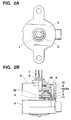
- Figs. 2A and 2B are a plan view and a partially cutaway side view, respectively, showing the structure of a planetary gear reduction device with a torque limiter function according to the first embodiment of the present invention.
- a stationary ring gear 6 is fixedly attached to a lower portion of a housing 3, and a motor 5 is mounted on a lower side of the ring gear 6.
- a sun gear 4 is fixedly mounted to an output shaft 5a of the motor 5 which is rotatably supported by the housing 3 and located at a radially central and axially lower portion of the housing 3.
- the motor output shaft 5a serves as an input shaft of the planetary gear reduction device with the torque limiter function.
- a planetary gear 7 meshes with the sun gear 4 through respective teeth formed on their respective outer circumferential surfaces, and with the ring gear 6 through inner teeth formed on an inner circumferential surface of the ring gear 6.
- the planetary gear 7 is coaxially, integrally overlaid with a planetary bevel gear 8.
- a plurality of planetary gear pairs each of which is integrally constituted by the planetary gear 7 and the planetary bevel gear 8 and rotatably attached through an attaching shaft to a carrier 11 provided under the planetary gear 7 and a carrier 12 provided above the planetary bevel gear 8, are provided around the sun gear 4.
- Fig. 2B shows one planetary gear pair.
- An output shaft 1 is rotatably supported by the housing 3, axially fixed by means of a stop ring 2 mounted to the housing 3, and located at a radially central and axially upper portion of the housing 3.
- a flange gear 9 is mounted to the output shaft 1 freely in the axial direction and fixedly in the circumferential direction and meshes with the planetary bevel gear 8 such that inner teeth 9a formed on a bevelled lower end surface of the flange gear 9 engage with teeth 8a formed on an outer surface of the planetary bevel gear 8 (although not shown, the flange gear 9 similarly meshes with other planetary bevel gears 8 at different positions).
- a portion of the output shaft 1, to which the flange gear 9 is attached, is processed with a D-cut or a spline, so the flange gear 9 can freely move in the axial direction while it is immovable in the rotational direction.
- a compression spring 10 for constantly pressing the flange gear 9 toward the planetary bevel gear 8 is interposed between an upper surface of the flange gear 9 and a lower surface of an upper lid of the housing 3. If the compression spring 10 is a conical spring, it can press the flange gear 9 with a good balance and can decrease the compression height, thus enabling downsizing.
- the planetary gear reduction device with the torque limiter function reduces the rotation speed of the motor 5.
- a reaction force generated between the teeth 8a of the planetary bevel gear 8 and the inner teeth 9a of the flange gear 9 increases.
- the flange gear 9 moves upward against the pressing force of the compression spring 10 to disengage from the planetary bevel gear 8.
- torque transmission is disconnected between the flange gear 9 and the planetary bevel gear 8.
- the planetary gear reduction device with the torque limiter function according to the first embodiment can have a built-in torque limiting mechanism constituted of the planetary bevel gear 8, the flange gear 9, and the compression spring 10, so that it can be made simple in structure and compact while obtaining a large reduction ratio and assuring safety.
- the torque can be transmitted smoothly, and noise as the disadvantage of the planetary gear reduction device can be decreased.
- Figs. 3A and 3B are a plan view and a partially cutaway side view, respectively, showing the structure of a planetary gear reduction device with a torque limiter function according to the second embodiment of the present invention.
- a stationary ring gear 26 is fixedly attached to a lower portion of a housing 23, and a motor 25 is mounted on a lower side of the ring gear 26.
- a sun gear 24 is fixedly mounted to an output shaft 25a of the motor 25 which is rotatably supported by the housing 23 and located at a radially central and axially lower portion of the housing 23.
- the motor output shaft 25a serves as an input shaft of the planetary gear reduction device with the torque limiter function.
- a first planetary gear 27 meshes with the sun gear 24 through respective teeth formed on their respective outer surfaces, and meshes with the ring gear 26 through inner teeth formed on an inner circumferential surface of the ring gear 26.
- the first planetary gear 27 is coaxially, integrally overlaid with a second planetary gear 28.
- a plurality of planetary gear pairs each of which is integrally constituted by the first and second planetary gears 27 and 28 and rotatably mounted through a mounting shaft to a carrier 32 provided under the first planetary gear 27 and a carrier 33 provided above the second planetary gear 28, are provided around the sun gear 24.
- Fig. 3B shows one planetary gear pair.
- An output shaft 21 is rotatably supported by the housing 23, axially fixed by means of a stop ring 22 mounted to the housing 23, and located at a radially central and axially upper portion of the housing 23.
- a flange gear 29 is mounted to the output shaft 21 fixedly in the axial direction and freely in the circumferential direction and meshes with the second planetary gear 28 such that inner teeth 29a formed on a lower inner circumferential surface of the flange gear 29 engage with teeth 28a formed on an outer circumferential surface of the second planetary gear 28 (although not shown, the flange gear 29 similarly meshes with other planetary gears 28 at different positions).
- a compression spring 30 for constantly pressing the declutch gear 31 toward the flange gear 29 is interposed between an upper surface of the declutch gear 31 and a lower surface of an upper lid of the housing 23. If the compression spring 30 is a conical spring in the same manner as the compression spring 10 of the first embodiment, it can press the declutch gear 31 with a good balance and can reduce the dimension simultaneously.
- the sun gear 24 and the first planetary gear 27 are rotated. Since the first planetary gear 27 meshes with the ring gear 26 which is stationary, it moves around the sun gear 24 while rotating, thereby rotating the flange gear 29 through the second planetary gear 28. Successively, the flange gear 29 meshes with the declutch gear 31, so rotation speed of the motor output shaft 25a is reduced to that of the output shaft 21.
- a reaction force generated between the bevel teeth 29b formed on the upper surface of the flange gear 29 and the bevel teeth 31a of the declutch gear 31 increases, whereby the declutch gear 31 moves upward against the pressing force of the compression spring 30 to disengage from the flange gear 29 disconnecting torque transmission between the declutch gear 31 and the flange gear 29.
- the planetary gear reduction device with the torque limiter function according to the second embodiment can effect the torque limiter function by means of the bevel teeth 29b formed on the flange gear 29, the declutch gear 31, and the compression spring 30, it can be made simple in structure and compact while obtaining a large reduction ratio and assuring safety.
- the torque can be transmitted smoothly, and noise as the disadvantage of the planetary gear reduction device can be decreased.
- the torque limiting mechanism in place of the bevel teeth 29b of the upper surface of the flange gear 29 and the bevel teeth 31a of the declutch gear 31, the torque limiting mechanism may be formed, as shown in Fig. 4, of a friction surface portion 59b formed on an upper surface of a flange gear 59, and a clutch disk 61 mounted to an output shaft 41 freely in the axial direction and fixedly in the rotational direction and adapted to come in frictional contact with the friction surface portion 59b normally.
Landscapes
- Engineering & Computer Science (AREA)
- General Engineering & Computer Science (AREA)
- Mechanical Engineering (AREA)
- Transmission Devices (AREA)
- Retarders (AREA)
Abstract
Description
Claims (20)
- A planetary gear reduction device with a torque limiter function, comprising:whereby when an excessive torque is generated in said output shaft, torque transmission from said input shaft to said output shaft is disconnected by an action of said torque limiting mechanism.(a) a housing;(b) an input shaft commonly served by an output shaft of a power source, rotatably supported by one of end of said housing, located at a radially central and axially lower portion of said housing and adapted to take in a torque from the power source;(c) an output shaft rotatably supported by the othe end of said housing, located at a radially central and axially upper portion of said housing adapted to take out the torque transmitted from the power source;(d) a reduction gear train provided between said input shaft and said output shaft and comprising a plurality of gears meshing with one another; and(e) a built-in torque limiting mechanism constituted in said reduction gear train,
- A device according to claim 1,
wherein said torque limiting mechanism comprises:whereby when an excessive torque is generated in said output shaft, said planetary bevel gear and said flange gear are disengaged from each other by a reaction force generated between respective teeth of those gears meshing with each other so as to disconnect torque transmission from said input shaft to said output shaft.a planetary bevel gear which is one gear of said reduction gear train;a flange gear mounted to said output shaft freely in an axial direction and fixedly in a circumferential direction and meshing with said planetary bevel gear through inner teeth formed on a bevelled lower end surface thereof;a compression means provided between an upper surface of said flange gear and a lower surface of an upper lid of said housing and adapted to constantly press said flange gear toward said planetary bevel gear, - A device according to claim 1,
wherein said torque limiting mechanism comprises:whereby when an excessive torque is generated in said output shaft, said declutch gear and said internal gear are disengaged from each other by a reaction force generated between respective teeth of those gears meshing with each other so as to disconnect torque transmission from said input shaft to said output shaft.a flange gear mounted to said output shaft fixedly in an axial direction and freely in a circumferential direction;an internal gear formed on an upper surface of said flange gear;a declutch gear mounted to said output shaft freely in the axial direction and fixedly in the circumferential direction and adapted to mesh with said internal gear; anda compression means provided between an upper surface of said declutch gear and a lower surface of an upper lid of said housing and adapted to constantly press said declutch gear toward said internal gear, - A device according to claim 1,
wherein said torque limiting mechanism comprises:whereby when an excessive torque is generated in said output shaft, said clutch disk and said friction surface portion are disengaged from each other by a reaction force generated therebetween so as to disconnect torque transmission from said input shaft to said output shaft.a flange gear mounted to said output shaft fixedly in an axial direction and freely in a circumferential direction;a friction surface portion formed on an upper surface of said flange gear;a clutch disk mounted to the output shaft freely in the axial direction and fixedly in the circumferential direction and adapted to come in frictional contact with said friction surface portion; anda compression means provided between an upper surface of said clutch disk and a lower surface of an upper lid of said housing and adapted to constantly press said clutch disk toward said friction surface portion, - A device according to claim 1, wherein some of gears of said reduction gear train are helical gears.
- A device according to claim 2, wherein said compression means is a conical compression spring.
- A device according to claim 3, wherein said compression means is a conical compression spring.
- A device according to claim 4, wherein said compression means is a conical compression spring.
- A planetary gear reduction device with a torque limiter function, comprising:whereby when an excessive torque is generated in the output shaft, said flange gear and said planetary bevel gear are disengaged from each other by a reaction force generated between respective teeth of those gears meshing with each other so as to disconnect torque transmission therebetween.a sun gear fixedly mounted to an input shaft rotatably supported and located at a radially central and axially lower portion of a housing;at least one planetary gear meshing with said sun gear through respective teeth formed on their respective outer circumferential surfaces;a stationary ring gear having inner teeth and meshing with said planetary gear through the inner teeth thereof;at least one planetary bevel gear coaxially and integrally mounted on said planetary gear to constitute at least one planetary gear pair;an output shaft rotatably supported and located at a radially central and axially upper portion of said housing;a flange gear mounted to said output shaft freely in an axial direction and fixedly in a circumferential direction and meshing with said planetary bevel gear through inner teeth formed on a bevelled lower end surface thereof; and .means provided between an upper surface of said flange gear and a lower surface of an upper lid of said housing and adapted to constantly press said flange gear toward said planetary bevel gear,
- A planetary gear reduction device with a torque limiter function, comprising:whereby when an excessive torque is generated in said output shaft, said declutch gear and said internal gear are disengaged from each other by a reaction force generated between respective teeth of those gears meshing with each other so as to disconnect torque transmission therebetween.a sun gear fixedly mounted to an input shaft rotatably supported and located at a radially central and axially lower portion of a housing;at least one first planetary gear meshing with said sun gear through respective teeth formed on their respective outer circumferential surfaces;a stationary ring gear having inner teeth and meshing with said first planetary gear through the inner teeth thereof;at least one second planetary gear coaxially and integrally mounted on said first planetary gear to constitute at least one planetary gear pair;an output shaft rotatably supported and located at a radially central and axially upper portion of said housing;a flange gear mounted to said output shaft fixedly in an axial direction and freely in a circumferential direction and meshing with said second planetary gear through inner teeth formed on a lower portion of an inner circumferential surface thereof;an internal gear formed on an upper surface of said flange gear;a declutch gear mounted to said output shaft freely in the axial direction and fixedly in the circumferential direction and adapted to mesh with said internal gear; andmeans provided between an upper surface of said declutch gear and a lower surface of an upper lid of said housing and adapted to constantly press said declutch gear toward said internal gear,
- A planetary gear reduction device with a torque limiter function, comprising:whereby when an excessive torque is generated in said output shaft, said clutch disk and said friction surface portion that are in frictional contact are disengaged from each other by a reaction force generated therebetween so as to disconnect torque transmission therebetween.a sun gear fixedly mounted to an input shaft rotatably supported and located at a radially central and axially lower portion of a housing;at least one first planetary gear meshing with said sun gear through respective teeth formed on their respective outer circumferential surfaces;a stationary ring gear having inner teeth and meshing with said first planetary gear through the inner teeth thereof;at least one second planetary gear coaxially and integrally mounted on said first planetary gear to constitute at least one planetary gear pair;an output shaft rotatably supported and located at a radially central and axially upper portion of said housing;a flange gear mounted to said output shaft fixedly in an axial direction and freely in a circumferential direction and meshing with said second planetary gear through inner teeth formed on a lower portion of an inner circumferential surface thereof;a friction surface portion formed on an upper surface of said flange gear;a clutch disk mounted to said output shaft freely in the axial direction and fixedly in the circumferential direction and adapted to come in frictional contact with said friction surface portion; andmeans provided between an upper surface of said clutch disk and a lower surface of an upper lid of said housing and adapted to constantly press said clutch disk toward said friction surface portion,
- A device according to claim 9, wherein said sun gear, said planetary gear, and said ring gear are helical gears.
- A device according to claim 10, wherein said sun gear, said first planetary gear, and said ring gear are helical gears.
- A device according to claim 11, wherein said sun gear, said first planetary gear, and said ring gear are helical gears.
- A device according to claim 9, wherein said means for pressing is a conical compression spring.
- A device according to claim 10, wherein said means for pressing is a conical compression spring.
- A device according to claim 11, wherein said means for pressing is a conical compression spring.
- A device according to claim 9, wherein a plurality of planetary gear pairs are provided along an inner circumferential surface of said ring gear.
- A device according to claim 10, wherein a plurality of planetary gear pairs are provided along an inner circumferential surface of said ring gear.
- A device according to claim 11, wherein a plurality of planetary gear pairs are provided along an inner circumferential surface of said ring gear.
Priority Applications (1)
| Application Number | Priority Date | Filing Date | Title |
|---|---|---|---|
| EP06013909A EP1722128A1 (en) | 2000-12-04 | 2001-12-03 | Planetary gear reduction device with torque limiter function |
Applications Claiming Priority (2)
| Application Number | Priority Date | Filing Date | Title |
|---|---|---|---|
| JP2000368254A JP4800474B2 (en) | 2000-12-04 | 2000-12-04 | Planetary gear reducer with torque limiter function |
| JP2000368254 | 2000-12-04 |
Related Child Applications (1)
| Application Number | Title | Priority Date | Filing Date |
|---|---|---|---|
| EP06013909A Division EP1722128A1 (en) | 2000-12-04 | 2001-12-03 | Planetary gear reduction device with torque limiter function |
Publications (3)
| Publication Number | Publication Date |
|---|---|
| EP1211435A2 true EP1211435A2 (en) | 2002-06-05 |
| EP1211435A3 EP1211435A3 (en) | 2004-09-29 |
| EP1211435B1 EP1211435B1 (en) | 2008-06-04 |
Family
ID=18838540
Family Applications (2)
| Application Number | Title | Priority Date | Filing Date |
|---|---|---|---|
| EP06013909A Withdrawn EP1722128A1 (en) | 2000-12-04 | 2001-12-03 | Planetary gear reduction device with torque limiter function |
| EP01310096A Expired - Lifetime EP1211435B1 (en) | 2000-12-04 | 2001-12-03 | Planetary gear reduction device with torque limiter function |
Family Applications Before (1)
| Application Number | Title | Priority Date | Filing Date |
|---|---|---|---|
| EP06013909A Withdrawn EP1722128A1 (en) | 2000-12-04 | 2001-12-03 | Planetary gear reduction device with torque limiter function |
Country Status (4)
| Country | Link |
|---|---|
| US (2) | US6682454B2 (en) |
| EP (2) | EP1722128A1 (en) |
| JP (1) | JP4800474B2 (en) |
| DE (1) | DE60134303D1 (en) |
Cited By (3)
| Publication number | Priority date | Publication date | Assignee | Title |
|---|---|---|---|---|
| EP1775465A3 (en) * | 2005-10-13 | 2012-10-31 | General Electric Company | Device for driving a first part of a wind energy turbine with respect to a second part of the wind energy turbine |
| CN103939587A (en) * | 2013-01-23 | 2014-07-23 | 博世汽车部件(长沙)有限公司 | Vehicle starter and overload protection and vibration reduction device thereof |
| CN112572781A (en) * | 2020-12-04 | 2021-03-30 | 中国航空工业集团公司成都飞机设计研究所 | Front wheel turning speed reduction output mechanism |
Families Citing this family (15)
| Publication number | Priority date | Publication date | Assignee | Title |
|---|---|---|---|---|
| SE526995C2 (en) * | 2003-10-03 | 2005-12-06 | Atlas Copco Tools Ab | Power tool with planetary reduction gear |
| JP4986841B2 (en) * | 2004-02-24 | 2012-07-25 | リナック エー/エス | Linear actuator |
| WO2006047892A1 (en) * | 2004-11-08 | 2006-05-11 | Tesco Corporation | Wellbore tubular handling torque multiplier |
| JP2008261504A (en) * | 2008-07-23 | 2008-10-30 | Enplas Corp | Clutch mechanism and robot hand finger drive mechanism |
| JP2010164064A (en) * | 2009-01-13 | 2010-07-29 | Apex Dynamics Inc | Low back surface gap precision planetary type gear reducer |
| US9303733B2 (en) | 2009-07-20 | 2016-04-05 | Differential Dynamics Corporation | Three variable and four variable transgear assemblies |
| US9476401B2 (en) * | 2010-07-20 | 2016-10-25 | Differential Dynamics Corporation | Marine hydrokinetic turbine |
| US9490736B2 (en) * | 2010-07-20 | 2016-11-08 | Differential Dynamics Corporation | Adjustable assembly of rotor and stator and applications thereof with a variable power generator |
| CN102278448A (en) * | 2011-05-30 | 2011-12-14 | 长沙星轮传动设备有限公司 | Full hanging star wheel flexible gearing |
| EP2602504B1 (en) * | 2011-12-09 | 2014-05-21 | Robert Bosch GmbH | Planetary or epicyclic gear assembly with protection clutch |
| WO2015160623A1 (en) * | 2014-04-17 | 2015-10-22 | Differential Dynamics Corporation | Three, four, five and n variable transgear assemblies |
| DE102016123613B4 (en) | 2016-12-06 | 2021-02-04 | Deutsches Zentrum für Luft- und Raumfahrt e.V. | Gearbox with overload clutch |
| CN109838528B (en) * | 2019-03-29 | 2021-12-03 | 伊蒙妮莎(常州)发电设备有限公司 | Bidirectional clutch torque limiting release for diesel generator |
| EP4103009A4 (en) * | 2020-02-14 | 2024-03-13 | Shift Holding, LLC | SHIFT DRUM AND ASSOCIATED METHODS |
| CN114753824B (en) * | 2021-01-08 | 2024-05-28 | 中国石油天然气股份有限公司 | A continuously variable speed drilling tool with adaptive torque |
Family Cites Families (16)
| Publication number | Priority date | Publication date | Assignee | Title |
|---|---|---|---|---|
| US1318568A (en) * | 1919-10-14 | Hoist | ||
| US2764272A (en) * | 1954-03-30 | 1956-09-25 | Ingersoll Rand Co | Overload release for torque wrench |
| JPS5787833U (en) * | 1980-11-18 | 1982-05-31 | ||
| JPS588850A (en) * | 1981-07-07 | 1983-01-19 | Iseki & Co Ltd | Safety device in reduction gear |
| JPS58138852U (en) * | 1982-03-15 | 1983-09-19 | 株式会社クボタ | Agricultural bevel gear transmission |
| GB8314793D0 (en) * | 1983-05-27 | 1983-07-06 | Lucas Ind Plc | Starter motors |
| US4555963A (en) * | 1983-11-17 | 1985-12-03 | Wedgtrac Corporation | Torque limit drive transmission |
| JPH0823948B2 (en) * | 1993-06-28 | 1996-03-06 | ヤマウチ株式会社 | Magnetic torque limiter and reel stand device |
| US5596548A (en) * | 1994-05-12 | 1997-01-21 | Exxon Production Research Company | Seismic imaging using wave equation extrapolation |
| DE19525831A1 (en) * | 1995-07-15 | 1997-01-16 | Zahnradfabrik Friedrichshafen | Planetary gear |
| NL1001412C2 (en) * | 1995-10-12 | 1997-04-15 | Iku Holding Montfoort Bv | Drive unit with adjustable torque. |
| JPH09119503A (en) * | 1995-10-25 | 1997-05-06 | East Japan Railway Co | Planetary gear reducer with torque limiter |
| SE9600933D0 (en) * | 1996-03-11 | 1996-03-11 | Atlas Copco Tools Ab | Power nutrunner |
| US5713813A (en) * | 1996-07-18 | 1998-02-03 | Von Greyerz; John W. | Trans-planetary mechanical torque impeller |
| JPH11346469A (en) * | 1998-05-29 | 1999-12-14 | Minebea Co Ltd | Stepping motor with speed change mechanism |
| US6519532B2 (en) * | 2001-01-31 | 2003-02-11 | Phillips Petroleum Company | Method and apparatus for 3D depth migration |
-
2000
- 2000-12-04 JP JP2000368254A patent/JP4800474B2/en not_active Expired - Fee Related
-
2001
- 2001-11-29 US US09/997,793 patent/US6682454B2/en not_active Expired - Fee Related
- 2001-12-03 DE DE60134303T patent/DE60134303D1/en not_active Expired - Lifetime
- 2001-12-03 EP EP06013909A patent/EP1722128A1/en not_active Withdrawn
- 2001-12-03 EP EP01310096A patent/EP1211435B1/en not_active Expired - Lifetime
-
2003
- 2003-09-24 US US10/669,218 patent/US6824490B2/en not_active Expired - Lifetime
Cited By (4)
| Publication number | Priority date | Publication date | Assignee | Title |
|---|---|---|---|---|
| EP1775465A3 (en) * | 2005-10-13 | 2012-10-31 | General Electric Company | Device for driving a first part of a wind energy turbine with respect to a second part of the wind energy turbine |
| CN103939587A (en) * | 2013-01-23 | 2014-07-23 | 博世汽车部件(长沙)有限公司 | Vehicle starter and overload protection and vibration reduction device thereof |
| CN103939587B (en) * | 2013-01-23 | 2017-06-23 | 博世汽车部件(长沙)有限公司 | Vehicle starter and its overload protection and vibration absorber |
| CN112572781A (en) * | 2020-12-04 | 2021-03-30 | 中国航空工业集团公司成都飞机设计研究所 | Front wheel turning speed reduction output mechanism |
Also Published As
| Publication number | Publication date |
|---|---|
| JP2002174304A (en) | 2002-06-21 |
| DE60134303D1 (en) | 2008-07-17 |
| EP1211435A3 (en) | 2004-09-29 |
| EP1211435B1 (en) | 2008-06-04 |
| EP1722128A1 (en) | 2006-11-15 |
| US6682454B2 (en) | 2004-01-27 |
| US6824490B2 (en) | 2004-11-30 |
| US20040058777A1 (en) | 2004-03-25 |
| JP4800474B2 (en) | 2011-10-26 |
| US20020068658A1 (en) | 2002-06-06 |
Similar Documents
| Publication | Publication Date | Title |
|---|---|---|
| US6824490B2 (en) | Planetary gear reduction device with torque limiter function | |
| US4189960A (en) | Underdrive transmission with sun gear and carrier slidable as a subassembly | |
| EP0302229A3 (en) | Rotary electric tool with a variable speed gearing | |
| JPS627419B2 (en) | ||
| CN107165956B (en) | Clearance control swash plate device and single-shaft two-speed driving system using friction clutch | |
| EP0620383A2 (en) | Centrifugal planetary friction transmission | |
| EP0058834B1 (en) | A continuously variable transmission for motor vehicles | |
| US3182525A (en) | Power actuator with harmonic drive | |
| US4949587A (en) | Reverse gear mechanism for vehicle gear transmission | |
| US5501636A (en) | Rotary machine system having hollow tube shaft and plural output shafts | |
| EP0172286B1 (en) | Transmission for use in motor vehicle | |
| US5184807A (en) | Electric hoist including a planetary reduction gear housing disposed within a hoist drum | |
| US12372153B2 (en) | Self-locking mechanism for gearing arrangement, gearing arrangement, actuator, and lifting platform | |
| EP2458247B1 (en) | Basic gearbox and range gearbox for motor vehicle | |
| JPH0134542Y2 (en) | ||
| JP2907642B2 (en) | Belt-type continuously variable transmission | |
| CN221958073U (en) | Gearbox and electric engineering machinery | |
| JPH0631239Y2 (en) | Speed change mechanism | |
| JPH07190085A (en) | Transaxle of self-propelled traveling work vehicle | |
| JP3161260B2 (en) | Gear transmission | |
| JP2504469Y2 (en) | Two-speed switching gear device | |
| JPS6120744B2 (en) | ||
| JPH0649958Y2 (en) | Sliding mesh type gear mechanism | |
| JPH0713926Y2 (en) | Power tool speed switching mechanism | |
| KR200198471Y1 (en) | Steering device of manager |
Legal Events
| Date | Code | Title | Description |
|---|---|---|---|
| PUAI | Public reference made under article 153(3) epc to a published international application that has entered the european phase |
Free format text: ORIGINAL CODE: 0009012 |
|
| AK | Designated contracting states |
Kind code of ref document: A2 Designated state(s): AT BE CH CY DE DK ES FI FR GB GR IE IT LI LU MC NL PT SE TR |
|
| AX | Request for extension of the european patent |
Free format text: AL;LT;LV;MK;RO;SI |
|
| PUAL | Search report despatched |
Free format text: ORIGINAL CODE: 0009013 |
|
| RIC1 | Information provided on ipc code assigned before grant |
Ipc: 7F 16H 35/10 A |
|
| AK | Designated contracting states |
Kind code of ref document: A3 Designated state(s): AT BE CH CY DE DK ES FI FR GB GR IE IT LI LU MC NL PT SE TR |
|
| AX | Request for extension of the european patent |
Extension state: AL LT LV MK RO SI |
|
| 17P | Request for examination filed |
Effective date: 20041020 |
|
| AKX | Designation fees paid |
Designated state(s): DE FR IT |
|
| GRAP | Despatch of communication of intention to grant a patent |
Free format text: ORIGINAL CODE: EPIDOSNIGR1 |
|
| GRAS | Grant fee paid |
Free format text: ORIGINAL CODE: EPIDOSNIGR3 |
|
| GRAA | (expected) grant |
Free format text: ORIGINAL CODE: 0009210 |
|
| AK | Designated contracting states |
Kind code of ref document: B1 Designated state(s): DE FR IT |
|
| REF | Corresponds to: |
Ref document number: 60134303 Country of ref document: DE Date of ref document: 20080717 Kind code of ref document: P |
|
| PLBE | No opposition filed within time limit |
Free format text: ORIGINAL CODE: 0009261 |
|
| STAA | Information on the status of an ep patent application or granted ep patent |
Free format text: STATUS: NO OPPOSITION FILED WITHIN TIME LIMIT |
|
| PGFP | Annual fee paid to national office [announced via postgrant information from national office to epo] |
Ref country code: FR Payment date: 20081212 Year of fee payment: 8 |
|
| 26N | No opposition filed |
Effective date: 20090305 |
|
| PG25 | Lapsed in a contracting state [announced via postgrant information from national office to epo] |
Ref country code: IT Free format text: LAPSE BECAUSE OF FAILURE TO SUBMIT A TRANSLATION OF THE DESCRIPTION OR TO PAY THE FEE WITHIN THE PRESCRIBED TIME-LIMIT Effective date: 20080604 |
|
| REG | Reference to a national code |
Ref country code: FR Ref legal event code: ST Effective date: 20100831 |
|
| PG25 | Lapsed in a contracting state [announced via postgrant information from national office to epo] |
Ref country code: FR Free format text: LAPSE BECAUSE OF NON-PAYMENT OF DUE FEES Effective date: 20091231 |
|
| PGFP | Annual fee paid to national office [announced via postgrant information from national office to epo] |
Ref country code: DE Payment date: 20141125 Year of fee payment: 14 |
|
| REG | Reference to a national code |
Ref country code: DE Ref legal event code: R119 Ref document number: 60134303 Country of ref document: DE |
|
| PG25 | Lapsed in a contracting state [announced via postgrant information from national office to epo] |
Ref country code: DE Free format text: LAPSE BECAUSE OF NON-PAYMENT OF DUE FEES Effective date: 20160701 |