EP1211026B1 - Rolling and roller tools, roller constructions and roller equipment - Google Patents
Rolling and roller tools, roller constructions and roller equipment Download PDFInfo
- Publication number
- EP1211026B1 EP1211026B1 EP01308252A EP01308252A EP1211026B1 EP 1211026 B1 EP1211026 B1 EP 1211026B1 EP 01308252 A EP01308252 A EP 01308252A EP 01308252 A EP01308252 A EP 01308252A EP 1211026 B1 EP1211026 B1 EP 1211026B1
- Authority
- EP
- European Patent Office
- Prior art keywords
- roller
- annular
- rolling
- workpiece
- shoulders
- Prior art date
- Legal status (The legal status is an assumption and is not a legal conclusion. Google has not performed a legal analysis and makes no representation as to the accuracy of the status listed.)
- Expired - Lifetime
Links
Images


Classifications
-
- F—MECHANICAL ENGINEERING; LIGHTING; HEATING; WEAPONS; BLASTING
- F16—ENGINEERING ELEMENTS AND UNITS; GENERAL MEASURES FOR PRODUCING AND MAINTAINING EFFECTIVE FUNCTIONING OF MACHINES OR INSTALLATIONS; THERMAL INSULATION IN GENERAL
- F16C—SHAFTS; FLEXIBLE SHAFTS; ELEMENTS OR CRANKSHAFT MECHANISMS; ROTARY BODIES OTHER THAN GEARING ELEMENTS; BEARINGS
- F16C3/00—Shafts; Axles; Cranks; Eccentrics
- F16C3/04—Crankshafts, eccentric-shafts; Cranks, eccentrics
- F16C3/06—Crankshafts
- F16C3/08—Crankshafts made in one piece
-
- B—PERFORMING OPERATIONS; TRANSPORTING
- B24—GRINDING; POLISHING
- B24B—MACHINES, DEVICES, OR PROCESSES FOR GRINDING OR POLISHING; DRESSING OR CONDITIONING OF ABRADING SURFACES; FEEDING OF GRINDING, POLISHING, OR LAPPING AGENTS
- B24B39/00—Burnishing machines or devices, i.e. requiring pressure members for compacting the surface zone; Accessories therefor
- B24B39/04—Burnishing machines or devices, i.e. requiring pressure members for compacting the surface zone; Accessories therefor designed for working external surfaces of revolution
- B24B39/045—Burnishing machines or devices, i.e. requiring pressure members for compacting the surface zone; Accessories therefor designed for working external surfaces of revolution the working tool being composed of a plurality of working rolls or balls
-
- B—PERFORMING OPERATIONS; TRANSPORTING
- B24—GRINDING; POLISHING
- B24B—MACHINES, DEVICES, OR PROCESSES FOR GRINDING OR POLISHING; DRESSING OR CONDITIONING OF ABRADING SURFACES; FEEDING OF GRINDING, POLISHING, OR LAPPING AGENTS
- B24B5/00—Machines or devices designed for grinding surfaces of revolution on work, including those which also grind adjacent plane surfaces; Accessories therefor
- B24B5/36—Single-purpose machines or devices
- B24B5/42—Single-purpose machines or devices for grinding crankshafts or crankpins
Definitions
- the present invention relates to a rolling tool, as per the preamble of claim 1.
- a rolling tool as per the preamble of claim 1.
- An example of such a tool is disclosed by US 5 445 003 A .
- the fillet rollers experience high loads and mechanical wear from the back up rollers of the deep rolling machine. More particularly the back up roller imparts the large rolling loads directly onto the circumferential rolling edge of the fillet rollers as the crankshaft is turned in the machine and the fillet rollers impart deep compressive stresses in the fillets. Deep rolling tools of this type are shown in United States patent 5,445,003 (Hegenborgt Corporation). The large loads directed onto small contact areas of the rolling edge of the fillet rollers by the back up roller effect fillet roller wear which materially reduces the service life of the fillet rollers and productivity of fillet rolling equipment.
- This invention effectively increases the contact area between the back up roller and the workpiece or fillet roller so that the fillet roller loading is spread and fillet roller wear is resultantly reduced and tool life of the fillet roller is increased. More particularly by dividing the back up roller load so that it is directed to opposite sides of the annular working edge of the fillet roller, the rolling edge thereof experiences reduced wear so that fillet rollers, and deep rolling equipment life is increased. With this invention the rolling loads directed by the back up roller to the fillet rollers are on opposite sides of the rolling edge of the fillet roller so that fillet roller stability is improved during the deep rolling cycle.
- This invention is particularly useful in increasing service life on a wide range of workpiece rollers and including those having a compound rolling radius to effect the optimized deep rolling of pin journals having undercuts with compound radii to increase the effective width of such journals.
- FIGS. 1 and 2 diagrammatically show portions of a metal working machine 10 illustrating some principals of deep roll strengthening of the fillets of crank pins 12 and main journals of a crankshaft 14 for an internal combustion engine.
- the crankshaft has a nose end 16 mounted in a chuck 18 and a flange end supported by a dead point center 22 of the machine.
- the crankshaft can be selectively and rotatably driven about horizontal axis B by a drive motor 24 supported by a mounting collar 26 on the machine housing and drivingly connected to the chuck by drive shaft 28.
- Each of the crank pins 12 is defined by side-by-side and coaxial journal portions 30 and 32 ( FIG. 3 ) providing cylindrical bearings for the connecting rods 34, 36 ( FIG. 4 ) of opposing pistons in the left and right cylinders of V-block engines.
- pin journal portions 30, 32 experience high stress loads during engine operation, they are strengthened in various ways such as by deep roll hardening of their laterally spaced annular fillets F, F' in which high and concentrated rolling forces are directed to the undercuts or annular fillets areas of the crankshaft.
- Such rolling produces compressive strengthening stresses in the metal of the crankshaft fillets that may, for example, extend to a depth of 4 mm.
- the upper tool 40 has a rotatable and generally cylindrical back up roller R having annular tracks T, T' operatively engaging a pair of floating workpiece rollers 46, 46' of hardened steel or other suitable material.
- the back up roller is rotatably mounted in the housing by suitable bearing such as disclosed in U.S. Patent No. 5,445,003 issued August 29, 1995 assigned to the assignee of this invention and hereby incorporated by reference.
- the workpiece rollers are operatively mounted in a cage C carried by the upper tool and generally turn on oppositely inclined axes A and A' to engage and deep roll the annular and laterally spaced undercuts or fillets F, F' providing the annular joint areas of the crankshaft journals such as the fillets, between the pins and the adjacent counter weights or bearing collars of the crankshaft.
- the annular working edge sections E of the rollers 46, 46' are designed to fit into the journal fillet F, F' and, for adequate penetration, the radius of the roller edge has generally been formed with a 180-degree arc.
- the actual size of the roller edge radius should be designed to lie within the machining tolerance for the crankshaft fillet.
- the lower tool 41 has radially spaced support rollers 47 that provide the bearing and support for the crank pins as the crankshaft 14 is being rotatably driven about its axis B and the fillets F, F' are being deep rolled.
- Rolling pressure is hydraulically applied by the expansion force of a hydraulic cylinder 48 operatively connected between the extending ends 49,50 of the upper and lower jaw arms 51, 52 pivoted together by a clevis mounted pivot 53 disposed at an intermediate position along the jaw arm lengths.
- This arrangement provides the mechanical advantage that amplifies the jaw closure force exerted to the jaw assembly by the expansion force of the hydraulic power cylinder 48.
- the flexible support 45 By virtue of the flexible support 45, the upper and lower jaws and their tools are supported to float around the axis of the orbiting crank pins during rolling.
- Rolling pressure, transmitted by the back up roller R, and exerted by the rollers 46, 46' can be increased and decreased by means of cylinder 48 during rotational drive of the crankshaft by motor 24 to impart concentrated annular residual stress patterns in the metal of the fillets F, F' which are among the most highly stressed cross-sectional areas of the crankshaft in engine operation.
- the amount of pressure as well as the number of over rolls of the fillets can be preselected to produce optimized fatigue strength.
- crank pin journals such as width W of pin journal 12 defined by side-by-side cylindrical journal portions 30,32 of FIG. 3 .
- a limited increase in effective width is needed.
- work rollers with smaller and compound rolling radii of the annular working edge have been utilized to deep roll the annular undercuts machined with corresponding smaller annular radii.
- the desired increase in width of the journal is obtained.
- the rolling force F from cylinder 48 is applied directly to the annular working edge of the working roller by the back up roller R.
- This force is further transmitted by the working roller into the annular fillet F-I which is cold worked and compressively stressed to increase fatigue life of the journal through the diameter of the work roller and the smaller roller edge.
- Such highly concentrated work loads particularly those imparted to the smaller radiused working edge of the Figure 5b work roller by the back up roller R, result in proportionally increased wear of the work rollers and sharply reduced work life thereof as discussed above.
- roller life is within the range of 200 -500 pieces (2000 pieces at most) as compared to the regular standard of 5,000 pieces. This reduced roller work life is generally not acceptable for high volume production so new and improved tooling is needed.
- FIGS 6 and 7 illustrates one preferred embodiment of the present invention.
- the annular working edges 100 and 100' of work rollers 102 and 102' respectively have small working radii, r' which may be 1.68mm and equal to the small working radius of the annular working edge of the work roller of Fig. 5b to provide the desired increase in width of the pin journal as discussed above.
- the work life of work roller 102, 102' is materially increased by providing annular shoulders 104, 106 and 104' and 106' on opposite sides of the annular roller edges 100 and 100'.
- the back up roller 110 has annular grooves or tracks 112 and 114 therein which receive with clearance the annular working edges 100 and 100' of the associated working rollers.
- the load or rolling force F from the cylinder 48 is split by the annular contact shoulders 116, 118 and 116' and 118' of the back up roller 110 which respectively and rollingly contact the annular side shoulders 104, 106 and 104' and 106' of the two working rollers.
- the rolling loads are not directed onto the annular working edges of the workpiece rollers but are imparted to the shoulders on either side thereof.
- This division and spread of load F applied to the working rollers by the back-up roller there is materially increased working life of the back-up roller and more particularly of each of the workpiece roller 102, 102' in rolling fillets 120, 120'.
- This construction resultantly meets productivity requirements and can reach or exceed 5000 pieces.
- the fillets 120, 120' are formed between the journal and an adjacent counterweight (105, 105').
- FIGS. 8 and 9 are views of another preferred embodiment of the present invention with the annular working edges 200 and 200' of work rollers 202 and 202' formed with variable radii.
- the back up roller 204 has annular grooves or tracks 206, 206' to receive with clearance the annular working edges 200, 200' of the working roller, the back-up roller is formed with spaced annular contact shoulders 208, 210 and 208' and 210' with inner annular contact surfaces to physically engage the hub-like annular contact shoulders 212, 214, 212', 214' formed on either side of the annular working edges 200, 200' of the working rollers.
- FIG. 10 illustrates the gain G in the width of pin journal 300 of crankshaft 302 by employing a compound radius for the annular undercut 304.
- the concave curved profile of the annular undercut 304 is shown in full lines with centers c and c'.
- an undercut with the compound radii of 1.3000 and 0.6200 mm respectively provides an undercut width of 2.0447 mm.
- This provides a pin journal width gain G of 0.4332 mm over a normal undercut having only the center c and a single radius of 1.300 providing a larger undercut width w of 2.4779 mm.
- a work roller 310 having an annular rolling edge 312 with a compound curvature profiled to operatively fit within the annular undercut 304.
- the backup roller 312 of this embodiment has annular contact shoulders 314 and 316, which physically engage the annular side shoulders 318 and 320 of the workpiece roller 310.
- the backup roller 312 is furthermore provided with a centralized annular groove 322, which receives with clearance the annular working edge 312 of the workpiece roller.
- the rolling force F is divided and spread by the backup roller and directed onto the laterally spaced side shoulders of the workpiece roller as shown by force arrows F' and F".
- the fillet rolling force is then recombined and directed into the fillet by the workpiece rollers which works and compressively stresses the fillets of the pin journals.
Description
- The present invention relates to a rolling tool, as per the preamble of
claim 1. An example of such a tool is disclosed byUS 5 445 003 A . - During deep rolling of the fillets defined by the annular undercuts of engine crankshaft journals, the fillet rollers experience high loads and mechanical wear from the back up rollers of the deep rolling machine. More particularly the back up roller imparts the large rolling loads directly onto the circumferential rolling edge of the fillet rollers as the crankshaft is turned in the machine and the fillet rollers impart deep compressive stresses in the fillets. Deep rolling tools of this type are shown in
United States patent 5,445,003 (Hegenscheidt Corporation). The large loads directed onto small contact areas of the rolling edge of the fillet rollers by the back up roller effect fillet roller wear which materially reduces the service life of the fillet rollers and productivity of fillet rolling equipment. - This invention, as defined in
claim 1, effectively increases the contact area between the back up roller and the workpiece or fillet roller so that the fillet roller loading is spread and fillet roller wear is resultantly reduced and tool life of the fillet roller is increased. More particularly by dividing the back up roller load so that it is directed to opposite sides of the annular working edge of the fillet roller, the rolling edge thereof experiences reduced wear so that fillet rollers, and deep rolling equipment life is increased. With this invention the rolling loads directed by the back up roller to the fillet rollers are on opposite sides of the rolling edge of the fillet roller so that fillet roller stability is improved during the deep rolling cycle. - This invention is particularly useful in increasing service life on a wide range of workpiece rollers and including those having a compound rolling radius to effect the optimized deep rolling of pin journals having undercuts with compound radii to increase the effective width of such journals.
- It is accordingly a feature, object and advantage of this invention to increase the tool life of the work piece rollers of fillet rolling machines regardless of the undercut configuration. This invention provides a clear advantage over prior work piece rollers because of extended tool life resulting from the division and spreading of the rolling force over at least two discrete areas of the work piece roller and away from the rolling annular edge thereof.
-
-
FIG. 1 is a schematic front view of a rolling machine for deep rolling the fillets of the crank pins journals of an engine crankshaft; -
FIG. 2 is a schematic view of a portion of the machine ofFIG. 1 taken generally along sight lines 2- 2 ofFIG. 1 ; -
FIG. 3 is an enlarged view of the encircled portion ofFIG. 1 showing tooling of the rolling machine deep rolling the fillets of a crank pin journal; -
FIG. 4 is a pictorial view of a portion of a crankshaft with connecting rods mounted side-by-side on juxtapositioned crank pin journals; -
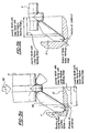
FIG. 5a is an enlarged view of a portion ofFIG. 3 ; -
FIG. 5b is a view similar toFIG. 5a but illustrating another crankshaft and fillet roller for deep rolling the fillet of the illustrated crank pin; -
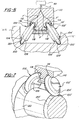
FIG. 6 is a sectional view with parts in full lines of one preferred embodiment of fillet rolling and fillet rolling tools according to this invention; -
FIG. 7 is a pictorial view of the fillet rolling construction ofFIG. 6 ; -
FIG. 8 and 9 are views respectively similar to the views ofFIG. 6 and 7 showing another preferred embodiment of this invention; -
FIG. 10 is a cross sectional view of a portion of an engine crankshaft illustrating a pin journal undercut having a compound radius; and -
FIG. 11 is a cross sectional view similar toFIG. 10 but further illustrating the deep rolling the fillet of undercut with a workpiece roller illustrating still another preferred embodiment of the invention. -
FIGS. 1 and 2 diagrammatically show portions of ametal working machine 10 illustrating some principals of deep roll strengthening of the fillets ofcrank pins 12 and main journals of acrankshaft 14 for an internal combustion engine. The crankshaft has anose end 16 mounted in achuck 18 and a flange end supported by adead point center 22 of the machine. The crankshaft can be selectively and rotatably driven about horizontal axis B by adrive motor 24 supported by amounting collar 26 on the machine housing and drivingly connected to the chuck bydrive shaft 28. Each of thecrank pins 12 is defined by side-by-side andcoaxial journal portions 30 and 32 (FIG. 3 ) providing cylindrical bearings for the connectingrods 34, 36 (FIG. 4 ) of opposing pistons in the left and right cylinders of V-block engines. - In view of the fact that the
pin journal portions - As diagrammatically illustrated in
FIGS. 2 and3 , this is accomplished in themachine 10 by upper andlower tools jaws jaw assembly 44 forming a part of the machine and supported for operation byflexible support 45. - The
upper tool 40 has a rotatable and generally cylindrical back up roller R having annular tracks T, T' operatively engaging a pair offloating workpiece rollers 46, 46' of hardened steel or other suitable material. The back up roller is rotatably mounted in the housing by suitable bearing such as disclosed inU.S. Patent No. 5,445,003 issued August 29, 1995 assigned to the assignee of this invention and hereby incorporated by reference. The workpiece rollers are operatively mounted in a cage C carried by the upper tool and generally turn on oppositely inclined axes A and A' to engage and deep roll the annular and laterally spaced undercuts or fillets F, F' providing the annular joint areas of the crankshaft journals such as the fillets, between the pins and the adjacent counter weights or bearing collars of the crankshaft. The annular working edge sections E of therollers 46, 46' are designed to fit into the journal fillet F, F' and, for adequate penetration, the radius of the roller edge has generally been formed with a 180-degree arc. The actual size of the roller edge radius should be designed to lie within the machining tolerance for the crankshaft fillet. Good overall results are obtained when the radius of the roller edge approaches the radius of the fillet. Thelower tool 41 has radially spacedsupport rollers 47 that provide the bearing and support for the crank pins as thecrankshaft 14 is being rotatably driven about its axis B and the fillets F, F' are being deep rolled. - Rolling pressure is hydraulically applied by the expansion force of a
hydraulic cylinder 48 operatively connected between the extendingends lower jaw arms pivot 53 disposed at an intermediate position along the jaw arm lengths. This arrangement provides the mechanical advantage that amplifies the jaw closure force exerted to the jaw assembly by the expansion force of thehydraulic power cylinder 48. By virtue of theflexible support 45, the upper and lower jaws and their tools are supported to float around the axis of the orbiting crank pins during rolling. Rolling pressure, transmitted by the back up roller R, and exerted by therollers 46, 46' can be increased and decreased by means ofcylinder 48 during rotational drive of the crankshaft bymotor 24 to impart concentrated annular residual stress patterns in the metal of the fillets F, F' which are among the most highly stressed cross-sectional areas of the crankshaft in engine operation. The amount of pressure as well as the number of over rolls of the fillets can be preselected to produce optimized fatigue strength. - Such rolling procedures, tooling and machinery satisfactory for many crankshafts deigns and meeting standards for improved crankshaft strengthening, limit the effective width of the crank pin journals such as width W of
pin journal 12 defined by side-by-sidecylindrical journal portions FIG. 3 . To meet new engineering requirements and standards, a limited increase in effective width is needed. To provide such increase in the effective width of crank pin journals, work rollers with smaller and compound rolling radii of the annular working edge have been utilized to deep roll the annular undercuts machined with corresponding smaller annular radii. -
FIG 5a illustrates prior art deep rolling as inFIG. 3 wherein the radius of the undercut is R = 2.286 mm and the working radius of the annular working edge E ofdeep roller 46 is R = 2.180 mm. To increase the width of the pin journal, the radius of the undercut or fillet F-I is reduced to R = 1.68mm and the radius of the peripheral annular working edge of the roller is reduced to R = 1.60mm as illustrated inFIG. 5b . With such reduction in undercut and roller working edge radii, the desired increase in width of the journal is obtained. (CompareFIGS. 5a and FIG 5b ). However, with the smaller radius of the roller working edge as used with roller of inFIG. 5b , the rolling force F fromcylinder 48 is applied directly to the annular working edge of the working roller by the back up roller R. This force is further transmitted by the working roller into the annular fillet F-I which is cold worked and compressively stressed to increase fatigue life of the journal through the diameter of the work roller and the smaller roller edge. Such highly concentrated work loads, particularly those imparted to the smaller radiused working edge of theFigure 5b work roller by the back up roller R, result in proportionally increased wear of the work rollers and sharply reduced work life thereof as discussed above. For example, with such modified work rollers, roller life is within the range of 200 -500 pieces (2000 pieces at most) as compared to the regular standard of 5,000 pieces. This reduced roller work life is generally not acceptable for high volume production so new and improved tooling is needed. -
Figures 6 and 7 illustrates one preferred embodiment of the present invention. As shown theannular working edges 100 and 100' ofwork rollers 102 and 102' respectively have small working radii, r' which may be 1.68mm and equal to the small working radius of the annular working edge of the work roller ofFig. 5b to provide the desired increase in width of the pin journal as discussed above. However, the work life ofwork roller 102, 102' is materially increased by providingannular shoulders edges 100 and 100' of the associated working rollers. - The load or rolling force F from the
cylinder 48 is split by the annular contact shoulders 116, 118 and 116' and 118' of the back up roller 110 which respectively and rollingly contact the annular side shoulders 104, 106 and 104' and 106' of the two working rollers. As illustrated by force arrows F' inFIG. 6 the rolling loads are not directed onto the annular working edges of the workpiece rollers but are imparted to the shoulders on either side thereof. With this division and spread of load F applied to the working rollers by the back-up roller, there is materially increased working life of the back-up roller and more particularly of each of theworkpiece roller 102, 102' in rollingfillets 120, 120'. This construction resultantly meets productivity requirements and can reach or exceed 5000 pieces. As in the prior art, thefillets 120, 120' are formed between the journal and an adjacent counterweight (105, 105'). -
FIGS. 8 and 9 are views of another preferred embodiment of the present invention with the annular workingedges 200 and 200' ofwork rollers 202 and 202' formed with variable radii. The back uproller 204 has annular grooves or tracks 206, 206' to receive with clearance the annular working edges 200, 200' of the working roller, the back-up roller is formed with spaced annular contact shoulders 208, 210 and 208' and 210' with inner annular contact surfaces to physically engage the hub-like annular contact shoulders 212, 214, 212', 214' formed on either side of the annular working edges 200, 200' of the working rollers. - With the variable radiused and smaller working edges, the undercuts or
fillets 218, 218' of the pin journal ofcrankshaft 219 are deep rolled and the increased width of the side byside journals 220, 220' is obtained. Because the rolling loads between the back up and working rollers are removed from the annular working edges of the rollers and are divided and directed onto the side contact shoulders there is increased tool life of the fillet and the back up rollers. -
FIG. 10 illustrates the gain G in the width ofpin journal 300 ofcrankshaft 302 by employing a compound radius for the annular undercut 304. The concave curved profile of the annular undercut 304 is shown in full lines with centers c and c'. For example, an undercut with the compound radii of 1.3000 and 0.6200 mm respectively provides an undercut width of 2.0447 mm. This provides a pin journal width gain G of 0.4332 mm over a normal undercut having only the center c and a single radius of 1.300 providing a larger undercut width w of 2.4779 mm. Since such fillets require deep rolling to increase strength, awork roller 310 having anannular rolling edge 312 with a compound curvature profiled to operatively fit within the annular undercut 304. As in the other embodiments of the present invention, thebackup roller 312 of this embodiment has annular contact shoulders 314 and 316, which physically engage the annular side shoulders 318 and 320 of theworkpiece roller 310. Thebackup roller 312 is furthermore provided with a centralizedannular groove 322, which receives with clearance the annular workingedge 312 of the workpiece roller. - With this invention, the rolling force F is divided and spread by the backup roller and directed onto the laterally spaced side shoulders of the workpiece roller as shown by force arrows F' and F". The fillet rolling force is then recombined and directed into the fillet by the workpiece rollers which works and compressively stresses the fillets of the pin journals. With the rolling force between the back up rollers divided, there is reduced workpiece roller wear as compared to prior work -back up roller designs.
- The invention has been described in an illustrative manner, and it is to be understood that the terminology, which has been used, is intended to be in the nature of word of description rather than limitation.
- Obviously, many modifications and variations of the present invention are possible in the light of the above teachings. It is, therefore, to be understood that within the scope of the appended claims the invention may be practiced otherwise than specifically described.
Claims (4)
- A rolling tool for compressively rolling annular fillets (120, 120'; 218, 218') of journals (220, 220'; 300) of a crankshaft (219; 302) for an internal combustion engine comprising a rotatable back-up roller (110; 204) having at least one annular and recessed track or groove (112, 114; 206, 206'; 322) formed therein defined between spaced load transmitting annular shoulders (116, 118, 116', 118'; 208, 210, 208', 210'; 314, 316), an annular workpiece roller (102, 102'; 202, 202'; 310) of a predetermined diameter with an annular working edge (100, 100'; 200, 200'; 312) having at least one predetermined radius, characterised in that said annular workpiece roller has a pair of annular shoulders (104, 106, 104', 106'; 212, 214, 212', 214'; 318, 320) of a smaller diameter than the diameter of the annular working edge for rolling contact with the spaced shoulders of the back up roller for receiving rolling loads from the back up roller.
- A rolling tool as set forth in claim 1 wherein said annular workpiece roller (102, 102'; 202, 202'; 310) is for direct working engagement with the annular undercut defining the fillet formed between a journal (220, 220'; 300) and an adjacent counterweight (105, 105'), and said annular back up roller (110; 204) is for direct operative engagement with the workpiece roller, said workpiece roller having a transversely curved working surface to operatively fit into the transverse curvature of the fillet, said shoulders (104, 106, 104', 106', 212, 214, 212', 214', 318, 320) of said workpiece being positioned on either side of said annular working edge, said annular groove (112, 114; 206, 206'; 322) for receiving said annular working edge of said workpiece roller.
- A rolling tool as set forth in any preceding claim, wherein said annular shoulders (104, 106, 104', 106'; 212, 214, 212', 214'; 318, 320) of said workpiece roller are on opposite sides of said annular working edge, said annular groove (112, 114; 206, 206'; 322) for receiving with clearance said annular working edge of said workpiece roller and said back up roller having said shoulders (116, 118, 116', 118'; 210, 208, 210', 208'; 314, 316) for contacting the annular shoulders on said workpiece roller so that a fillet rolling load applied to said back up roller is divided and spread to the workpiece roller through the annular shoulders thereof.
- A rolling tool as set forth in any preceding claim, wherein said rolling tool is for rolling the fillets of the pins of a crankshaft (302) having a compound radius undercut (304), said annular rolling edge (312) of said workpiece roller (310) having a compound radius rolling edge that operatively corresponds to the compound radius of the undercut.
Applications Claiming Priority (2)
| Application Number | Priority Date | Filing Date | Title |
|---|---|---|---|
| US09/707,449 US6393885B1 (en) | 2000-11-07 | 2000-11-07 | Tooling for deep rolling fillets of crankshaft journals |
| US707449 | 2000-11-07 |
Publications (3)
| Publication Number | Publication Date |
|---|---|
| EP1211026A2 EP1211026A2 (en) | 2002-06-05 |
| EP1211026A3 EP1211026A3 (en) | 2003-11-05 |
| EP1211026B1 true EP1211026B1 (en) | 2008-03-05 |
Family
ID=24841742
Family Applications (1)
| Application Number | Title | Priority Date | Filing Date |
|---|---|---|---|
| EP01308252A Expired - Lifetime EP1211026B1 (en) | 2000-11-07 | 2001-09-27 | Rolling and roller tools, roller constructions and roller equipment |
Country Status (3)
| Country | Link |
|---|---|
| US (1) | US6393885B1 (en) |
| EP (1) | EP1211026B1 (en) |
| DE (1) | DE60133076T2 (en) |
Families Citing this family (35)
| Publication number | Priority date | Publication date | Assignee | Title |
|---|---|---|---|---|
| DE50204743D1 (en) * | 2001-05-28 | 2005-12-08 | Hegenscheidt Mfd Gmbh & Co Kg | Device for deep rolling punctures and radii of bearings of crankshafts |
| DE10209301C1 (en) * | 2002-03-02 | 2003-03-27 | Hegenscheidt Mfd Gmbh & Co Kg | Machine for installing rollers in fixed roller head in machine tool has double support prism attached to periphery of fixed roller |
| DE10235957B4 (en) * | 2002-08-06 | 2005-01-20 | Hegenscheidt-Mfd Gmbh & Co. Kg | Process for finishing crankshafts for motor vehicle engines |
| DE10308124B3 (en) * | 2003-02-26 | 2004-09-23 | Hegenscheidt-Mfd Gmbh & Co. Kg | Process for deep rolling transitions between journals and cheeks of crankshafts |
| US20070251070A1 (en) * | 2003-11-20 | 2007-11-01 | Amherd Rene | Roller Holder Unit |
| US8267432B2 (en) * | 2004-03-26 | 2012-09-18 | Victaulic Company | Coupling having angularly oriented key surfaces |
| AU2005228380B2 (en) * | 2004-03-26 | 2010-07-15 | Victaulic Company | Pipe coupling having keys with camming surfaces |
| US7188497B2 (en) * | 2005-04-07 | 2007-03-13 | International Engine Intellectual Property Company, Llc | Method for straightening an eccentric shaft |
| DE102005021793B4 (en) * | 2005-05-11 | 2007-03-29 | Maschinenfabrik Alfing Kessler Gmbh | Method and system for hardening transition radii of a shaft |
| US7828158B2 (en) * | 2005-07-14 | 2010-11-09 | Displays Plus, Inc. | Merchandise dispensing apparatus providing theft deterrence |
| EP1870605A1 (en) * | 2006-06-20 | 2007-12-26 | Georg Fischer Automotive AG | Workpiece, especially a crankshaft, with an improved dynamic strength |
| EP1779972B1 (en) * | 2006-10-23 | 2008-12-17 | Cornelius Reuss | Method and apparatus for hardening crankshafts |
| DE102007028888B4 (en) * | 2007-06-20 | 2015-07-23 | Maschinenfabrik Alfing Kessler Gmbh | Method for increasing the strength of a component |
| DE202007016471U1 (en) * | 2007-11-24 | 2008-03-13 | Hegenscheidt-Mfd Gmbh & Co. Kg | Device for deep rolling of transition radii on crankshafts |
| US8282136B2 (en) | 2008-06-30 | 2012-10-09 | Mueller International, Llc | Slip on groove coupling with multiple sealing gasket |
| DE102010056616A1 (en) * | 2010-12-23 | 2012-06-28 | Hegenscheidt-Mfd Gmbh & Co. Kg | Method for straightening crankshafts |
| DE202011103888U1 (en) * | 2011-07-28 | 2011-09-07 | Hegenscheidt-Mfd Gmbh & Co. Kg | Fixed roller |
| USD696751S1 (en) | 2011-10-27 | 2013-12-31 | Mueller International, Llc | Slip-on gasket |
| USD680630S1 (en) | 2011-11-21 | 2013-04-23 | Mueller International, Llc | Slip-on coupling assembly |
| USD680629S1 (en) | 2011-11-21 | 2013-04-23 | Mueller International, Llc | Slip-on coupling segment |
| US20130125373A1 (en) | 2011-11-21 | 2013-05-23 | Philip W. Bancroft | Coupling with projections having angularly oriented surface portions |
| US9039046B2 (en) | 2012-01-20 | 2015-05-26 | Mueller International, Llc | Coupling with tongue and groove |
| US9500307B2 (en) | 2012-01-20 | 2016-11-22 | Mueller International, Llc | Slip-on coupling gasket |
| US9194516B2 (en) | 2012-01-20 | 2015-11-24 | Mueller International, Llc | Slip-on coupling |
| US9534715B2 (en) | 2012-01-20 | 2017-01-03 | Mueller International, Llc | Coupling gasket with multiple sealing surfaces |
| US9168585B2 (en) | 2012-11-02 | 2015-10-27 | Mueller International, Llc | Coupling with extending parting line |
| US9032839B2 (en) * | 2013-06-26 | 2015-05-19 | Caterpillar Inc. | Crankshaft undercut fillet |
| CN103481014B (en) * | 2013-09-17 | 2016-06-01 | 奇瑞汽车股份有限公司 | Engine crankshaft fillet rolling and reinforcing method |
| WO2015155414A1 (en) * | 2014-04-10 | 2015-10-15 | Wärtsilä Finland Oy | An on-site residual stress creation tool for and method of treating a crankshaft bearing surface and/or crankshaft bearing fillet |
| CN104148878A (en) * | 2014-08-08 | 2014-11-19 | 滨州海得曲轴有限责任公司 | Crankshaft swinging and rolling device |
| CN104191157A (en) * | 2014-08-08 | 2014-12-10 | 滨州海得曲轴有限责任公司 | Crankshaft six-wheel rolling device |
| JP6495798B2 (en) * | 2015-10-20 | 2019-04-03 | 株式会社スギノマシン | Burnishing method, roller and roller burnishing tool |
| US10161014B2 (en) | 2016-01-08 | 2018-12-25 | Ford Motor Company | Laser hardened crankshaft |
| CN109108572A (en) * | 2018-10-19 | 2019-01-01 | 淄柴动力有限公司 | Middle low-speed marine diesel engine crankshaft fillet and the compound finish rolling hardening device of axle journal and technique |
| CN112171212A (en) * | 2020-10-10 | 2021-01-05 | 河北华北柴油机有限责任公司 | Small-inner-concave arc contour surface precision machining and strengthening process |
Family Cites Families (8)
| Publication number | Priority date | Publication date | Assignee | Title |
|---|---|---|---|---|
| JPS5910433A (en) * | 1982-07-08 | 1984-01-19 | Honda Motor Co Ltd | Roll working device of fillet part |
| JPS59101228A (en) * | 1982-11-30 | 1984-06-11 | Hino Motors Ltd | Method and device for straightening bend of crankshaft |
| EP0167659B2 (en) * | 1984-07-09 | 1993-10-13 | Toyoda Koki Kabushiki Kaisha | Device for rolling fillets of journals and crankpins |
| US5445003A (en) | 1994-01-03 | 1995-08-29 | Hegenscheidt Corporation | Engine crank pin rolling equipment, rolling tool and method of rolling adjacent and offset crank pins |
| JP3593753B2 (en) * | 1995-08-04 | 2004-11-24 | 日産自動車株式会社 | Fillet rolling processing apparatus and flaw determination method in this apparatus |
| DE19722308C1 (en) * | 1997-05-28 | 1998-04-16 | Hegenscheidt Mfd Gmbh | Static cylinder machine for crankshafts |
| US6272896B1 (en) * | 1999-12-23 | 2001-08-14 | Daimlerchrysler Corporation | Secondary (back-up) roller design for the fillet rolling of the crankshaft |
| US6253590B1 (en) * | 2000-04-25 | 2001-07-03 | Lonero Engineering Company | Deep rolling tool mechanism with novel pin supported cage design |
-
2000
- 2000-11-07 US US09/707,449 patent/US6393885B1/en not_active Expired - Fee Related
-
2001
- 2001-09-27 DE DE60133076T patent/DE60133076T2/en not_active Expired - Lifetime
- 2001-09-27 EP EP01308252A patent/EP1211026B1/en not_active Expired - Lifetime
Also Published As
| Publication number | Publication date |
|---|---|
| DE60133076D1 (en) | 2008-04-17 |
| EP1211026A3 (en) | 2003-11-05 |
| US6393885B1 (en) | 2002-05-28 |
| EP1211026A2 (en) | 2002-06-05 |
| DE60133076T2 (en) | 2009-03-12 |
Similar Documents
| Publication | Publication Date | Title |
|---|---|---|
| EP1211026B1 (en) | Rolling and roller tools, roller constructions and roller equipment | |
| US5445003A (en) | Engine crank pin rolling equipment, rolling tool and method of rolling adjacent and offset crank pins | |
| AU2002216738B2 (en) | Flange bearing | |
| US5538473A (en) | Constant velocity universal joint | |
| CA2184624C (en) | Deep rolling split-pin fillets of crankshafts | |
| US6094956A (en) | Support tool for deep rolling crankshaft fillets | |
| CA2682995C (en) | Crank drive | |
| AU2002216738A1 (en) | Flange bearing | |
| US2983158A (en) | Chain with intimately united bushing and side plate, and method of making same | |
| US10092993B2 (en) | Method and tool for increasing the strength of shafts, in particular of crankshafts | |
| KR890000213B1 (en) | Method and device of forming a precision ball track | |
| EP1332952A2 (en) | Structure for standardizing parts of a roller assembly for a caterpillar construction vehicle | |
| US5303468A (en) | Method of manufacturing a crankshaft | |
| US6360574B1 (en) | Fillet rolling work roller cage | |
| US6688001B2 (en) | Method and apparatus of working plain bearing | |
| US20110192029A1 (en) | Support roll for a rolling mill | |
| GB2373560A (en) | Chain having a particular profile | |
| US6434992B1 (en) | Fillet rolling support roller | |
| CN110741170B (en) | Crankshaft and method of manufacturing crankshaft | |
| CN114850779B (en) | Repairing method of cross head bearing and cross head bearing thereof | |
| CN217713391U (en) | Local retainer | |
| CN116857295A (en) | Combined bearing for novel-structure cross shaft type universal joint | |
| SU969994A1 (en) | Method for assembling spherical joint | |
| UA23526U (en) | Universal joint |
Legal Events
| Date | Code | Title | Description |
|---|---|---|---|
| PUAI | Public reference made under article 153(3) epc to a published international application that has entered the european phase |
Free format text: ORIGINAL CODE: 0009012 |
|
| AK | Designated contracting states |
Kind code of ref document: A2 Designated state(s): AT BE CH CY DE DK ES FI FR GB GR IE IT LI LU MC NL PT SE TR |
|
| AX | Request for extension of the european patent |
Free format text: AL;LT;LV;MK;RO;SI |
|
| PUAL | Search report despatched |
Free format text: ORIGINAL CODE: 0009013 |
|
| AK | Designated contracting states |
Kind code of ref document: A3 Designated state(s): AT BE CH CY DE DK ES FI FR GB GR IE IT LI LU MC NL PT SE TR |
|
| AX | Request for extension of the european patent |
Extension state: AL LT LV MK RO SI |
|
| 17P | Request for examination filed |
Effective date: 20040413 |
|
| AKX | Designation fees paid |
Designated state(s): DE FR IT |
|
| GRAP | Despatch of communication of intention to grant a patent |
Free format text: ORIGINAL CODE: EPIDOSNIGR1 |
|
| GRAS | Grant fee paid |
Free format text: ORIGINAL CODE: EPIDOSNIGR3 |
|
| GRAA | (expected) grant |
Free format text: ORIGINAL CODE: 0009210 |
|
| AK | Designated contracting states |
Kind code of ref document: B1 Designated state(s): DE FR IT |
|
| REF | Corresponds to: |
Ref document number: 60133076 Country of ref document: DE Date of ref document: 20080417 Kind code of ref document: P |
|
| ET | Fr: translation filed | ||
| PLBE | No opposition filed within time limit |
Free format text: ORIGINAL CODE: 0009261 |
|
| STAA | Information on the status of an ep patent application or granted ep patent |
Free format text: STATUS: NO OPPOSITION FILED WITHIN TIME LIMIT |
|
| 26N | No opposition filed |
Effective date: 20081208 |
|
| PGFP | Annual fee paid to national office [announced via postgrant information from national office to epo] |
Ref country code: DE Payment date: 20130919 Year of fee payment: 13 |
|
| PGFP | Annual fee paid to national office [announced via postgrant information from national office to epo] |
Ref country code: FR Payment date: 20130919 Year of fee payment: 13 |
|
| PGFP | Annual fee paid to national office [announced via postgrant information from national office to epo] |
Ref country code: IT Payment date: 20130920 Year of fee payment: 13 |
|
| REG | Reference to a national code |
Ref country code: DE Ref legal event code: R119 Ref document number: 60133076 Country of ref document: DE |
|
| REG | Reference to a national code |
Ref country code: DE Ref legal event code: R119 Ref document number: 60133076 Country of ref document: DE Effective date: 20150401 |
|
| REG | Reference to a national code |
Ref country code: FR Ref legal event code: ST Effective date: 20150529 |
|
| PG25 | Lapsed in a contracting state [announced via postgrant information from national office to epo] |
Ref country code: DE Free format text: LAPSE BECAUSE OF NON-PAYMENT OF DUE FEES Effective date: 20150401 |
|
| PG25 | Lapsed in a contracting state [announced via postgrant information from national office to epo] |
Ref country code: FR Free format text: LAPSE BECAUSE OF NON-PAYMENT OF DUE FEES Effective date: 20140930 Ref country code: IT Free format text: LAPSE BECAUSE OF NON-PAYMENT OF DUE FEES Effective date: 20140927 |