EP1210280B1 - Transferring articles between oppositely running conveyors - Google Patents
Transferring articles between oppositely running conveyors Download PDFInfo
- Publication number
- EP1210280B1 EP1210280B1 EP00932311A EP00932311A EP1210280B1 EP 1210280 B1 EP1210280 B1 EP 1210280B1 EP 00932311 A EP00932311 A EP 00932311A EP 00932311 A EP00932311 A EP 00932311A EP 1210280 B1 EP1210280 B1 EP 1210280B1
- Authority
- EP
- European Patent Office
- Prior art keywords
- conveyors
- conveyor
- rail
- articles
- transport member
- Prior art date
- Legal status (The legal status is an assumption and is not a legal conclusion. Google has not performed a legal analysis and makes no representation as to the accuracy of the status listed.)
- Expired - Lifetime
Links
- 238000012986 modification Methods 0.000 description 4
- 230000004048 modification Effects 0.000 description 4
- 238000011144 upstream manufacturing Methods 0.000 description 4
- 241000282472 Canis lupus familiaris Species 0.000 description 2
- 230000015572 biosynthetic process Effects 0.000 description 2
- 230000000903 blocking effect Effects 0.000 description 2
- 230000008878 coupling Effects 0.000 description 2
- 238000010168 coupling process Methods 0.000 description 2
- 238000005859 coupling reaction Methods 0.000 description 2
- 230000007246 mechanism Effects 0.000 description 2
- 238000000034 method Methods 0.000 description 2
- 230000008569 process Effects 0.000 description 2
- 230000004888 barrier function Effects 0.000 description 1
- 238000000465 moulding Methods 0.000 description 1
Images



Classifications
-
- B—PERFORMING OPERATIONS; TRANSPORTING
- B65—CONVEYING; PACKING; STORING; HANDLING THIN OR FILAMENTARY MATERIAL
- B65G—TRANSPORT OR STORAGE DEVICES, e.g. CONVEYORS FOR LOADING OR TIPPING, SHOP CONVEYOR SYSTEMS OR PNEUMATIC TUBE CONVEYORS
- B65G47/00—Article or material-handling devices associated with conveyors; Methods employing such devices
- B65G47/34—Devices for discharging articles or materials from conveyor
- B65G47/46—Devices for discharging articles or materials from conveyor and distributing, e.g. automatically, to desired points
- B65G47/51—Devices for discharging articles or materials from conveyor and distributing, e.g. automatically, to desired points according to unprogrammed signals, e.g. influenced by supply situation at destination
- B65G47/5104—Devices for discharging articles or materials from conveyor and distributing, e.g. automatically, to desired points according to unprogrammed signals, e.g. influenced by supply situation at destination for articles
- B65G47/5109—Devices for discharging articles or materials from conveyor and distributing, e.g. automatically, to desired points according to unprogrammed signals, e.g. influenced by supply situation at destination for articles first In - First Out systems: FIFO
- B65G47/5113—Devices for discharging articles or materials from conveyor and distributing, e.g. automatically, to desired points according to unprogrammed signals, e.g. influenced by supply situation at destination for articles first In - First Out systems: FIFO using endless conveyors
- B65G47/5118—Devices for discharging articles or materials from conveyor and distributing, e.g. automatically, to desired points according to unprogrammed signals, e.g. influenced by supply situation at destination for articles first In - First Out systems: FIFO using endless conveyors with variable accumulation capacity
- B65G47/5131—Devices for discharging articles or materials from conveyor and distributing, e.g. automatically, to desired points according to unprogrammed signals, e.g. influenced by supply situation at destination for articles first In - First Out systems: FIFO using endless conveyors with variable accumulation capacity by relative displacement between conveyors or conveyor parts and bridging means therebetween
-
- B—PERFORMING OPERATIONS; TRANSPORTING
- B65—CONVEYING; PACKING; STORING; HANDLING THIN OR FILAMENTARY MATERIAL
- B65G—TRANSPORT OR STORAGE DEVICES, e.g. CONVEYORS FOR LOADING OR TIPPING, SHOP CONVEYOR SYSTEMS OR PNEUMATIC TUBE CONVEYORS
- B65G47/00—Article or material-handling devices associated with conveyors; Methods employing such devices
- B65G47/74—Feeding, transfer, or discharging devices of particular kinds or types
- B65G47/76—Fixed or adjustable ploughs or transverse scrapers
- B65G47/766—Adjustable ploughs or transverse scrapers
Definitions
- the present invention relates to a device for controlling the transfer of articles between oppositely running conveyors.
- a connecting conveyor is positioned between two oppositely running conveyors.
- the connecting conveyor may be a belt conveyor or may be a turntable.
- the connecting conveyor includes two drive wheels engageable with the conveyors, coupling means and a releasable blocking member, so that the connecting conveyor selectively moves with the conveyor, to which it is rotationally fixed, or moves in dependence of a speed differential of the two conveyors. In normal operation the mutual position of the transported articles remains unchanged.
- the connecting conveyor thereby is driven by a drive shaft and the two drive wheels, which are coupled. Formation and closure of gaps on a conveyor can be realised by coupling or blocking the drive wheels.
- An apparatus as disclosed is quite complicated and changing the formation of articles transported is not always necessary. Furthermore in many cases no connecting conveyor for physically transporting the articles is needed as it is sufficient to simply deflect them from one conveyor to the other.
- the present invention relates particularly to an improved transport device utilized for controlling the transfer of articles from a first conveyor running in a first direction onto a second conveyor running in a second opposite direction.
- An additional object of the present invention is provide a system that includes a first conveyor driven in a first direction and a second conveyor driven in a second direction, as well as an improved transport member utilized to transfer articles from the first conveyor onto the second conveyor.
- Still another important object of the present invention is to provide an article storage accumulator which permits a large number of articles to be stored in a relatively small amount of floor space.
- Yet still another object of the present invention is to provide an improved article transport member for use on conventional conveyors that is far less complicated than conventional devices.
- conveyors are a feature of the present invention, conventional conveyors are well known to those skilled in the art and need not be described herein in great detail. The features of the conveyors necessary for an understanding of the invention will be sufficiently described.
- an apparatus for controlling the flow of articles.
- This apparatus includes a first conveyor driven in a first direction to convey articles thereon in the first direction.
- a second conveyor is driven in a second opposite direction to convey articles thereon in the opposite direction.
- the first and second conveyors may be used in a conventional accumulator system.
- the conveyors extend generally side by side and parallel with a constant space defined between the inside edges thereof.
- a movable transport member is disposed within the space defined between the conveyors and comprises a bridge that extends across the space between the conveyors and is generally flush with the upper surfaces of the conveyors.
- the transport member is drivingly engaged by both of the conveyors so as to move linearly between the conveyors depending on a speed differential of the conveyors.
- the transport member and bridge move in the direction of the faster conveyor. If both conveyors are moving linearly in opposite directions but at the same speed, the transport member remains stationary relative to the conveyors.
- An article transfer member is carried by the transport member and is operably disposed relative to one of the conveyors, for example the first conveyor, to contact and transfer articles from the first conveyor to the second conveyor.
- the transport member may comprise a relatively simple deflecting bar or rail.
- the transport member may comprise a drive wheel that is simultaneously engaged by drive lugs on each of the conveyors.
- the drive wheel has gear teeth engaged by the drive lugs so as to continuously rotate so long as at least one of the conveyors is moving.
- the bridge member comprises a deformable rail having dimensions so as to fit between the conveyors within the space defined between the conveyor edges.
- the rail has a longitudinal length to define a length of the bridge member.
- the bridge member is comprised of a plurality of pivotally connected links having an upper surface that is generally flush with the upper surface of the conveyors. The links are pivotally connected and thus deformable so that the transport member and bridge can easily follow curves or turns in the conveyors.
- the transport member also includes a deflecting rail carried by the transport member longitudinally distanced from the bridge.
- This deflecting rail is oriented so as to deflect articles that are transferred from the first conveyor over the bridge to a middle portion of the second conveyor.
- This deflecting rail may be spring loaded toward the second conveyor.
- the transport member may comprise any manner of frame or structure.
- the transport member comprises a relatively simple carriage that is connected at one end to a drive wheel and at an opposite end to a support wheel.
- the drive wheel may be configured as discussed above with gear teeth that engage with drive lugs on the under side of the conveyors.
- the article transfer member is carried by this carriage member.
- the support wheel is longitudinally distanced from the drive wheel and rigidly connected to the drive wheel by means of the carriage to ensure that the carriage and article transfer member remain aligned at all times relative to the conveyors, particularly through turns or bends in the conveyors.
- Apparatus 10 includes a first conveyor 14 that moves in a first direction, and second conveyor 20 that moves in a second opposite direction.
- the first and second conveyors 14,20 are arranged in a side-by-side and parallel relationship such that a constant space 26 is defined between the inside edges of the conveyors.
- Conveyors 14,20 may be formed as any conventional conveyor, including conventional link-type conveyors, belt conveyors, and the like.
- the present invention is not limited to any particular conveying system and has application in any system wherein articles are to be moved from a first conveyor onto a second conveyor.
- a conventional system incorporating such oppositely moving and parallel conveyors is an accumulator system used for accumulating and storing articles between an upstream receiving station and a downstream delivery station.
- a detailed description of an accumulator system is provided in co-pending U.S. Patent Application Serial No. 09/235,888 entitled "Apparatus for Controlling the Flow of Articles". The '888 application is incorporated herein in its entirety for all purposes.
- Conveyors 14,20 may be formed of individual interconnected segments or links 16,22, as is well understood by those skilled in the art. Conveyors 14,20 define upper conveying surfaces 18,24 upon which articles are placed to be conveyed by the conveyors.
- a detailed view of segments of conventional conveyors comprised of individual interconnected links or segments 16,22 is provided in Figures 4 and 5.
- the underside of the conveyors 14,20 are provided with a number of equally spaced drive dogs 72. These drive dogs 72 are conventionally engaged by a drive motor or other mechanism for moving the conveyor in the conveying direction.
- Equally spaced apart conveyor lugs 36 are also provided on the underside of conveyors 14,20. These drive lugs 36 are engaged by a drive wheel 32 of the article transport member, as shown in Figure 3 and discussed in greater detail below.
- Channel 52 may have a generally U-shaped channel.
- Channel 52 may be defined by segments 54 that are attached onto the inside edges of conveyors 14,20.
- channels 52 may be formed integral with the conveyor segments 16,22 in the molding process. Channels 52 are engaged by links 46,62 of the movable transport member, as discussed in greater detail below.
- a movable transport member, generally 28, is provided to transport articles 12 from the first conveyor 14 onto second conveyor 22, as generally illustrated in Figure 2.
- Movable transport member 28 is disposed within the space defined between conveyors 14,22 and comprises a bridge 30 that extends between the conveyors and is generally flush with upper surfaces 18,24 of conveyors 14,20.
- the bridge 30 comprises a deformable rail member, generally 44.
- Rail member 44 has dimensions so as to fit between conveyors 14,20 within space 26 over a longitudinal length thereof.
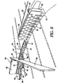
- rail 44 is comprised of a plurality of pivotally connected links 46, as particularly illustrated in Figure 6.
- Links 46 have a height such that their upper surface 50 is flush with the upper surfaces 18,24 of conveyors 14,20.
- Links 46 may be molded in a conventional process from any suitable plastic or other material. Links 46 are pivotally connected to each other by way of pivot pins 48.
- the rigid links 46 when connected form a deformable rail 44 defining bridge 30.
- Links 46 include outwardly extending guide tabs 51.
- -Guide tabs 51 slide within and along guide channels 52 defined on the inside edges of conveyors 14,20.
- Transport member 28 may be drivingly engaged by conveyors 14,20 so as to move linearly between the conveyors depending on a speed differential of the conveyors thereby causing the transport member to move in the direction of the faster of the conveyors.
- transport member 28 includes, for example, a drive wheel 32.
- Drive wheel 32 includes gear teeth 34 that are engaged by drive lugs 36 on the underside of each of conveyors 14,20, as particularly illustrated in Figure 3. Accordingly, as can be understood from Figure 3, if conveyors 14 and 20 move in opposite directions but at equal speeds, drive wheel 32 will continuously rotate but will remain in the same relative linear position. Guide wheel 32 will advance in the direction of the faster of the conveyors.
- other drive mechanisms may also be used for moving transport member 28, including separate chain drives, differential gear arrangement, servos, etc.
- Deformable rail 44 or bridge 30 is connected to drive wheel 32 such that drive wheel 32 either pushes or pulls deformable rail 44 between conveyors 14,20.
- Drive wheel 32 is formed by an upper section 33 and a lower section 35, as particularly seen in Figures 3 and 6.
- Upper section 33 has drive teeth 34 defined around the circumference thereof.
- Lower section 35 has a wheel groove or channel 68 defined around the circumference thereof. Channel 68 rides along wheel guides 70 disposed on structure below conveyors 14,24, as particularly illustrated in Figure 4 and in the cross-sectional views of Figures 7 and 8.
- Article transport member 28 may also include a support wheel 40 longitudinally distanced from drive wheel 32.
- Support wheel 40 is rigidly connected with drive wheel 32 by, for example, a carriage member for device 38.
- Support wheel 40 also includes wheel groove 68 formed on the circumference thereof that engages with wheel guides 70, as with drive wheel 32.
- Support wheel 40 and carriage 38 ensure that the drive wheel and deformable rail 44 are always aligned relative to the conveyors, particularly as transport member 28 moves through curves or bends of the conveyor system.
- carriage 38 is configured by a relatively simple upright or rigid member.
- Carriage 38 also includes tabs or guides 39 formed thereon that also engage within conveyor guide channels 52 defined on the inside edges of conveyors 14,20.
- Deformable rail 44, and particularly links 46, are attached by any conventional manner onto carriage 38.
- An article transfer member, generally 42, is carried by transport member 28.
- transfer member 42 may include a relatively rigid deflecting bar 64 that is oriented transversely to the first conveyor. Articles conveyed on first conveyor 14 impinge upon bar 64 and are directed to slide across bridge 30 between conveyors 14,20 formed by deformable rail 44 as particularly illustrated in Figure 2. Thus, the articles simply slide over bridge 30 and onto second conveyor 20 moving in the opposite direction of conveyor 14.
- Article transfer member 42 can take on any manner of shape or configuration, for example a curved plate, rail, or the like.
- article transfer member in the form of deflecting bar 64 is carried by transport member 28 by means of a brace 66.
- deflecting bar 64 is rigidly disposed relative to transport member 28, it may desired that deflecting bar 64 have a length to ensure that it will extend completely across conveyor 14 even as transport member 28 is driven around curves or bends in the conveyors.
- deflecting bar 64 extends over the edge of first conveyor 14, as generally illustrated in Figures 1 and 2. It should be appreciated that other devices may also be utilized to account for movement of the transfer member 42 around bends or curves.
- transport member 28 include a deflecting rail, generally 58 that is longitudinally distanced from bridge 30.
- deflecting rail 58 is carried by a plurality of interconnected fence links 62. Links 62 have a height so as to extend well above the upper surfaces of conveyors 14,20 and thus form a fence or barrier that defines the limit of bridge 30. In other words, bridge 30 is defined between deflecting bar 64 and the beginning of fence links 62.
- Deflecting rail 58 is attached to the first of links 62 in the embodiment illustrated and may also be spring loaded towards second conveyor 20 by means of spring 60. Rail 58 ensures that articles transferred onto second conveyor 20 are moved towards a middle portion or section of the second conveyor.
- Figures 7-10 are cross-sectional views of the apparatus 10 according to the invention taken along the lines indicated in Figure 3. Figures 7-10 give a detailed cross-sectional view of the invention.
- bridge 30 or deformable rail 44 need not be formed by individual interconnected links, but may be formed by an integral deformable piece of material.
- the arrangement between drive wheel 32 and support wheel 40 can comprise any conventional connecting configuration.
- the article transfer member 42 illustrated in the figures as a relatively simple deflecting bar 64 can take on any manner of shape or configuration.
- transfer member 42 may also be a driven or movable member.
- Various other modifications and variations are also possible in the other components of the invention. It is intended that the present invention include such modifications and variations as come within the scope of the appended claims and their equivalents.
Landscapes
- Engineering & Computer Science (AREA)
- Mechanical Engineering (AREA)
- Intermediate Stations On Conveyors (AREA)
- Branching, Merging, And Special Transfer Between Conveyors (AREA)
- Attitude Control For Articles On Conveyors (AREA)
- Structure Of Belt Conveyors (AREA)
- Special Conveying (AREA)
- Transition And Organic Metals Composition Catalysts For Addition Polymerization (AREA)
- Control Of Conveyors (AREA)
Abstract
Description
The present invention has particular application in conveyor accumulator systems wherein oppositely running and parallel conveyors are used to accumulate and store articles between an upstream receiving station and a downstream delivery station. One such accumulator system is disclosed and described in co-pending U.S. Patent Application Serial No. 09/235,888 entitled "Apparatus for Controlling the Flow of Articles."
A movable transport member is disposed within the space defined between the conveyors and comprises a bridge that extends across the space between the conveyors and is generally flush with the upper surfaces of the conveyors. The transport member is drivingly engaged by both of the conveyors so as to move linearly between the conveyors depending on a speed differential of the conveyors. In other words, the transport member and bridge move in the direction of the faster conveyor. If both conveyors are moving linearly in opposite directions but at the same speed, the transport member remains stationary relative to the conveyors. An article transfer member is carried by the transport member and is operably disposed relative to one of the conveyors, for example the first conveyor, to contact and transfer articles from the first conveyor to the second conveyor. The transport member may comprise a relatively simple deflecting bar or rail.
Claims (16)
- An apparatus (10) for controlling the flow of articles (12), comprising:characterized in thata first conveyor (14) driven in a first direction to convey articles (12) thereon in said first direction, and a second conveyor (20) driven in a second direction opposite to said first direction to convey articles (12) thereon in said second direction;said first and second conveyors (14, 20) extending side-by-side and parallel with a space (26) defined therebetween;a movable transport member (28) disposed within said space (26) defined between said conveyors (14, 20)said transport member (28) drivingly engaged by both of said conveyors (14, 20) so as to move linearly between said conveyors (14, 20) depending on a speed differential between said conveyors (14, 20) causing said transport member (28) to move in the direction of the faster of said conveyors (14, 20); andan article transfer member (42) carried by said transport member (28) and operably disposed transversely to said conveyors (14, 20)
said movable transport member (28) comprises a bridge (30) extending between said conveyors (14, 20) and is generally flush with upper surfaces (18, 24) of said conveyors (14, 20), said bridge (30) being stationary relative to said movable transport member (28) and that
said article transfer member (42) contacts and transfers articles (12) from said first conveyor (14) to said second conveyor (20). - The apparatus (10) as in claim 1, wherein said transport member (28) comprises a drive wheel (32) simultaneously engaged by drive lugs (36) on each of said conveyors (14, 20) so as to continuously rotate so long as at least one of said conveyors (14, 20) is moving.
- The apparatus (10) as in claim 1, wherein said bridge (30) comprises a deformable rail member (44) having dimensions so as to fit between said conveyors (14, 20) over a length thereof.
- The apparatus (10) as in claim 3, wherein said rail member (44) comprises a plurality of pivotally
connected links (46) having an upper surface (50) generally flush with said upper surfaces (18, 24) of said conveyors (14, 20). - The apparatus (10) as in claim 4, wherein said conveyors (14, 20) comprises guide channels (52) on inside facing edges thereof, said links (46) moveable in and along said guide channels (52).
- The apparatus (10) as in claim 5, wherein said conveyors (14, 20) comprise individual interconnected segments (16, 22), said guide channels (52) formed integral with said segments (16, 22).
- The apparatus (10) as in claim 1, wherein said article transfer member (42) comprises a deflecting bar member (64) carried by said transport member (28), said bar member (64) having a length so as to extend at least across said first conveyor (14).
- The apparatus (10) as in claim 1, further comprising a deflecting rail (58) carried by said transport member (28) longitudinally distanced from said bridge (30) and oriented so as to deflect articles (12) transferred from said first conveyor (14) over said bridge (30) to a middle portion of said second conveyor (20).
- The apparatus (10) as in claim 8, wherein said deflecting rail (58) is spring loaded towards said second conveyor (20).
- The apparatus (10) as in claim 1, wherein said transport member (28) comprises a carriage (38) connected at one end to a drive wheel (32) and at an opposite end to a support wheel (40), said drive wheel (32) having teeth (34) engaged with drive lugs (36) on said conveyors (14, 20), said article transfer member (42) carried by said carriage (38).
- The apparatus (10) as in claim 10, wherein said bridge (30) comprises a deformable rail (44) having an end connected to said carriage (38).
- An apparatus (10) as in claim 1, characterized in that
said movable transport member is a carriage member (38) having a drive wheel (32) engaged with drive lugs (36) on each of said conveyors (14, 20) so that said carriage member (38) moves along said conveyors (14, 20) depending on a speed differential between said conveyors (14, 20) causing said carriage member (38) to move in the direction of the faster of said conveyors (14, 20) and that
a longitudinally extending deformable rail member (44) is attached to said carriage member (38) so as to move therewith relative to said conveyors (14, 20), said rail member (44) being disposed between said conveyors (14, 20) and having an upper surface (50) generally flush with an upper surface (18, 24) of each of said conveyors (14, 20), and that
said article transfer member (42) extends across at least a portion of said first conveyor (14) so that articles (12) on said first conveyor (14) are deflected by said transfer member (42) over said rail member (44) and onto said second conveyor (20). - The apparatus (10) as in claim 12, wherein said carriage member (38) further comprises a support wheel (40) longitudinally distanced from said drive wheel (32).
- The apparatus (10) as in claim 12, wherein said rail member (44) comprises a plurality of interconnected links (46), said links (46) moveable within and along channels (52) defined on facing edges of said conveyors (14, 20).
- The apparatus (10) as in claim 12, further comprising a deflecting rail (58) carried by said rail member (44) longitudinally distanced from said carriage member (38) and oriented so as to deflect articles (12) transferred from said first conveyor (14) over rail member (44) to a middle portion of said second conveyor (20).
- The apparatus (10) as in claim 15, wherein said deflecting rail (58) is spring loaded towards said second conveyor (20).
Applications Claiming Priority (3)
| Application Number | Priority Date | Filing Date | Title |
|---|---|---|---|
| US365119 | 1982-04-05 | ||
| US09/365,119 US6182812B1 (en) | 1999-07-30 | 1999-07-30 | Device for transferring articles between oppositely running conveyors |
| PCT/US2000/012958 WO2001009015A1 (en) | 1999-07-30 | 2000-05-12 | Transferring articles between oppositely running conveyors |
Publications (3)
| Publication Number | Publication Date |
|---|---|
| EP1210280A1 EP1210280A1 (en) | 2002-06-05 |
| EP1210280A4 EP1210280A4 (en) | 2003-04-23 |
| EP1210280B1 true EP1210280B1 (en) | 2005-08-03 |
Family
ID=23437542
Family Applications (1)
| Application Number | Title | Priority Date | Filing Date |
|---|---|---|---|
| EP00932311A Expired - Lifetime EP1210280B1 (en) | 1999-07-30 | 2000-05-12 | Transferring articles between oppositely running conveyors |
Country Status (8)
| Country | Link |
|---|---|
| US (1) | US6182812B1 (en) |
| EP (1) | EP1210280B1 (en) |
| JP (1) | JP3769229B2 (en) |
| CN (1) | CN1144750C (en) |
| AT (1) | ATE301095T1 (en) |
| AU (1) | AU5005000A (en) |
| DE (1) | DE60021735T2 (en) |
| WO (1) | WO2001009015A1 (en) |
Families Citing this family (34)
| Publication number | Priority date | Publication date | Assignee | Title |
|---|---|---|---|---|
| US6497321B2 (en) * | 2001-03-09 | 2002-12-24 | Hartness International, Inc. | Apparatus for diverting a stream of articles |
| US6334528B1 (en) * | 2000-06-16 | 2002-01-01 | The Laitram Corporation | Variable-width spacer |
| US6698581B2 (en) * | 2000-08-29 | 2004-03-02 | Hartness International | Article guide for an apparatus for controlling the flow of articles |
| US6523669B1 (en) * | 2000-08-29 | 2003-02-25 | Hartness International, Inc. | Article guide for an apparatus for controlling the flow of articles |
| US6612420B1 (en) * | 2000-10-17 | 2003-09-02 | Hartness International, Inc. | Device for transferring articles between oppositely running conveyors |
| US6705451B2 (en) * | 2001-03-08 | 2004-03-16 | Artur Zielinski | Method and apparatus for distributing articles from a conveyor |
| US6533103B2 (en) | 2001-07-27 | 2003-03-18 | Hartness International | Transfer device for use between two conveyors |
| JP5160789B2 (en) * | 2004-02-02 | 2013-03-13 | クロネス・アクチェンゲゼルシャフト | Dynamic storage device for goods |
| US7032742B2 (en) | 2004-04-02 | 2006-04-25 | Hartness International, Inc. | Differential drive spiral accumulator apparatus |
| US7028830B2 (en) * | 2004-05-25 | 2006-04-18 | Hartness International, Inc. | Apparatus for diverting a stream of articles |
| DE202004016069U1 (en) | 2004-10-16 | 2005-12-01 | Krones Ag | Device for buffering objects |
| US7249671B2 (en) * | 2005-05-06 | 2007-07-31 | Laitram, L.L.C. | Roller-belt conveyor for accumulating and moving articles laterally across the conveyor |
| DE202005013552U1 (en) | 2005-08-27 | 2005-11-03 | Krones Ag | Dynamic storage for buffering and transporting empty bottle, has lower deflection pulleys rotating in essentially horizontal planes and connected with vertical loops by curved guides for conveyor chain |
| DE102006008123A1 (en) * | 2006-02-20 | 2007-08-23 | Krones Ag | Dynamic conveyor holding zone, for items being carried, has two conveyor paths moving in opposite directions with a transfer unit to move them from one to the other and a control unit linked to sensors |
| DE102006012148A1 (en) * | 2006-03-16 | 2007-09-20 | Krones Ag | funding |
| CA2649390A1 (en) * | 2006-04-20 | 2007-11-01 | Mark W. Spencer | Dynamic conveyance device |
| DE602006003532D1 (en) * | 2006-04-24 | 2008-12-18 | Specialty Conveyor Bv | Conveyor for transport and damming of individual products |
| DE102006035109A1 (en) * | 2006-07-29 | 2008-01-31 | Krones Ag | Conveyor device for use in bottle handling device, has conveyors separated from each other and connected with buffer over transferring points, where intermediate conveyor bypasses buffer |
| WO2009035391A1 (en) * | 2007-09-14 | 2009-03-19 | Flexlink Components Ab | Diverting device for a conveyor system and a method for diverting objects which are conveyed along a conveying track |
| DE102007062652A1 (en) * | 2007-12-24 | 2009-06-25 | Krones Ag | Article buffer |
| DE102008014831B4 (en) * | 2008-03-18 | 2016-08-18 | Krones Aktiengesellschaft | Device for buffering objects |
| FR2948649B1 (en) | 2009-07-29 | 2011-09-09 | Sidel Participations | ACCUMULATION TABLE OF ARTICLES FOR A CONVEYING FACILITY |
| NL2005846C2 (en) | 2010-12-09 | 2012-06-12 | Specialty Conveyor Bv | A transfer conveyor and a conveying system. |
| CN103380807B (en) * | 2013-08-10 | 2014-12-24 | 温州大学 | Fish killing device |
| CN103419961A (en) * | 2013-08-19 | 2013-12-04 | 宁波佳必可食品有限公司 | Can circulating conveyer device |
| CN103482343B (en) * | 2013-08-29 | 2017-03-01 | 湖州冠炯机电科技有限公司 | Conveying mechanism for hot glue ornaments |
| CN104229368A (en) * | 2014-08-21 | 2014-12-24 | 朱新成 | Logistics transportation system |
| CN104514802A (en) * | 2014-11-14 | 2015-04-15 | 蒋能龙 | Straight horizontal driving wheel |
| US9688482B2 (en) | 2015-03-17 | 2017-06-27 | Illinois Tool Works Inc. | Apparatus for buffering the flow of articles |
| CN108137245B (en) * | 2015-10-15 | 2021-02-12 | 伊利诺斯工具制品有限公司 | Device for redirecting a stream of articles |
| CN105293047B (en) * | 2015-10-28 | 2017-08-22 | 江苏新美星包装机械股份有限公司 | It is divided into the sub-bottle Song Ping mechanisms in the conveying device of two row by a row |
| DE102017212125A1 (en) * | 2017-07-14 | 2019-01-17 | Krones Ag | Conveyor storage device |
| DE102017120730A1 (en) * | 2017-09-08 | 2019-03-14 | Khs Gmbh | Device and method for aligning containers |
| US12503318B2 (en) * | 2023-03-27 | 2025-12-23 | Illinois Tool Works Inc. | Apparatus and method for accumulating a stream of articles with multiple outfeed directions |
Family Cites Families (33)
| Publication number | Priority date | Publication date | Assignee | Title |
|---|---|---|---|---|
| GB831911A (en) | 1957-09-30 | 1960-04-06 | Bratby & Hinchliffe Ltd | Improvements in or relating to rotary bottle filing tables |
| DE1262886B (en) | 1964-12-04 | 1968-03-07 | Bahlsen Werner | Intermediate storage in the conveyor path of flat, vertically adjacent pieces of cake |
| US3318439A (en) | 1965-04-12 | 1967-05-09 | Kornylac Co | Conveyor system |
| DE2307728A1 (en) | 1973-02-16 | 1974-09-05 | Windmoeller & Hoelscher | DEVICE FOR THE PRODUCTION OF ONE-SIDED OPEN BAGS SEAMED AT THE BOTTOM |
| US4018325A (en) | 1975-10-09 | 1977-04-19 | The Pillsbury Company | Automatic package accumulator |
| DE2618905C3 (en) | 1976-04-29 | 1980-09-25 | Maschinenfabrik Alfred Schmermund Gmbh & Co, 5820 Gevelsberg | Intermediate storage in the form of a transfer conveyor |
| US4063632A (en) | 1976-06-23 | 1977-12-20 | Columbia Machine, Inc. | Swingable arcuate guide for selectively orienting articles |
| CH618398A5 (en) | 1977-06-06 | 1980-07-31 | Ferag Ag | |
| US4364465A (en) * | 1980-09-19 | 1982-12-21 | Nabisco, Inc. | Collating conveyor system |
| FR2499033A1 (en) | 1981-02-03 | 1982-08-06 | Nantaise Biscuiterie | METHOD AND DEVICE FOR REGULARIZING THE TRANSFER OF IDENTICAL SOLID PRODUCTS |
| US4513858A (en) | 1981-05-18 | 1985-04-30 | Mapatent, N.V. | Horizontal accumulator |
| US4413724A (en) | 1981-05-18 | 1983-11-08 | Mapatent, N.V. | Horizontal accumulator |
| US4401020A (en) * | 1981-12-16 | 1983-08-30 | Seaco Industries | Vegetable banding apparatus |
| FR2524436B1 (en) | 1982-04-02 | 1985-09-27 | Nantaise Biscuiterie | REGULATING DEVICE FOR TRANSFERRING IDENTICAL SOLID PRODUCTS BETWEEN UPSTREAM AND DOWNSTREAM MACHINES OF DIFFERENT SPEEDS |
| JPS5953315A (en) * | 1982-09-22 | 1984-03-28 | Toyo Kanetsu Kk | conveyor equipment |
| CH667258A5 (en) | 1985-05-02 | 1988-09-30 | Ferag Ag | METHOD AND DEVICE FOR FEEDING A SEPARATING DEVICE FOR PRINTED PRODUCTS, ESPECIALLY AN INVESTOR. |
| ATE68769T1 (en) | 1986-09-08 | 1991-11-15 | Ferag Ag | METHOD AND DEVICE FOR EQUALIZING THE DISTANCE BETWEEN SUCCESSIVE PRODUCTS, IN PARTICULAR PRINTED PRODUCTS, OCCURRING IN A SHED FORMATION. |
| JPH0736898Y2 (en) | 1987-02-19 | 1995-08-23 | エービー テトラパック | Distribution and transfer device for conveyed articles on conveyor |
| DE3742955A1 (en) | 1987-12-18 | 1989-06-29 | Focke & Co | DEVICE FOR THE PRODUCTION AND PACKAGING OF CIGARETTES |
| US4989718A (en) | 1989-08-23 | 1991-02-05 | Hartness International, Inc. | Surge control method and apparatus |
| US5067857A (en) | 1990-04-27 | 1991-11-26 | Coors Brewing Company | Apparatus for diverting the movement of cylindrical bodies |
| JP3222181B2 (en) * | 1992-03-19 | 2001-10-22 | 松下電器産業株式会社 | Work supply device with buffer mechanism |
| JP3084911B2 (en) * | 1992-04-15 | 2000-09-04 | 松下電器産業株式会社 | Round belt conveyor and method of using the same |
| US5413213A (en) | 1992-07-25 | 1995-05-09 | Korber Ag | Apparatus for transporting mass flows of articles |
| US5690463A (en) | 1992-07-31 | 1997-11-25 | Nippon Filing Co., Ltd. | Book storage/retrieval apparatus |
| DE4325380C2 (en) | 1993-07-24 | 1996-02-08 | Schierholz Kg Louis | Hanging conveyor system |
| US5350050A (en) | 1993-09-09 | 1994-09-27 | Donald L. Collver | Continuous vertical conveyor |
| US5417317A (en) | 1994-04-29 | 1995-05-23 | Atlas Pacific Engineering Company | Apparatus for segregating and feeding fruit from a bulk supply |
| DE4416893C1 (en) | 1994-05-13 | 1995-06-14 | Licentia Gmbh | Guide device for mail distributing conveyors |
| CH690646A5 (en) | 1995-05-09 | 2000-11-30 | Ferag Ag | An apparatus for conveying objects. |
| SE504804C2 (en) | 1995-08-24 | 1997-04-28 | Swedefish Machinery Ab | Device for transferring objects from a first to a second conveyor |
| US5903464A (en) | 1997-03-07 | 1999-05-11 | Stingel, Jr.; Frederick John | Conveying system and method for mixing stacked articles |
| US6260688B1 (en) * | 1999-01-22 | 2001-07-17 | Hartness International | Apparatus for controlling the flow of articles |
-
1999
- 1999-07-30 US US09/365,119 patent/US6182812B1/en not_active Expired - Lifetime
-
2000
- 2000-05-12 JP JP2001514223A patent/JP3769229B2/en not_active Expired - Lifetime
- 2000-05-12 DE DE60021735T patent/DE60021735T2/en not_active Expired - Lifetime
- 2000-05-12 EP EP00932311A patent/EP1210280B1/en not_active Expired - Lifetime
- 2000-05-12 AT AT00932311T patent/ATE301095T1/en not_active IP Right Cessation
- 2000-05-12 CN CNB008109966A patent/CN1144750C/en not_active Expired - Lifetime
- 2000-05-12 WO PCT/US2000/012958 patent/WO2001009015A1/en not_active Ceased
- 2000-05-12 AU AU50050/00A patent/AU5005000A/en not_active Abandoned
Also Published As
| Publication number | Publication date |
|---|---|
| WO2001009015A1 (en) | 2001-02-08 |
| CN1144750C (en) | 2004-04-07 |
| JP3769229B2 (en) | 2006-04-19 |
| EP1210280A1 (en) | 2002-06-05 |
| DE60021735T2 (en) | 2006-04-20 |
| DE60021735D1 (en) | 2005-09-08 |
| AU5005000A (en) | 2001-02-19 |
| CN1365334A (en) | 2002-08-21 |
| JP2003506288A (en) | 2003-02-18 |
| EP1210280A4 (en) | 2003-04-23 |
| ATE301095T1 (en) | 2005-08-15 |
| US6182812B1 (en) | 2001-02-06 |
Similar Documents
| Publication | Publication Date | Title |
|---|---|---|
| US6182812B1 (en) | Device for transferring articles between oppositely running conveyors | |
| EP1326793B1 (en) | Device for transferring articles between oppositely running conveyors | |
| US6390285B2 (en) | Conveyor system for conveying and accumulating objects | |
| EP1794069B1 (en) | Apparatus and method for high speed conveyor switching | |
| CN101395075B (en) | transfer converter | |
| US5217103A (en) | Conveyor | |
| US4760908A (en) | Sorter conveyor | |
| KR960037532A (en) | Conveying equipment | |
| CA2310405C (en) | Conveying apparatus and corresponding transporting means | |
| CA3204657A1 (en) | Material handling apparatus with vehicle track for reducing vehicle damage | |
| EP1957385B1 (en) | A device for buffering products and a method of operating this | |
| US6415905B1 (en) | Transport device | |
| US9856093B2 (en) | Apparatus for diverting a stream of articles | |
| EP0425021A1 (en) | Conveyor | |
| JPH05278825A (en) | Buffer device and driving system | |
| EP0749920B1 (en) | Article distribution apparatus | |
| CN113173373B (en) | Conveyor and conveying system | |
| CN220264286U (en) | Conveying lane changing device | |
| JPH04179620A (en) | Laterally-moving device for conveyance | |
| JPH07187133A (en) | Automatic collecting and supplying apparatus | |
| JP3044973B2 (en) | Conversion device | |
| IT202200026613A1 (en) | DIVIDING APPARATUS | |
| JPH0733009A (en) | Conveyance equipment with movable element | |
| CN117043084A (en) | Item classification method and item classification device |
Legal Events
| Date | Code | Title | Description |
|---|---|---|---|
| PUAI | Public reference made under article 153(3) epc to a published international application that has entered the european phase |
Free format text: ORIGINAL CODE: 0009012 |
|
| 17P | Request for examination filed |
Effective date: 20020208 |
|
| AK | Designated contracting states |
Kind code of ref document: A1 Designated state(s): AT BE CH CY DE DK ES FI FR GB GR IE IT LI LU MC NL PT SE |
|
| AX | Request for extension of the european patent |
Free format text: AL;LT;LV;MK;RO;SI |
|
| A4 | Supplementary search report drawn up and despatched |
Effective date: 20030306 |
|
| RIC1 | Information provided on ipc code assigned before grant |
Ipc: 7B 65G 47/51 B Ipc: 7B 65G 37/00 A |
|
| 17Q | First examination report despatched |
Effective date: 20040422 |
|
| GRAP | Despatch of communication of intention to grant a patent |
Free format text: ORIGINAL CODE: EPIDOSNIGR1 |
|
| GRAS | Grant fee paid |
Free format text: ORIGINAL CODE: EPIDOSNIGR3 |
|
| GRAA | (expected) grant |
Free format text: ORIGINAL CODE: 0009210 |
|
| AK | Designated contracting states |
Kind code of ref document: B1 Designated state(s): AT BE CH CY DE DK ES FI FR GB GR IE IT LI LU MC NL PT SE |
|
| PG25 | Lapsed in a contracting state [announced via postgrant information from national office to epo] |
Ref country code: NL Free format text: LAPSE BECAUSE OF FAILURE TO SUBMIT A TRANSLATION OF THE DESCRIPTION OR TO PAY THE FEE WITHIN THE PRESCRIBED TIME-LIMIT Effective date: 20050803 Ref country code: FI Free format text: LAPSE BECAUSE OF FAILURE TO SUBMIT A TRANSLATION OF THE DESCRIPTION OR TO PAY THE FEE WITHIN THE PRESCRIBED TIME-LIMIT Effective date: 20050803 Ref country code: AT Free format text: LAPSE BECAUSE OF FAILURE TO SUBMIT A TRANSLATION OF THE DESCRIPTION OR TO PAY THE FEE WITHIN THE PRESCRIBED TIME-LIMIT Effective date: 20050803 Ref country code: CH Free format text: LAPSE BECAUSE OF FAILURE TO SUBMIT A TRANSLATION OF THE DESCRIPTION OR TO PAY THE FEE WITHIN THE PRESCRIBED TIME-LIMIT Effective date: 20050803 Ref country code: LI Free format text: LAPSE BECAUSE OF FAILURE TO SUBMIT A TRANSLATION OF THE DESCRIPTION OR TO PAY THE FEE WITHIN THE PRESCRIBED TIME-LIMIT Effective date: 20050803 Ref country code: BE Free format text: LAPSE BECAUSE OF FAILURE TO SUBMIT A TRANSLATION OF THE DESCRIPTION OR TO PAY THE FEE WITHIN THE PRESCRIBED TIME-LIMIT Effective date: 20050803 |
|
| REG | Reference to a national code |
Ref country code: GB Ref legal event code: FG4D |
|
| REG | Reference to a national code |
Ref country code: CH Ref legal event code: EP |
|
| REG | Reference to a national code |
Ref country code: IE Ref legal event code: FG4D |
|
| REF | Corresponds to: |
Ref document number: 60021735 Country of ref document: DE Date of ref document: 20050908 Kind code of ref document: P |
|
| PG25 | Lapsed in a contracting state [announced via postgrant information from national office to epo] |
Ref country code: DK Free format text: LAPSE BECAUSE OF FAILURE TO SUBMIT A TRANSLATION OF THE DESCRIPTION OR TO PAY THE FEE WITHIN THE PRESCRIBED TIME-LIMIT Effective date: 20051103 Ref country code: SE Free format text: LAPSE BECAUSE OF FAILURE TO SUBMIT A TRANSLATION OF THE DESCRIPTION OR TO PAY THE FEE WITHIN THE PRESCRIBED TIME-LIMIT Effective date: 20051103 Ref country code: GR Free format text: LAPSE BECAUSE OF FAILURE TO SUBMIT A TRANSLATION OF THE DESCRIPTION OR TO PAY THE FEE WITHIN THE PRESCRIBED TIME-LIMIT Effective date: 20051103 |
|
| PG25 | Lapsed in a contracting state [announced via postgrant information from national office to epo] |
Ref country code: PT Free format text: LAPSE BECAUSE OF FAILURE TO SUBMIT A TRANSLATION OF THE DESCRIPTION OR TO PAY THE FEE WITHIN THE PRESCRIBED TIME-LIMIT Effective date: 20060103 |
|
| NLV1 | Nl: lapsed or annulled due to failure to fulfill the requirements of art. 29p and 29m of the patents act | ||
| REG | Reference to a national code |
Ref country code: CH Ref legal event code: PL |
|
| PG25 | Lapsed in a contracting state [announced via postgrant information from national office to epo] |
Ref country code: GB Free format text: LAPSE BECAUSE OF NON-PAYMENT OF DUE FEES Effective date: 20060512 Ref country code: IE Free format text: LAPSE BECAUSE OF NON-PAYMENT OF DUE FEES Effective date: 20060512 |
|
| PG25 | Lapsed in a contracting state [announced via postgrant information from national office to epo] |
Ref country code: MC Free format text: LAPSE BECAUSE OF NON-PAYMENT OF DUE FEES Effective date: 20060531 |
|
| PLBE | No opposition filed within time limit |
Free format text: ORIGINAL CODE: 0009261 |
|
| STAA | Information on the status of an ep patent application or granted ep patent |
Free format text: STATUS: NO OPPOSITION FILED WITHIN TIME LIMIT |
|
| 26N | No opposition filed |
Effective date: 20060504 |
|
| EN | Fr: translation not filed | ||
| PG25 | Lapsed in a contracting state [announced via postgrant information from national office to epo] |
Ref country code: FR Free format text: LAPSE BECAUSE OF FAILURE TO SUBMIT A TRANSLATION OF THE DESCRIPTION OR TO PAY THE FEE WITHIN THE PRESCRIBED TIME-LIMIT Effective date: 20060929 |
|
| GBPC | Gb: european patent ceased through non-payment of renewal fee |
Effective date: 20060512 |
|
| REG | Reference to a national code |
Ref country code: IE Ref legal event code: MM4A |
|
| PG25 | Lapsed in a contracting state [announced via postgrant information from national office to epo] |
Ref country code: LU Free format text: LAPSE BECAUSE OF NON-PAYMENT OF DUE FEES Effective date: 20060512 |
|
| PG25 | Lapsed in a contracting state [announced via postgrant information from national office to epo] |
Ref country code: CY Free format text: LAPSE BECAUSE OF FAILURE TO SUBMIT A TRANSLATION OF THE DESCRIPTION OR TO PAY THE FEE WITHIN THE PRESCRIBED TIME-LIMIT Effective date: 20050803 Ref country code: FR Free format text: LAPSE BECAUSE OF FAILURE TO SUBMIT A TRANSLATION OF THE DESCRIPTION OR TO PAY THE FEE WITHIN THE PRESCRIBED TIME-LIMIT Effective date: 20050803 |
|
| PG25 | Lapsed in a contracting state [announced via postgrant information from national office to epo] |
Ref country code: ES Free format text: LAPSE BECAUSE OF NON-PAYMENT OF DUE FEES Effective date: 20060531 |
|
| REG | Reference to a national code |
Ref country code: DE Ref legal event code: R081 Ref document number: 60021735 Country of ref document: DE Owner name: ILLINOIS TOOL WORKS INC., US Free format text: FORMER OWNER: HARTNESS INTERNATIONAL, INC., GREENVILLE, US Effective date: 20110429 Ref country code: DE Ref legal event code: R081 Ref document number: 60021735 Country of ref document: DE Owner name: ILLINOIS TOOL WORKS INC., GLENVIEW, US Free format text: FORMER OWNER: HARTNESS INTERNATIONAL, INC., GREENVILLE, S.C., US Effective date: 20110429 |
|
| PGFP | Annual fee paid to national office [announced via postgrant information from national office to epo] |
Ref country code: DE Payment date: 20190530 Year of fee payment: 20 Ref country code: IT Payment date: 20190523 Year of fee payment: 20 |
|
| REG | Reference to a national code |
Ref country code: DE Ref legal event code: R071 Ref document number: 60021735 Country of ref document: DE |