EP1210212B1 - Fastener system with spline recess and driving tool - Google Patents
Fastener system with spline recess and driving tool Download PDFInfo
- Publication number
- EP1210212B1 EP1210212B1 EP00928379A EP00928379A EP1210212B1 EP 1210212 B1 EP1210212 B1 EP 1210212B1 EP 00928379 A EP00928379 A EP 00928379A EP 00928379 A EP00928379 A EP 00928379A EP 1210212 B1 EP1210212 B1 EP 1210212B1
- Authority
- EP
- European Patent Office
- Prior art keywords
- splines
- pin
- recess
- nut
- tool
- Prior art date
- Legal status (The legal status is an assumption and is not a legal conclusion. Google has not performed a legal analysis and makes no representation as to the accuracy of the status listed.)
- Expired - Lifetime
Links
- 238000009434 installation Methods 0.000 claims description 5
- 230000001747 exhibiting effect Effects 0.000 claims 1
- 239000000463 material Substances 0.000 description 17
- 230000013011 mating Effects 0.000 description 3
- 239000000565 sealant Substances 0.000 description 2
- 238000010008 shearing Methods 0.000 description 2
- 230000000694 effects Effects 0.000 description 1
- 238000003780 insertion Methods 0.000 description 1
- 230000037431 insertion Effects 0.000 description 1
- 238000012986 modification Methods 0.000 description 1
- 230000004048 modification Effects 0.000 description 1
- 239000007787 solid Substances 0.000 description 1
Images

Classifications
-
- F—MECHANICAL ENGINEERING; LIGHTING; HEATING; WEAPONS; BLASTING
- F16—ENGINEERING ELEMENTS AND UNITS; GENERAL MEASURES FOR PRODUCING AND MAINTAINING EFFECTIVE FUNCTIONING OF MACHINES OR INSTALLATIONS; THERMAL INSULATION IN GENERAL
- F16B—DEVICES FOR FASTENING OR SECURING CONSTRUCTIONAL ELEMENTS OR MACHINE PARTS TOGETHER, e.g. NAILS, BOLTS, CIRCLIPS, CLAMPS, CLIPS OR WEDGES; JOINTS OR JOINTING
- F16B23/00—Specially shaped nuts or heads of bolts or screws for rotations by a tool
- F16B23/0007—Specially shaped nuts or heads of bolts or screws for rotations by a tool characterised by the shape of the recess or the protrusion engaging the tool
- F16B23/003—Specially shaped nuts or heads of bolts or screws for rotations by a tool characterised by the shape of the recess or the protrusion engaging the tool star-shaped or multi-lobular, e.g. Torx-type, twelve-point star
-
- B—PERFORMING OPERATIONS; TRANSPORTING
- B25—HAND TOOLS; PORTABLE POWER-DRIVEN TOOLS; MANIPULATORS
- B25B—TOOLS OR BENCH DEVICES NOT OTHERWISE PROVIDED FOR, FOR FASTENING, CONNECTING, DISENGAGING OR HOLDING
- B25B15/00—Screwdrivers
- B25B15/001—Screwdrivers characterised by material or shape of the tool bit
- B25B15/004—Screwdrivers characterised by material or shape of the tool bit characterised by cross-section
- B25B15/005—Screwdrivers characterised by material or shape of the tool bit characterised by cross-section with cross- or star-shaped cross-section
-
- F—MECHANICAL ENGINEERING; LIGHTING; HEATING; WEAPONS; BLASTING
- F16—ENGINEERING ELEMENTS AND UNITS; GENERAL MEASURES FOR PRODUCING AND MAINTAINING EFFECTIVE FUNCTIONING OF MACHINES OR INSTALLATIONS; THERMAL INSULATION IN GENERAL
- F16B—DEVICES FOR FASTENING OR SECURING CONSTRUCTIONAL ELEMENTS OR MACHINE PARTS TOGETHER, e.g. NAILS, BOLTS, CIRCLIPS, CLAMPS, CLIPS OR WEDGES; JOINTS OR JOINTING
- F16B35/00—Screw-bolts; Stay-bolts; Screw-threaded studs; Screws; Set screws
- F16B35/04—Screw-bolts; Stay-bolts; Screw-threaded studs; Screws; Set screws with specially-shaped head or shaft in order to fix the bolt on or in an object
- F16B35/041—Specially-shaped shafts
- F16B35/044—Specially-shaped ends
- F16B35/045—Specially-shaped ends for retention or rotation by a tool
Definitions
- the present invention relates generally to fastener systems, and more particularly, to a fastener system comprising a threaded fastener having a spline-drive recess for receiving a mating tool during application of a nut on the fastener.
- Threaded fasteners typically consist of a nut and a bolt.
- the nut has an internal thread that screws onto an external thread of the bolt. Wrenching surfaces on the nut and/or bolt accept wrenches that tightly join the fasteners and one or more workpieces together.
- the fastener secures workpieces together to form a joint by compressive engagement between the nut on one side of the workpiece, and the head of the bolt on the opposite side.
- U.S. Patent No. 4.260.005 describes a particular type of threaded fastener having a self-locking nut that uses external lobes to accept a driver having a generally triangular or deltoid shaped socket to tighten the nut on a cooperating pin.
- the teachings of this patent necessary for an understanding of the present invention are incorporated herein by this reference.
- the nut is preferably used with a pin having a plurality of grooves or flutes extending longitudinally along the pin. Once a predetermined axial load exists in the joint being made, the lobes plastically deform and the driver can no longer turn the nut. Deformation of the lobes displaces material positioned radially inward from them into the flutes of the cooperating pin to produce a mechanical thread lock. The thread lock results from material deforming into and across the pin flutes.
- a hexagonal recess is provided in the threaded end of bolts for receiving a matching hexagonal bit.
- Existing hexagonal bits have experienced unacceptable failure rates when used during installation of bolts in certain wet-sealant applications.
- sealant often surrounds the head of the bolt and is present between the bolt and the workpiece.
- all of the torque required to apply the nut to the pin is transferred directly to the bit, rather than being partially absorbed by the friction normally present between the head of the bolt and the workpiece.
- the above induced torque exceeds the strength of the hexagonal bit, application of the nut becomes impossible.
- Shearing results because standard spline design results in the wrenching drive tool being fabricated from a material that is usually stronger than the material of the fastener. Standard configurations results in the spline surface area of the wrenching tool being 7.9% to 38.5% greater than the spline surface area of the fastener socket's spline surface area. This coupled with the tool having a greater shear strength than the fastener's socket results in an unacceptable failure rate.
- a prior art self-locking fastener system is known from US 4,260,005 and a prior art self-cutting screw is known from EP 0 142 037 .
- a fastener as recited in Claim 1; and according to the present invention in a second aspect, there is provided a fastener system as recited in Claim 5.
- the present invention therefore, provides an improved fastener system that minimizes the disadvantages identified with respect to the prior art fastener system described above.
- the fastener system according to the present invention generally includes a threaded pin having a recess in an end face on the threaded portion of the pin for receiving a tool when a nut is torqued onto the pin.
- the recess comprises a newly designed spline socket extending into the end face.
- the tool comprises a plurality of mating splines extending from at least an end of the tool configured to match the recess such that the tool may be received in the recess to prevent the pin from rotating when the nut is torqued onto the pin.
- the pin preferably includes a plurality of flutes extending in an axial direction across the threaded portion of the pin.
- the nut includes at least one external, axially extending lobe. As a result, when the nut is torqued onto the pin, some of the material positioned radially inward from the lobe is displaced into the flutes of the pin.
- the recess is a spline recess comprising six splines extending around the circumference of the recess.
- the tool is formed as a shaft with six splines extending around the circumference of the shaft and sized to cooperate with the recess splines. The tool prevents the pin of the fastener from rotating during application of the nut.
- the spline widths and shear areas of both the recess and the tool are formed so that torsional loading is equal for both the tool and the recess.
- This result is accomplished by forming the width of the splines to be larger in the socket than on the tool.
- the shear area is increased.
- the shear area of the splines of the driving tool (which is made from higher strength material is reduced so that it is in close balance strengthwise with that of the socket. The net result is a substantial increase in torsional performance since the tool will not overpower the socket.
- the tool has also been designed to include a curved minor diameter.
- the spline drivers included a minor diameter with a machined flat surface which results in loss of valuable torsional strength because of the removed material.
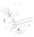
- the fastener system includes a fastener, comprising a bolt or threaded pin 12. a nut 14. and a tool 16.
- the pin 12 and nut 14 have a common axis 13.
- a pair of sheets 20. 22 comprising a workpiece are secured together by the fastener.
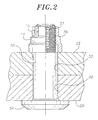
- the fastener secures the sheets together, forming a joint by compressive engagement between the nut 14 on one side of the workpiece, and a head 34 of the pin 12 on the opposite side, when the nut is torqued onto the pin.
- a cylindrical bore passes through the nut 14. and the inner surface (not shown) of the nut defining the bore is threaded.
- the nut 14 preferably has a plurality of external, axially extending lobes 15. of which one is shown, integrally formed on the nut.
- the internal thread of the nut 14 is adapted to receive the threaded pin 12.
- the pin 12 has a threaded portion 36. opposite the head 34.
- the threaded portion 36 preferably includes a plurality of flutes 37 having a generally concave curvature extending across the threads of the pin 12 in the axial direction.
- An end face 41 of the threaded end 36 of the pin includes a recess 39 for receiving the tool 16 to prevent rotation of the pin as the nut is torqued onto the pin by a driver 18 (illustrated in phantom in FIG. 1 ).
- the axial load applied between the bolt head and the nut increases up to a predetermined level. Once the predetermined axial load exists in the joint being made, the lobes 15 plastically deform into the flutes 37 of the pin to produce a mechanical thread lock.
- the number of flutes provided on the pin relative to the number of lobes provided on the nut is preferably such that some of the material of at least one of the lobes can enter one of the flutes to effect the mechanical thread lock.
- five flutes are provided in the pin with three lobes provided on the nut.
- Pin 12 includes a shank 30 that is received in aligned holes 32 in the workpiece.
- One end 36 of the shank is threaded for receiving the threads of the nut 14. and the other end of the shank has a head 34. which bears on an exposed surface of the workpiece to develop an axial load on the workpiece in cooperation with the nut.
- the head is arbitrarily illustrated without a wrenching surface, although other conventional pin heads may be used, such as hexagonal or countersunk heads.
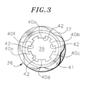
- recess 39 is provided in the end face 41 of the threaded end 36 of the pin to receive the tool 16. which holds the pin stationary while the driver turns to torque the nut.
- the recess 39 includes splines 40a-f equally spaced around the circumference of the recess.
- the splines may be formed in the pin by any suitable means, and are preferably machined into the end face of the threaded end of the pin.
- the recess 39 is contained entirely within the existing pin length of the fastener so that it is not necessary to add any material protruding from the end face 41 of the threaded end 36 of the pin.
- the depth of the recess is preferably such that a minimal amount of material will be removed from the lead-in or imperfect thread zone of the pin. For example a recess depth between .090 inch and .095 inch is acceptable.
- the recess 39 also referred to herein as a wrenching socket, includes the splines 40a-f having a geometry similar to wrenching sockets known as a "spline drive".
- the recess 39 has been substantially modified in order to balance the shear strength of the wrenching tool 16 with the shear strength of the fastener material.
- the wrenching socket 39 of the present invention has been designed to include spline widths and shear areas of both the socket and the wrenching tool to a level that closely approximates equably of torsional loading. This design increases the strength particularly when the fastener material possesses low strength.
- Another novel feature of the splines 40a-f is that the ends 42 of the splines are curved to accommodate a curved minor diameter 28 (See FIG. 4 ) of the wrenching tool 16.
- the tool 16 may be attached to a power tool for rapid installation of the fasteners, or may be used during hand installation of the fasteners.
- the tool 16 of which one embodiment is illustrated in FIGs. 1 and 4 .
- the tool comprises a solid, cylindrical shaft 24 with a plurality of splines 26 extending along the shaft. As seen best in FIG. 4 . six equally-spaced splines are located around the circumference of the shaft, parallel to the longitudinal axis 29 of the shaft. The splines preferably are all the same size.
- the splines 26 of the tool 16 are received within the matching splines 40a-f of the recess 39.
- the matching configurations of the tool and the recess engage one another to prevent the pin from rotating.
- the tool 16 includes a beveled edge 31 on a leading edge 33 of the tool to facilitate the insertion of the tool into the recess 39.
- the driving splines 26 are calculated to reduce the shear area so that it is in close balance strengthwise with the wrenching socket's shear area. The net result is a substantial increase in torsional performance, because the driving tool does not overpower the socket.
- the minor diameter 28 of the tool 16 has a curved surface.
- Prior spline driving tools included a minor diameter which was flat causing the loss of valuable torsional strength because material was removed to create the flat surface. By having a curved minor diameter, the torsional strength of the tool is increased due to the additional material.
- the spline width of the driving tool is less than the spline width of the socket. All of these design changes have improved the torsion values of the fastener. Improved torsional capability of the wrenching socket and the maximization of the torsional performance is particularly important when used in lower strength materials and minimum socket depth.
Landscapes
- Engineering & Computer Science (AREA)
- Mechanical Engineering (AREA)
- General Engineering & Computer Science (AREA)
- Details Of Spanners, Wrenches, And Screw Drivers And Accessories (AREA)
- Connection Of Plates (AREA)
- Insertion Pins And Rivets (AREA)
- Portable Nailing Machines And Staplers (AREA)
- Dowels (AREA)
Priority Applications (1)
| Application Number | Priority Date | Filing Date | Title |
|---|---|---|---|
| EP10185723.3A EP2275231B1 (en) | 1999-04-28 | 2000-04-25 | Fastener System with Spline Recess and Driving Tool |
Applications Claiming Priority (3)
| Application Number | Priority Date | Filing Date | Title |
|---|---|---|---|
| US301018 | 1999-04-28 | ||
| US09/301,018 US6237450B1 (en) | 1999-04-28 | 1999-04-28 | Fastener system with spline recess and driving tool |
| PCT/US2000/011117 WO2000064638A1 (en) | 1999-04-28 | 2000-04-25 | Fastener system with spline recess and driving tool |
Related Child Applications (2)
| Application Number | Title | Priority Date | Filing Date |
|---|---|---|---|
| EP10185723.3A Division EP2275231B1 (en) | 1999-04-28 | 2000-04-25 | Fastener System with Spline Recess and Driving Tool |
| EP10185723.3 Division-Into | 2010-10-01 |
Publications (3)
| Publication Number | Publication Date |
|---|---|
| EP1210212A1 EP1210212A1 (en) | 2002-06-05 |
| EP1210212A4 EP1210212A4 (en) | 2005-12-21 |
| EP1210212B1 true EP1210212B1 (en) | 2013-03-20 |
Family
ID=23161575
Family Applications (2)
| Application Number | Title | Priority Date | Filing Date |
|---|---|---|---|
| EP10185723.3A Expired - Lifetime EP2275231B1 (en) | 1999-04-28 | 2000-04-25 | Fastener System with Spline Recess and Driving Tool |
| EP00928379A Expired - Lifetime EP1210212B1 (en) | 1999-04-28 | 2000-04-25 | Fastener system with spline recess and driving tool |
Family Applications Before (1)
| Application Number | Title | Priority Date | Filing Date |
|---|---|---|---|
| EP10185723.3A Expired - Lifetime EP2275231B1 (en) | 1999-04-28 | 2000-04-25 | Fastener System with Spline Recess and Driving Tool |
Country Status (7)
| Country | Link |
|---|---|
| US (1) | US6237450B1 (ja) |
| EP (2) | EP2275231B1 (ja) |
| JP (2) | JP4094818B2 (ja) |
| AU (1) | AU4662800A (ja) |
| CA (1) | CA2371306C (ja) |
| ES (1) | ES2403237T3 (ja) |
| WO (1) | WO2000064638A1 (ja) |
Families Citing this family (8)
| Publication number | Priority date | Publication date | Assignee | Title |
|---|---|---|---|---|
| FR2802108B1 (fr) * | 1999-12-13 | 2002-03-01 | Salomon Sa | Dispositif de retenue d'une chaussure sur une planche de glisse |
| FR2822104B1 (fr) * | 2001-03-15 | 2003-06-13 | Vallourec Vitry | Fixation perfectionnee d'une traverse et de bras, notamment dabs un essieu semi-rigide |
| US6935209B2 (en) * | 2003-09-02 | 2005-08-30 | Alcoa Global Fasteners, Inc. | Key and key holder for fastener installation tool |
| KR101231254B1 (ko) * | 2011-06-22 | 2013-02-07 | 한국해양과학기술원 | 아지무스 추진기 |
| US9415470B2 (en) * | 2012-06-15 | 2016-08-16 | SprayRise Enterprise Partners, LLC | Apparatus and system for removing, replacing and/or reinstalling sprinkler heads |
| WO2015050942A1 (en) | 2013-10-01 | 2015-04-09 | Alcoa Inc. | Asymmetric fastener recess and key |
| US10562159B2 (en) * | 2018-01-30 | 2020-02-18 | General Electric Company | Bolt tightening system |
| CN110193805B (zh) * | 2019-06-28 | 2024-01-30 | 江苏金梧实业股份有限公司 | 压紧式安全销座总成 |
Family Cites Families (22)
| Publication number | Priority date | Publication date | Assignee | Title |
|---|---|---|---|---|
| US1075710A (en) * | 1911-01-07 | 1913-10-14 | Oscar S Fitzsimons | Set-screw or the like. |
| GB548653A (en) * | 1941-12-02 | 1942-10-19 | Cosby Donald Philipps Smallpei | Improvements relating to bolts and the like |
| GB833128A (en) * | 1958-01-24 | 1960-04-21 | Socketex Ltd | Tee bolts and studs |
| US3285119A (en) * | 1964-05-05 | 1966-11-15 | Hi Shear Corp | Torque-limiting fastener |
| US3584667A (en) * | 1966-09-19 | 1971-06-15 | Textron Inc | Coupling arrangement and tools for same |
| US3700992A (en) * | 1971-07-26 | 1972-10-24 | Coulter Electronics | Curve tracer |
| US4260005A (en) | 1977-11-09 | 1981-04-07 | Vsi Corporation | Self-locking fastener, fastener system, and process |
| JPS58144113U (ja) * | 1982-03-24 | 1983-09-28 | 株式会社三之橋製作所 | 片側締めボルト |
| US4583483A (en) | 1982-09-30 | 1986-04-22 | Honeywell Inc. | Mechanical meter tampering indicator |
| DE3481211D1 (de) * | 1983-10-14 | 1990-03-08 | Alfons Knoche | Universalschraube. |
| US4809569A (en) * | 1987-12-30 | 1989-03-07 | Erb John C | Anti-theft system for articles secured by recessed socket head threaded fasteners |
| US5044225A (en) | 1990-06-21 | 1991-09-03 | Vsi Corporation | Pneumatic nut installation tool |
| US5088869A (en) * | 1991-01-24 | 1992-02-18 | Greenslade Joe E | Thread rolling screw |
| IT1245285B (it) * | 1991-03-20 | 1994-09-13 | Fossati Onorina | Vite per serraggi di precisione e chiave di manovra per tale vite |
| DE4124472A1 (de) * | 1991-07-24 | 1993-01-28 | Wuerth Adolf Gmbh & Co Kg | Schraube |
| US5207132A (en) * | 1991-10-16 | 1993-05-04 | Textron Inc. | Elliptical lobed drive system |
| JPH0737805B2 (ja) * | 1992-11-17 | 1995-04-26 | 有限会社新城製作所 | 凹部付きねじ及びそのドライバビット |
| JPH06185511A (ja) * | 1992-12-18 | 1994-07-05 | O S G Kk | 片側締めボルト |
| JPH08135634A (ja) * | 1994-11-09 | 1996-05-31 | Kunitaka Takemae | ボルトおよび該ボルトを利用して電話ボックスの台板上へ固定した公衆電話機 |
| US5549431A (en) * | 1995-01-03 | 1996-08-27 | Royle; Ian A. | Tube screw fastener |
| US5699702A (en) * | 1996-08-01 | 1997-12-23 | Fairchild Holding Corp. | Wrenching tool with free-floating, self-relieving anti-rotation key |
| EP0947716A3 (en) * | 1998-04-03 | 2000-08-23 | Fairchild Holding Corp. | Fastener system with cross-slot recess and cross-slot bit |
-
1999
- 1999-04-28 US US09/301,018 patent/US6237450B1/en not_active Expired - Lifetime
-
2000
- 2000-04-25 EP EP10185723.3A patent/EP2275231B1/en not_active Expired - Lifetime
- 2000-04-25 CA CA002371306A patent/CA2371306C/en not_active Expired - Lifetime
- 2000-04-25 EP EP00928379A patent/EP1210212B1/en not_active Expired - Lifetime
- 2000-04-25 ES ES00928379T patent/ES2403237T3/es not_active Expired - Lifetime
- 2000-04-25 AU AU46628/00A patent/AU4662800A/en not_active Abandoned
- 2000-04-25 JP JP2000613615A patent/JP4094818B2/ja not_active Expired - Lifetime
- 2000-04-25 WO PCT/US2000/011117 patent/WO2000064638A1/en active Application Filing
-
2004
- 2004-09-15 JP JP2004268506A patent/JP4773075B2/ja not_active Expired - Lifetime
Also Published As
| Publication number | Publication date |
|---|---|
| CA2371306A1 (en) | 2000-11-02 |
| JP2002542059A (ja) | 2002-12-10 |
| JP4773075B2 (ja) | 2011-09-14 |
| WO2000064638A1 (en) | 2000-11-02 |
| EP2275231A3 (en) | 2011-04-20 |
| EP1210212A1 (en) | 2002-06-05 |
| ES2403237T3 (es) | 2013-05-16 |
| EP2275231B1 (en) | 2019-03-27 |
| JP2005042925A (ja) | 2005-02-17 |
| EP1210212A4 (en) | 2005-12-21 |
| CA2371306C (en) | 2005-01-18 |
| JP4094818B2 (ja) | 2008-06-04 |
| EP2275231A2 (en) | 2011-01-19 |
| AU4662800A (en) | 2000-11-10 |
| US6237450B1 (en) | 2001-05-29 |
Similar Documents
| Publication | Publication Date | Title |
|---|---|---|
| US5108238A (en) | Torque limiting bolt for power wrench tightening | |
| EP1635994B1 (en) | Blind fastener and nose assembly for installation of the blind fastener | |
| US5984022A (en) | Automatic shaft lock | |
| EP2753835B1 (en) | Negative drive angle | |
| US5544991A (en) | Locking frustrum nut | |
| US6810571B1 (en) | Method of tightening and loosening an object | |
| US4682520A (en) | Mechanically lockable fastener assembly | |
| US6454502B1 (en) | Blind fastener and drive nut assembly | |
| US5390573A (en) | Fastening system for torque limited fasteners | |
| US6213698B1 (en) | Structural blind bolt | |
| US20040022596A1 (en) | Fastener having integral drive nut | |
| US4742735A (en) | Driver for a lobed collar | |
| EP1210212B1 (en) | Fastener system with spline recess and driving tool | |
| EP0477517B1 (en) | Self-locking fastener | |
| JPS6283507A (ja) | 盲締め具並びにその締結方法 | |
| EP0947716A2 (en) | Fastener system with cross-slot recess and cross-slot bit | |
| GB2112488A (en) | Improvements in or relating to threaded fastener and nut assemblies and mounting tools therefor | |
| GB2146724A (en) | Torque-limited screw-thread locking fastener | |
| GB2111886A (en) | Screwdriver | |
| US20020164203A1 (en) | Method of fastening panels using blind fasteners with engageable drive nuts | |
| CA1234303A (en) | Torque-limited threaded locking fastener, and method for setting the same | |
| JPH038403B2 (ja) |
Legal Events
| Date | Code | Title | Description |
|---|---|---|---|
| PUAI | Public reference made under article 153(3) epc to a published international application that has entered the european phase |
Free format text: ORIGINAL CODE: 0009012 |
|
| 17P | Request for examination filed |
Effective date: 20011025 |
|
| AK | Designated contracting states |
Kind code of ref document: A1 Designated state(s): AT BE CH CY DE DK ES FI FR GB GR IE IT LI LU MC NL PT SE |
|
| AX | Request for extension of the european patent |
Free format text: AL;LT;LV;MK;RO;SI |
|
| RAP1 | Party data changed (applicant data changed or rights of an application transferred) |
Owner name: HUCK PATENTS, INC. |
|
| RBV | Designated contracting states (corrected) |
Designated state(s): DE ES FR GB IT |
|
| A4 | Supplementary search report drawn up and despatched |
Effective date: 20051107 |
|
| REG | Reference to a national code |
Ref country code: DE Ref legal event code: R079 Ref document number: 60047890 Country of ref document: DE Free format text: PREVIOUS MAIN CLASS: B25B0023000000 Ipc: B25B0015000000 |
|
| GRAP | Despatch of communication of intention to grant a patent |
Free format text: ORIGINAL CODE: EPIDOSNIGR1 |
|
| RIC1 | Information provided on ipc code assigned before grant |
Ipc: B25B 15/00 20060101AFI20120911BHEP |
|
| GRAS | Grant fee paid |
Free format text: ORIGINAL CODE: EPIDOSNIGR3 |
|
| GRAA | (expected) grant |
Free format text: ORIGINAL CODE: 0009210 |
|
| AK | Designated contracting states |
Kind code of ref document: B1 Designated state(s): DE ES FR GB IT |
|
| REG | Reference to a national code |
Ref country code: GB Ref legal event code: FG4D |
|
| REG | Reference to a national code |
Ref country code: DE Ref legal event code: R096 Ref document number: 60047890 Country of ref document: DE Effective date: 20130516 Ref country code: ES Ref legal event code: FG2A Ref document number: 2403237 Country of ref document: ES Kind code of ref document: T3 Effective date: 20130516 |
|
| PLBE | No opposition filed within time limit |
Free format text: ORIGINAL CODE: 0009261 |
|
| STAA | Information on the status of an ep patent application or granted ep patent |
Free format text: STATUS: NO OPPOSITION FILED WITHIN TIME LIMIT |
|
| 26N | No opposition filed |
Effective date: 20140102 |
|
| PG25 | Lapsed in a contracting state [announced via postgrant information from national office to epo] |
Ref country code: IT Free format text: LAPSE BECAUSE OF FAILURE TO SUBMIT A TRANSLATION OF THE DESCRIPTION OR TO PAY THE FEE WITHIN THE PRESCRIBED TIME-LIMIT Effective date: 20130320 |
|
| REG | Reference to a national code |
Ref country code: DE Ref legal event code: R097 Ref document number: 60047890 Country of ref document: DE Effective date: 20140102 |
|
| REG | Reference to a national code |
Ref country code: FR Ref legal event code: PLFP Year of fee payment: 17 |
|
| REG | Reference to a national code |
Ref country code: FR Ref legal event code: PLFP Year of fee payment: 18 |
|
| REG | Reference to a national code |
Ref country code: FR Ref legal event code: PLFP Year of fee payment: 19 |
|
| PGFP | Annual fee paid to national office [announced via postgrant information from national office to epo] |
Ref country code: GB Payment date: 20190325 Year of fee payment: 20 Ref country code: FR Payment date: 20190325 Year of fee payment: 20 |
|
| PGFP | Annual fee paid to national office [announced via postgrant information from national office to epo] |
Ref country code: ES Payment date: 20190502 Year of fee payment: 20 Ref country code: DE Payment date: 20190220 Year of fee payment: 20 |
|
| REG | Reference to a national code |
Ref country code: DE Ref legal event code: R071 Ref document number: 60047890 Country of ref document: DE |
|
| REG | Reference to a national code |
Ref country code: GB Ref legal event code: PE20 Expiry date: 20200424 |
|
| PG25 | Lapsed in a contracting state [announced via postgrant information from national office to epo] |
Ref country code: GB Free format text: LAPSE BECAUSE OF EXPIRATION OF PROTECTION Effective date: 20200424 |
|
| REG | Reference to a national code |
Ref country code: ES Ref legal event code: FD2A Effective date: 20201203 |
|
| PG25 | Lapsed in a contracting state [announced via postgrant information from national office to epo] |
Ref country code: ES Free format text: LAPSE BECAUSE OF EXPIRATION OF PROTECTION Effective date: 20200426 |