EP1209636A2 - Self-service terminal - Google Patents
Self-service terminal Download PDFInfo
- Publication number
- EP1209636A2 EP1209636A2 EP01307917A EP01307917A EP1209636A2 EP 1209636 A2 EP1209636 A2 EP 1209636A2 EP 01307917 A EP01307917 A EP 01307917A EP 01307917 A EP01307917 A EP 01307917A EP 1209636 A2 EP1209636 A2 EP 1209636A2
- Authority
- EP
- European Patent Office
- Prior art keywords
- user
- user interface
- informing
- interface element
- controller
- Prior art date
- Legal status (The legal status is an assumption and is not a legal conclusion. Google has not performed a legal analysis and makes no representation as to the accuracy of the status listed.)
- Withdrawn
Links
Images


Classifications
-
- G—PHYSICS
- G07—CHECKING-DEVICES
- G07F—COIN-FREED OR LIKE APPARATUS
- G07F19/00—Complete banking systems; Coded card-freed arrangements adapted for dispensing or receiving monies or the like and posting such transactions to existing accounts, e.g. automatic teller machines
- G07F19/20—Automatic teller machines [ATMs]
-
- G—PHYSICS
- G06—COMPUTING OR CALCULATING; COUNTING
- G06Q—INFORMATION AND COMMUNICATION TECHNOLOGY [ICT] SPECIALLY ADAPTED FOR ADMINISTRATIVE, COMMERCIAL, FINANCIAL, MANAGERIAL OR SUPERVISORY PURPOSES; SYSTEMS OR METHODS SPECIALLY ADAPTED FOR ADMINISTRATIVE, COMMERCIAL, FINANCIAL, MANAGERIAL OR SUPERVISORY PURPOSES, NOT OTHERWISE PROVIDED FOR
- G06Q20/00—Payment architectures, schemes or protocols
- G06Q20/08—Payment architectures
- G06Q20/10—Payment architectures specially adapted for electronic funds transfer [EFT] systems; specially adapted for home banking systems
- G06Q20/108—Remote banking, e.g. home banking
- G06Q20/1085—Remote banking, e.g. home banking involving automatic teller machines [ATMs]
-
- G—PHYSICS
- G07—CHECKING-DEVICES
- G07F—COIN-FREED OR LIKE APPARATUS
- G07F19/00—Complete banking systems; Coded card-freed arrangements adapted for dispensing or receiving monies or the like and posting such transactions to existing accounts, e.g. automatic teller machines
- G07F19/20—Automatic teller machines [ATMs]
- G07F19/201—Accessories of ATMs
-
- G—PHYSICS
- G09—EDUCATION; CRYPTOGRAPHY; DISPLAY; ADVERTISING; SEALS
- G09B—EDUCATIONAL OR DEMONSTRATION APPLIANCES; APPLIANCES FOR TEACHING, OR COMMUNICATING WITH, THE BLIND, DEAF OR MUTE; MODELS; PLANETARIA; GLOBES; MAPS; DIAGRAMS
- G09B21/00—Teaching, or communicating with, the blind, deaf or mute
- G09B21/001—Teaching or communicating with blind persons
Definitions
- the present invention relates to a self-service terminal (SST) having an improved user interface.
- the invention relates to an automated teller machine (ATM).
- User interfaces on self-service terminals such as ATMs are designed to allow users to enter complex transactions in a simple manner.
- user interfaces are typically designed for people who have relatively good eyesight: users who are visually impaired have difficulty using ATMs because it is difficult for them to determine which user interface element (for example, the keypad, card reader, printer slot, and such like) is being used, and where that element is located on the user interface.
- user interface element for example, the keypad, card reader, printer slot, and such like
- the physical space occupied by the user interface increases; this makes it even more difficult for visually impaired users to locate a particular user interface element to interact with.
- a self-service terminal having a user interface comprising a plurality of user interface elements, characterised in that at least one user interface element has means for detecting a user's hand in the vicinity of that element, and means for informing the user about that element.
- the informing means may describe a user interface element by reference to a type of module.
- the module may be that user interface element (for example, a keypad, a display, and such like); or may be a module associated with that user interface element (for example, a card reader module is associated with a card entry/exit slot, a receipt printer is associated with a receipt slot).
- the detecting means may detect a user's finger in the vicinity of a sub-element, and the informing means may inform the user about a function performed by that sub-element (for example, the detecting means may detect a user's finger in the vicinity of the "1" key, the "Cancel” key, the "Enter” key, or some other key on the keypad).
- the informing means may not inform the user about the function of a sub-element if there is a risk in disclosing a user's personal data; for example, if a user intends to enter a personal identification number (PIN), the informing means may not inform the user, or may only inform the user about one numeral key so that the user is assisted in navigating the keypad but the user's PIN is not disclosed to passers-by.
- PIN personal identification number
- the detecting means comprises a proximity sensor.
- the detecting means may comprise an emitter and detector arrangement for detecting emissions from the emitter that have been reflected by the user's hand.
- Proximity sensors are well known, and will not be described in detail herein. Examples of sensors suitable for use in the present invention are available from Pepperl and Fuchs, Postfach 31 04 40, D-6800, Mannheim 31, Germany. Conveniently, the proximity sensor is a capacitive sensor, or alternatively may be an inductive sensor.
- the informing means comprises a loudspeaker actuated by a controller.
- the controller may include pre-recorded sound files or clips that are played through the loudspeaker.
- the controller may include a text to speech program and text files associated with the user interface elements.
- the informing means comprises a controller for displaying large text on a display.
- the controller used in the informing means also controls the operation of the terminal.
- a user is able to move his/her hand to the vicinity of a user interface element, and be informed about the function of that element.
- a user is able to determine the layout of a terminal by moving his/her hand slowly over the user interface of that terminal.
- an element has sub-elements that change function during a transaction (for example, an FDK may change function depending on a previous selection by the user) the user may discover the current function provided by that sub-element by moving his/her hand to the vicinity of the sub-element.
- an FDK may change function depending on a previous selection by the user
- a method of informing a user of a self-service terminal about a user interface element included in that terminal comprising the steps of:
- the informing step may include the sub-steps of:
- the audio file may be played through a loudspeaker or audio jack.
- the audio jack has the advantage of increased privacy, which is particularly important when financial transactions are being executed at a public access terminal such as an ATM.
- a user may have to touch a user interface element before the informing means informs the user about the function of that element.
- the ATM 10 comprises a chassis (not shown) for supporting a fascia 12, exterior panels 14 and internal ATM modules (not shown in Fig 1).
- the fascia 12 includes a user interface 16 incorporating a plurality of user interface elements in the form of modules and slots. When the fascia 12 engages fully with the chassis and panels 14 the slots align with ATM modules located within the ATM 10.
- the user interface 16 comprises the following user interface elements: a display 18, a cash dispense slot 20, a card entry/exit slot 22 (herein referred to as a card entry slot), a receipt slot 24, an encrypting keypad 26, a function display key module (FDKs) 28 associated with the display 18, and a loudspeaker 29.
- a display 18 a cash dispense slot 20
- a card entry/exit slot 22 herein referred to as a card entry slot
- FDKs function display key module
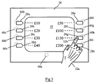
- the FDK module user interface element 28 comprises eight FDK sub-elements, labelled 28a to 28h (for clarity, only FDKs 28a to 28d are shown in Fig 1).
- the fascia 12 has a lock mechanism 30 for securing the fascia 12 to and for releasing the fascia 12 from the chassis and panels 14.
- Fig 2 illustrates a user (customer) 32 operating the ATM 10, and also illustrates the ATM internal modules in block diagram form.
- the ATM 10 includes the following internal modules: a magnetic card reader/writer (MCRW) module 34 that aligns with the card entry slot 22, a printer module 36 that aligns with the receipt slot 24, an internal journal printer module 38, a cash dispenser module 40 that aligns with the cash dispense slot 20, an ATM controller module 42 for controlling the operation of the various modules, and a network connection module 44 for communicating with a remote transaction host (not shown). All of the modules within the ATM 12 are interconnected by an internal bus 46 for securely conveying data.
- MCRW magnetic card reader/writer
- the display 18 may be considered as an internal ATM module because it is mounted within the ATM and is not coupled to the fascia 12, it has been described herein as part of the user interface 16 on the fascia 12 because the display 18 protrudes through a large aperture in the fascia 12 so that it appears as part of the fascia 12.
- the ATM controller 42 includes a processor 48 and associated memory 50, and executes an ATM control program 52.
- the control program 52 includes sound files (not shown), each file containing a spoken description of a user interface element (for example, "card reader slot", "display") or the function of a sub-element (for example, "withdraw ten pounds").
- the ATM 10 also includes means for detecting a user's hand in the vicinity of a user interface element in the form of a plurality of proximity sensors 60 located behind the fascia 12.
- Each sensor 60 is a capacitive proximity sensor, of the type available from Pepperl and Fuchs, Postfach 31 04 40, D-6800, Mannheim 31, Germany, and is located adjacent or within a user interface element or sub-element.
- Sensor 60a is located adjacent the display 18; each of sensors 60b to 60i is located adjacent a respective one of the eight FDKs 28a to 28h in FDK module 28; sensor 60j is located adjacent keypad 26; sensor 60k is located adjacent card entry slot 22; sensor 601 is located adjacent printer slot 24; and sensor 60m is located adjacent cash dispense slot 20.
- Each sensor 60 is coupled to the ATM controller module 42 so that the ATM controller 42 can determine which sensor 60 detects proximity of a user's hand, thereby enabling the ATM controller 42 to determine the approximate position of the user's hand.
- Fig 3 is a block diagram of the FDK module 28 overlying the display 18.
- a visually impaired user 32 approaches the ATM 14, and locates the card entry slot 22 by moving his hand 32a, and particularly his finger 32b, slowly across the fascia 12.
- the sensor 601 detects the user's finger 32b and sends a signal to the ATM controller 42.
- the ATM controller 42 receives this signal, and the ATM control program 52 determines which sensor 601 detected the user's finger 32b, selects an audio file associated with that sensor 601 (in this example a receipt slot file), and plays the file through the loudspeaker 29.
- the user 32 hears the audio file which has a person saying "Receipt slot".
- the user knows that his hand 32a is adjacent the receipt slot 24.
- the user 32 can then move his finger upwards to locate the card entry slot 22.
- the user's finger 32b is adjacent the card entry slot sensor 60k, then the user hears the words "Card reader slot” through loudspeaker 29 because the ATM control program 52 has detected sensor 60k being active and has selected the audio file for the card reader slot 22.
- the user 32 then enters his card into slot 22, and locates the keypad 26 by moving his finger back across the fascia 12.
- the user 32 can deduce the layout of the keypad 26 because the numeric keys are located in a standard arrangement, the top left corner of the keypad having the numeral "1".
- the display 18 presents a screen to the user 32 providing the user with transaction options to select using an FDK 28a to 28h.
- screen is used herein to denote the graphics, text, controls (such as menu options), and such like, that are presented on the display; the term “screen” as used herein does not refer to the hardware (that is, the display) that presents the graphics, text, controls, and such like.
- the user can locate the FDK module 28 by moving his hand upwards until his finger 32b is in the vicinity of one of the FDK sensors 60b to 60i.
- Each FDK 28a to 28h has an associated audio file for each stage in a transaction.
- the ATM control program 52 determines what screen is being presented by the display 18, so that the program 52 can select the appropriate audio file for playing to the user
- the user 32 continues entering the transaction until the transaction has been completed. The user 32 then removes his card and any cash and/or receipt he has requested before leaving the ATM 10.
- the above embodiment has the advantage that a user is able to obtain information about a user interface element (such as the card reader slot) or sub-element (such as a particular FDK in the FDK module) during a transaction, thereby improving usability for a visually impaired user.
- a user interface element such as the card reader slot
- sub-element such as a particular FDK in the FDK module
- a sensor 60 may be indirectly coupled to the ATM controller 42 (for example, via a module associated with that sensor); or coupled (directly or indirectly) to a dedicated controller.
- the user interface 16 may include a jack for receiving headphones so that the user can privately listen to any instructions from the ATM 10.
- the keypad 26 may include sensors adjacent one or more of the numeral keys.
- the keypad may have a sensor adjacent the enter key and a sensor adjacent the cancel key, so that once a user has entered his/her PIN, he/she can determine what key to press to proceed with a transaction.
- a keyboard or keypad may be provided that has sensors adjacent each key.
- This keypad may be used to provide the functions of an FDK module so that a user can use the keypad to select functions that vary depending on the transaction being executed and/or the stage of the transaction.
- the keyboard or keypad may be non-secure (for example, not used for entering a PIN).
- a keypad may be provided, whereby the terminal allows a user to depress a key once, and in response to the single press to inform the user about the function performed by that key, and in response to a double press, or to a second press of the same key shortly after the first press, to perform that function.
- the terminal may be a non-cash kiosk.
Landscapes
- Business, Economics & Management (AREA)
- Accounting & Taxation (AREA)
- Finance (AREA)
- General Physics & Mathematics (AREA)
- Physics & Mathematics (AREA)
- Engineering & Computer Science (AREA)
- Theoretical Computer Science (AREA)
- General Health & Medical Sciences (AREA)
- Health & Medical Sciences (AREA)
- Educational Technology (AREA)
- Educational Administration (AREA)
- Audiology, Speech & Language Pathology (AREA)
- Development Economics (AREA)
- Economics (AREA)
- Strategic Management (AREA)
- General Business, Economics & Management (AREA)
- User Interface Of Digital Computer (AREA)
- Telephone Function (AREA)
- Financial Or Insurance-Related Operations Such As Payment And Settlement (AREA)
Abstract
Description
Claims (10)
- A self-service terminal (10) having a user interface (16) comprising a plurality of user interface elements (18,20,22,24,26,28,29), characterised in that at least one user interface element has means (60) for detecting a user's hand in the vicinity of that element, and means (42,29) for informing the user about that element.
- A terminal according to claim 1, wherein the informing means (42,29) describes a user interface element by reference to a type of module.
- A terminal according to claim 1 or claim 2, wherein the detecting means (60) comprises a proximity sensor.
- A terminal according to claim 1 or claim 2, wherein the detecting means (60) requires a user to touch a user interface element.
- A terminal according to any preceding claim, wherein the informing means (42,29) comprises a loudspeaker (29) actuated by a controller (42).
- A terminal according to claim 5, wherein the controller (42) includes pre-recorded sound files that are played through the loudspeaker (29).
- A terminal according to claim 5, wherein the controller (42) includes a text to speech program and text files associated with the user interface elements.
- A terminal according to any of claims 5 to 7, wherein the informing means (42,29) comprises a controller for displaying large text on a display (18).
- A method of informing a user of a self-service terminal about a user interface element included in that terminal, the method comprising the steps of: detecting a user's hand in the vicinity of a user interface element; and informing the user about that user interface element.
- A method according to claim 9, wherein the informing step includes the sub-steps of: detecting which user interface element the user's hand is in the vicinity of; selecting an audio file associated with that element; and playing the audio file.
Applications Claiming Priority (2)
| Application Number | Priority Date | Filing Date | Title |
|---|---|---|---|
| GBGB0028712.8A GB0028712D0 (en) | 2000-11-24 | 2000-11-24 | Self-service terminal |
| GB0028712 | 2000-11-24 |
Publications (2)
| Publication Number | Publication Date |
|---|---|
| EP1209636A2 true EP1209636A2 (en) | 2002-05-29 |
| EP1209636A3 EP1209636A3 (en) | 2005-03-09 |
Family
ID=9903832
Family Applications (1)
| Application Number | Title | Priority Date | Filing Date |
|---|---|---|---|
| EP01307917A Withdrawn EP1209636A3 (en) | 2000-11-24 | 2001-09-18 | Self-service terminal |
Country Status (3)
| Country | Link |
|---|---|
| US (1) | US20020073032A1 (en) |
| EP (1) | EP1209636A3 (en) |
| GB (1) | GB0028712D0 (en) |
Cited By (2)
| Publication number | Priority date | Publication date | Assignee | Title |
|---|---|---|---|---|
| EP1672580A1 (en) * | 2004-12-17 | 2006-06-21 | Ncr International Inc. | An automated teller machine |
| DE102005014774A1 (en) * | 2005-03-31 | 2006-10-05 | Siemens Ag | Procedure for input preview and user interface with input preview |
Families Citing this family (22)
| Publication number | Priority date | Publication date | Assignee | Title |
|---|---|---|---|---|
| US20030217005A1 (en) * | 1996-11-27 | 2003-11-20 | Diebold Self Service Systems, Division Of Diebold, Incorporated | Automated banking machine system and method |
| US6856006B2 (en) * | 2002-03-28 | 2005-02-15 | Siliconix Taiwan Ltd | Encapsulation method and leadframe for leadless semiconductor packages |
| WO2003021545A1 (en) * | 2001-08-30 | 2003-03-13 | Fujitsu Limited | Automatic money transacting apparatus, and paper currency unit having built-in camera |
| US7270264B2 (en) * | 2003-03-10 | 2007-09-18 | Diebold Self-Service Systems, Division Of Diebold, Incorporated | Cash dispensing automated banking machine with interlocking sheet metal parts |
| US20070215686A1 (en) * | 2004-01-22 | 2007-09-20 | Matson Craig E | Automated teller machine voice guidance system and method |
| US7494050B1 (en) * | 2004-06-29 | 2009-02-24 | Diebold Self-Service Systems Division Of Diebold, Incorporated | Automated banking machine audible user interface method |
| US9093359B2 (en) * | 2005-07-01 | 2015-07-28 | Vishay-Siliconix | Complete power management system implemented in a single surface mount package |
| US7494053B1 (en) * | 2005-11-14 | 2009-02-24 | Diebold Self-Service Systems Division Of Diebold, Incorporated | Cash dispensing automated banking machine and method |
| US7774851B2 (en) * | 2005-12-22 | 2010-08-10 | Scenera Technologies, Llc | Methods, systems, and computer program products for protecting information on a user interface based on a viewability of the information |
| US20070282783A1 (en) * | 2006-05-31 | 2007-12-06 | Mona Singh | Automatically determining a sensitivity level of a resource and applying presentation attributes to the resource based on attributes of a user environment |
| US20080136657A1 (en) * | 2006-12-08 | 2008-06-12 | Barrie Clark | Automated teller machine |
| US8127981B1 (en) * | 2007-09-07 | 2012-03-06 | Diebold Self-Service Systems Division Of Diebold, Incorporated | Banking system controlled responsive to data bearing records |
| US20100042236A1 (en) * | 2008-08-15 | 2010-02-18 | Ncr Corporation | Self-service terminal |
| GB0909277D0 (en) | 2009-05-29 | 2009-07-15 | Design Multimedia Ltd I | A control system and method for a user terminal |
| US10152615B2 (en) * | 2011-05-03 | 2018-12-11 | Ncr Corporation | Fraud prevention |
| KR102157733B1 (en) * | 2013-07-15 | 2020-09-18 | 효성티앤에스 주식회사 | ATM with EPP guard cave |
| JP6438854B2 (en) * | 2015-06-26 | 2018-12-19 | 日立オムロンターミナルソリューションズ株式会社 | Automatic transaction device, automatic transaction method |
| USD812657S1 (en) * | 2016-04-12 | 2018-03-13 | Netzsch-Feinmahltechnik Gmbh | Agitator bead mill |
| US10255738B1 (en) | 2016-07-25 | 2019-04-09 | United Services Automobile Association (Usaa) | Authentication based on through-body signals detected in body area networks |
| US10769896B1 (en) * | 2019-05-01 | 2020-09-08 | Capital One Services, Llc | Counter-fraud measures for an ATM device |
| FR3144882B1 (en) * | 2023-01-05 | 2025-06-20 | Systemes Et Tech Identification Stid | Code entry system with activation of a mode adapted for visually impaired people |
| FR3144879B1 (en) * | 2023-01-05 | 2025-04-18 | Systemes Et Tech Identification Stid | Code entry system on a touchscreen keyboard suitable for visually impaired people |
Family Cites Families (7)
| Publication number | Priority date | Publication date | Assignee | Title |
|---|---|---|---|---|
| US531175A (en) * | 1894-12-18 | Ed ward e | ||
| JP2857777B2 (en) * | 1989-10-26 | 1999-02-17 | 株式会社日立製作所 | Automatic teller machine |
| US5311175A (en) * | 1990-11-01 | 1994-05-10 | Herbert Waldman | Method and apparatus for pre-identification of keys and switches |
| EP0516228B1 (en) * | 1991-05-31 | 1999-12-15 | Koninklijke Philips Electronics N.V. | Device with a human-machine interface |
| US5616901A (en) * | 1995-12-19 | 1997-04-01 | Talking Signs, Inc. | Accessible automatic teller machines for sight-impaired persons and print-disabled persons |
| US6061666A (en) * | 1996-12-17 | 2000-05-09 | Citicorp Development Center | Automatic bank teller machine for the blind and visually impaired |
| US6761308B1 (en) * | 1998-11-25 | 2004-07-13 | Diebold, Incorporated | Automated merchant banking apparatus and method |
-
2000
- 2000-11-24 GB GBGB0028712.8A patent/GB0028712D0/en not_active Ceased
-
2001
- 2001-09-18 EP EP01307917A patent/EP1209636A3/en not_active Withdrawn
- 2001-10-23 US US10/004,133 patent/US20020073032A1/en not_active Abandoned
Cited By (3)
| Publication number | Priority date | Publication date | Assignee | Title |
|---|---|---|---|---|
| EP1672580A1 (en) * | 2004-12-17 | 2006-06-21 | Ncr International Inc. | An automated teller machine |
| US7575166B2 (en) | 2004-12-17 | 2009-08-18 | Ncr Corporation | Automated teller machine |
| DE102005014774A1 (en) * | 2005-03-31 | 2006-10-05 | Siemens Ag | Procedure for input preview and user interface with input preview |
Also Published As
| Publication number | Publication date |
|---|---|
| GB0028712D0 (en) | 2001-01-10 |
| EP1209636A3 (en) | 2005-03-09 |
| US20020073032A1 (en) | 2002-06-13 |
Similar Documents
| Publication | Publication Date | Title |
|---|---|---|
| US20020073032A1 (en) | Self-service terminal | |
| US6474547B1 (en) | Automatic service equipment | |
| US7575166B2 (en) | Automated teller machine | |
| US5610382A (en) | Automatic cash transaction apparatus having a main body and an additional unit | |
| EP0965961A1 (en) | Self service terminal display screen | |
| US6630941B1 (en) | Self-service terminal | |
| JPH10149258A (en) | Input operation device | |
| JP6060521B2 (en) | Transaction apparatus and transaction program | |
| US20030132287A1 (en) | Kiosk having a people presence detector to determine if a kiosk item is to be presented to a customer | |
| JPH1185438A (en) | Automatic transaction operation device | |
| JPH09223250A (en) | Terminal device | |
| JP3718270B2 (en) | Self-service transaction terminal | |
| JP3802618B2 (en) | Automatic device input method and automatic device | |
| KR100542020B1 (en) | Front and rear screen switching method and effective screen switching device | |
| JP2000259893A (en) | Automatic teller machine | |
| EP0884703A2 (en) | Method of processing a financial transaction and a self-service banking system therefor | |
| JP2008242546A (en) | Information processing device | |
| CN119213399A (en) | Self-service terminal and method | |
| JPH11110107A (en) | Information input device and automatic transaction device | |
| JP4577955B2 (en) | Automatic cash transaction equipment | |
| JP2806419B2 (en) | Operation display method and operation display mechanism of automatic transaction device | |
| US6581024B1 (en) | Consumer transaction facility | |
| JPH08329315A (en) | Guidance control method | |
| JP6904663B2 (en) | ATM | |
| JP2006338403A (en) | Automatic transaction device |
Legal Events
| Date | Code | Title | Description |
|---|---|---|---|
| PUAI | Public reference made under article 153(3) epc to a published international application that has entered the european phase |
Free format text: ORIGINAL CODE: 0009012 |
|
| AK | Designated contracting states |
Kind code of ref document: A2 Designated state(s): AT BE CH CY DE DK ES FI FR GB GR IE IT LI LU MC NL PT SE TR |
|
| AX | Request for extension of the european patent |
Free format text: AL;LT;LV;MK;RO;SI |
|
| PUAL | Search report despatched |
Free format text: ORIGINAL CODE: 0009013 |
|
| AK | Designated contracting states |
Kind code of ref document: A3 Designated state(s): AT BE CH CY DE DK ES FI FR GB GR IE IT LI LU MC NL PT SE TR |
|
| AX | Request for extension of the european patent |
Extension state: AL LT LV MK RO SI |
|
| RIC1 | Information provided on ipc code assigned before grant |
Ipc: 7G 06F 3/00 B Ipc: 7G 09B 21/00 B Ipc: 7G 07F 19/00 A |
|
| 17P | Request for examination filed |
Effective date: 20050909 |
|
| AKX | Designation fees paid |
Designated state(s): DE ES FR GB IT |
|
| STAA | Information on the status of an ep patent application or granted ep patent |
Free format text: STATUS: THE APPLICATION IS DEEMED TO BE WITHDRAWN |
|
| 18D | Application deemed to be withdrawn |
Effective date: 20060707 |