EP1209552B1 - Information processing device - Google Patents
Information processing device Download PDFInfo
- Publication number
- EP1209552B1 EP1209552B1 EP01926147.8A EP01926147A EP1209552B1 EP 1209552 B1 EP1209552 B1 EP 1209552B1 EP 01926147 A EP01926147 A EP 01926147A EP 1209552 B1 EP1209552 B1 EP 1209552B1
- Authority
- EP
- European Patent Office
- Prior art keywords
- display unit
- disposed
- antenna member
- antenna
- information processing
- Prior art date
- Legal status (The legal status is an assumption and is not a legal conclusion. Google has not performed a legal analysis and makes no representation as to the accuracy of the status listed.)
- Expired - Lifetime
Links
Images


Classifications
-
- H—ELECTRICITY
- H01—ELECTRIC ELEMENTS
- H01Q—ANTENNAS, i.e. RADIO AERIALS
- H01Q1/00—Details of, or arrangements associated with, antennas
- H01Q1/12—Supports; Mounting means
- H01Q1/22—Supports; Mounting means by structural association with other equipment or articles
- H01Q1/2258—Supports; Mounting means by structural association with other equipment or articles used with computer equipment
- H01Q1/2266—Supports; Mounting means by structural association with other equipment or articles used with computer equipment disposed inside the computer
-
- G—PHYSICS
- G06—COMPUTING OR CALCULATING; COUNTING
- G06F—ELECTRIC DIGITAL DATA PROCESSING
- G06F1/00—Details not covered by groups G06F3/00 - G06F13/00 and G06F21/00
- G06F1/16—Constructional details or arrangements
- G06F1/1613—Constructional details or arrangements for portable computers
- G06F1/1615—Constructional details or arrangements for portable computers with several enclosures having relative motions, each enclosure supporting at least one I/O or computing function
- G06F1/1616—Constructional details or arrangements for portable computers with several enclosures having relative motions, each enclosure supporting at least one I/O or computing function with folding flat displays, e.g. laptop computers or notebooks having a clamshell configuration, with body parts pivoting to an open position around an axis parallel to the plane they define in closed position
-
- G—PHYSICS
- G06—COMPUTING OR CALCULATING; COUNTING
- G06F—ELECTRIC DIGITAL DATA PROCESSING
- G06F1/00—Details not covered by groups G06F3/00 - G06F13/00 and G06F21/00
- G06F1/16—Constructional details or arrangements
- G06F1/1613—Constructional details or arrangements for portable computers
- G06F1/1633—Constructional details or arrangements of portable computers not specific to the type of enclosures covered by groups G06F1/1615 - G06F1/1626
- G06F1/1635—Details related to the integration of battery packs and other power supplies such as fuel cells or integrated AC adapter
-
- G—PHYSICS
- G06—COMPUTING OR CALCULATING; COUNTING
- G06F—ELECTRIC DIGITAL DATA PROCESSING
- G06F1/00—Details not covered by groups G06F3/00 - G06F13/00 and G06F21/00
- G06F1/16—Constructional details or arrangements
- G06F1/1613—Constructional details or arrangements for portable computers
- G06F1/1633—Constructional details or arrangements of portable computers not specific to the type of enclosures covered by groups G06F1/1615 - G06F1/1626
- G06F1/1656—Details related to functional adaptations of the enclosure, e.g. to provide protection against EMI, shock, water, or to host detachable peripherals like a mouse or removable expansions units like PCMCIA cards, or to provide access to internal components for maintenance or to removable storage supports like CDs or DVDs, or to mechanically mount accessories
-
- G—PHYSICS
- G06—COMPUTING OR CALCULATING; COUNTING
- G06F—ELECTRIC DIGITAL DATA PROCESSING
- G06F1/00—Details not covered by groups G06F3/00 - G06F13/00 and G06F21/00
- G06F1/16—Constructional details or arrangements
- G06F1/1613—Constructional details or arrangements for portable computers
- G06F1/1633—Constructional details or arrangements of portable computers not specific to the type of enclosures covered by groups G06F1/1615 - G06F1/1626
- G06F1/1675—Miscellaneous details related to the relative movement between the different enclosures or enclosure parts
- G06F1/1679—Miscellaneous details related to the relative movement between the different enclosures or enclosure parts for locking or maintaining the movable parts of the enclosure in a fixed position, e.g. latching mechanism at the edge of the display in a laptop or for the screen protective cover of a PDA
-
- G—PHYSICS
- G06—COMPUTING OR CALCULATING; COUNTING
- G06F—ELECTRIC DIGITAL DATA PROCESSING
- G06F1/00—Details not covered by groups G06F3/00 - G06F13/00 and G06F21/00
- G06F1/16—Constructional details or arrangements
- G06F1/1613—Constructional details or arrangements for portable computers
- G06F1/1633—Constructional details or arrangements of portable computers not specific to the type of enclosures covered by groups G06F1/1615 - G06F1/1626
- G06F1/1684—Constructional details or arrangements related to integrated I/O peripherals not covered by groups G06F1/1635 - G06F1/1675
- G06F1/169—Constructional details or arrangements related to integrated I/O peripherals not covered by groups G06F1/1635 - G06F1/1675 the I/O peripheral being an integrated pointing device, e.g. trackball in the palm rest area, mini-joystick integrated between keyboard keys, touch pads or touch stripes
-
- H—ELECTRICITY
- H01—ELECTRIC ELEMENTS
- H01Q—ANTENNAS, i.e. RADIO AERIALS
- H01Q1/00—Details of, or arrangements associated with, antennas
- H01Q1/08—Means for collapsing antennas or parts thereof
- H01Q1/084—Pivotable antennas
Definitions
- the present invention relates to an information processing apparatus which has a display unit foldable against a main body.
- Such an information processing apparatus consists of a main unit and a display unit, and the display unit can be closed and opened against/from the main unit with a hingeable means.
- Such an information processing apparatus is recently equipped with an antenna and the like so that data can be exchanged between information processing apparatuses.
- Fig. 47 is a perspective view showing a conventional information processing apparatus in which a display unit is opened from a main unit of this computer which is equipped with an antenna.
- This computer 400 consists of a main unit 410 having a metallic panel and a display unit 420 having a metallic panel which can be folded and opened against/from the main unit 410.
- An antenna 430 is rotatably disposed on a side surface of the main unit 410. Such the antenna 430 is rotated so as to be erected from the main unit 410 as shown in the drawing when the antenna 430 is to be used, while the antenna 430 is rotated to be nearly in parallel with the main unit 410 when the antenna 430 is not to be used.
- the antenna 430 is disposed so as to protrude from a side surface of the main unit 410. Accordingly, the antenna 430 causes a problem that articles are liable to be caught by the antenna 430, whereby the antenna 430 or others may be broken. Furthermore, the antenna 430 has a defect that it may not match the main unit 410 and the like in design.
- Fig. 48 is a perspective view showing another conventional information processing apparatus in which a display unit is open from a main unit of this computer having an antenna and the like.
- This computer 500 has a display unit 520 which is attached to a main unit 510 so as to be capable of freely opening and closing.
- An antenna 530 is built inside a side surface of the main unit 510.
- Such a computer 500 is capable of solving the above described problems, but since radio waves coming from the left and the front as seen from a user pass through inside the main unit 510 and then attain to the antenna 530, the computer 500 causes a problem that radio waves are troubled by built-in electronic parts in their courses, thereby lowering a sensitivity of the antenna 530.
- the present invention therefore has an object to solve the above described problems and provide an information processing apparatus which is equipped with an antenna having a high sensitivity.
- the present invention accomplishes the above described object by equipping an information processing apparatus with a display unit having a display panel of which the rear side is covered with a metallic panel, an antenna member which is disposed in a notch formed in part of the above described metallic panel and a cover of a non-metallic member which is disposed in the above described notch so as to cover the above described antenna member as defined in claim 1.
- the above described configuration in which the antenna is disposed in the notch formed in the metallic panel allows radio waves to be securely received by the antenna or transmitted from the antenna without being intercepted by the metallic panel. Accordingly, the configuration makes it possible to always receive and transmit accurate data and the like securely and rapidly.
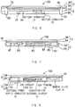
- Fig. 1 is a perspective view showing a portable computer which is a first embodiment of the information processing apparatus of the present invention, with a display unit that can be folded and opened against/from a main unit.
- Fig. 2 is a plan view in which the display unit of the computer shown in Fig. 1 is opened by approximately 180 degrees from the main unit.
- Figs.3 through 8 are a plan view as seen from the display unit side, a plan view, a front view, a rear view, a right side view and a left side view, as seen from the main unit side, in a condition where the display unit is folded against the main unit.
- This computer 100 is configured so that a main unit 2 and a display unit 3 can be opened and closed (folded) in directions indicated by an arrow R by hinges 1A (a first opening/closing mechanism) and 1B (a second opening/closing mechanism) surrounded by an A region and a B region which are described in detail later.
- a battery pack which is described in detail later is detachably accommodated in a battery accommodating section 2a provided between the hinges 1A and 1B of the main unit 2.
- surfaces of the main unit 2 and the display unit 3 which face each other will be referred to as a top surface and a front surface respectively, and surfaces opposite to them will be referred to as a bottom surface and a rear surface respectively.
- a keyboard 11, a pointing device 12 and the like are arranged on the top surface of the main unit 2 and covered with a non-metallic panel 2A, for example, plastic, as shown in Figs. 1 and 2 , whereas an air suction port 21 for a built-in cooling fan, a pair of legs 22, a sliding detachment levers 23 for removing the battery pack from the battery accommodating section 2a and the like are arranged on the bottom surface of the main unit 2 and covered with a metallic panel 2B made of magnesium alloy, aluminium alloy or the like as shown in Fig. 4 .
- a non-metallic panel 2A for example, plastic
- an air suction port 21 for a built-in cooling fan, a pair of legs 22, a sliding detachment levers 23 for removing the battery pack from the battery accommodating section 2a and the like are arranged on the bottom surface of the main unit 2 and covered with a metallic panel 2B made of magnesium alloy, aluminium alloy or the like as shown in Fig. 4 .
- a liquid crystal display (LCD) 31 and the like are arranged on the front surface of the display unit 3 as shown in Figs. 1 and 2 , and covered with a panel 3A made of a non-metallic material such as plastic, whereas the rear surface of the display unit 3, except an antenna cover 41 for covering an antenna described in detail later as shown in Fig. 3 , is covered entirely with a metallic panel 3B made of a magnesium alloy, an aluminium alloy or the like. Furthermore, a pair of protectors 42 which slightly protrudes from the rear surface to prevent the edges of the display unit 3 from being scratched by a desk is arranged on the rear surface of the display unit in the vicinities of the hinges 1A and 1B.
- a pair of protectors 42 which slightly protrudes from the rear surface to prevent the edges of the display unit 3 from being scratched by a desk is arranged on the rear surface of the display unit in the vicinities of the hinges 1A and 1B.
- arranged on the front surface of the main unit 2 is a pair of speakers 51, and arranged on the front surface of the display unit 3 are an antenna cover 61 for covering the antenna, a slide lever 62 for unlocking a pawl 32 which protrudes from the front surface of the display unit 3 from a hole 13 formed in the top surface of the main unit 2 and the like.
- battery pack connectors 71 and 72 for electrically mechanically connecting the battery pack are arranged at the battery accommodating section 2a on the rear surface of the main unit 2.
- a headphone terminal 81 arranged on a right side surface of the main unit 2 are a headphone terminal 81, a jog dial 82, a PC card slot 83 for a PC (Personal Computer) card of PCMCIA (Personal Computer Memory Card International Association) standard, an IEEE (Institute of Electrical and Electronics Engineers) 1394 terminal 84 for 4 pins, a modem terminal 85 for a modular jack and so on.
- PC Personal Computer
- PCMCIA Personal Computer Memory Card International Association
- the jog dial 82 is so arranged that its side partially protrudes from the right side surface of the main unit 2 and its top surface partially protrudes so as to become the same height as the keys on the keyboard 11.
- the jog dial 82 is a user interface, in which the dial is rotated and depressed, thereby offering excellent operability which permits easily carrying out a function for system setting and various functions of various application software.
- This jog dial 82 is configured so as to execute predetermined processing when a disk control knob 82a of a flat eye pattern is rotated in a direction indicated by an arrow a or b or depressed in a direction indicated by an arrow c as shown in Figs. 1 and 2 .
- a memory stick slot 91 for a memory stick used as a memory card arranged on a left side surface of the main unit 2 are a memory stick slot 91 for a memory stick used as a memory card, a USB (Universal Serial Bus) terminal 92, a connector 93 for external display, an air exhaust port 94, an external power supply connector 95 and so on.
- USB Universal Serial Bus
- a transparent plate 14 is fitted in part of the top surface of the main unit 2 corresponding to the memory stick slot 91 so that a label of a memory stick inserted into the memory stick slot 91 can be recognized from the top surface side of the main unit 2 thorough the transparent plate 14.
- Figs. 9(A) and 9(B) are side views seen from the left side and a detail plan view showing the hinge (the first opening/closing mechanism) 1A in a condition where the non-metallic panel 2A and the non-metallic panel 3B are removed from the main unit 2 and the display unit 3 respectively.
- the hinge 1A consists of a protruding portion 101 which is fixed with a screw at an edge of the metal panel 3B of the display unit 3 so as to protrude nearly perpendicularly to a display surface of the LCD 31 of the display unit 3 and a support portion 102 which is fixed with a screw at an edge of the main unit 2 so as to rotatably support a substantial tip portion of the protruding portion 101.
- the protruding portion 101 is made of material having high mechanical strength, for example, stainless steel (SUS) which is an iron-based material and formed in an L shape so that the display unit 3 maintains its strength in a stationary condition even while it is being opened and closed. An end of this protruding portion 101 is fixed with the screw at the edge of the display unit 3 and the other end of the protruding portion 101 is rotatably supported by the support portion 102.
- SUS stainless steel
- the support portion 102 consists of a strength maintaining portion 103 for maintaining mechanical strength and a coupling portion 104 for coupling with the protruding portion 101.
- the strength maintaining portion 103 is made of material having high mechanical strength, for example, stainless steel (SUS) which is iron-based material and is formed in an L shape so that the display unit 3 maintains its strength while being opened and closed.
- the coupling portion 104 has a shaft 104a which is supported by the strength maintaining portion 103, a stopper 104b fitted over the shaft 104a, a washer spring 104c and the like, and the other end of the protruding portion 101 is fitted over the shaft 104a and integrally coupled with the stopper 104b using the washer spring 104c and the like.
- Figs. 10(A) and 10(B) are a plan view and a side view as seen from the right side showing details of the hinge (second opening/closing mechanism) 1B in a condition where the non-metallic panel 2A and the non-metallic panel 3B are detached from the main unit 2 and the display unit 3 respectively.
- the hinge 1B consists of a protruding portion 111 which is fixed with a screw at the other end of the display unit 3 so as to protrude nearly perpendicularly to the display surface of the LCD 31 of the display unit 3 and a support portion 112 which is fixed with a screw at the other end of the main unit 2 so as to rotatably support a substantial tip portion of the protruding portion 111.
- the protruding portion 11 and the support portion 112 are configured substantially the same as the protruding portion 101 and the support portion 102 of the hinge 1A, except a central portion of a coupling portion 114 of the support portion 112 which is made hollow to pass wiring or the like.
- the protruding portions 101 and 111 can rotate with respect to the support portions 102 and 112 in directions indicated by R in Fig. 1 . Since it is sufficient to dispose only the protruding portions 101 and 111 on the display unit 3 side, a lower internal portion of the display unit 3, that is, space under the LCD 31 in particular can be utilized effectively.
- Figs. 11 through 14 are partial side sectional views showing a condition where the computer 100 in which the battery pack is mounted is put on a desk and the display unit 3 is opened from the main unit 2.
- the computer 100 When the computer 100 is set on a desk, for example, as shown in Fig. 11 , the computer 100 is set in a condition where a rear portion of the computer 100 is raised by the pair of legs 22 higher than a front portion, that is, the computer 100 is inclined frontward. In this condition, the computer 100 does not slip on the desk surface but is stable because rubber plates 22a, for example, are stuck on the bottom surfaces of the pair of legs 22.
- the pawl 32 protruding from the front surface of the display unit 3 is slided by sliding the slide lever 62, thereby releasing the pawl 32 from the hole 13 formed on the top surface of the main unit 2 and opening the display unit 3 from the main unit 2 as shown in Fig. 12 . Since a rear portion of the display unit 3 is separated from the support portions 102 and 112 by the length of the protruding portions 101 and 111, the display unit turns along a rear portion of the main unit 2.
- the rear portion of the main unit 2 is raised from the desk surface by the pair of legs 22, the rear portion of the display unit 3 is not brought into contact with the desk surface even when the display unit 3 is opened beyond 90 degrees with respect to the main unit 2, whereby the display unit 3 can be opened smoothly.
- the display unit 3 is opened to an angular position at which a user can see the LCD 31 of the display unit 3 clearly as shown in Fig. 13 .
- Fig. 15 is a perspective view showing a condition where a display unit of a computer as a conventional information processing apparatus is opened from a main unit and Fig. 16 is a side view of the computer under that condition.
- a display unit 520 is attached to a main unit 510 so as to be capable of opening and closing by the hinge 530 which is composed of a convex portion 531 formed nearly at the center of a main unit 510 and a concave portion 532 formed nearly at the center of the display unit 520 and engaged with the convex portion 531.
- Fig. 17 is a perspective view showing a condition where a display unit of another computer as a conventional information processing apparatus is opened from a main unit and Fig. 18 is a side view of the computer under that condition.
- a display unit 620 is attached to a main unit 610 so as to be capable of opening and closing by a pair of hinges 630.
- a battery pack 640 is detachably inserted between the pair of hinges 630.
- a user For use of the computer 500 or 600 put on a desk surface, a user must move his eyes between a keyboard 511 or 611 of the main unit 510 or 610 and a screen 521 or 621 of the display unit 520 or 620.
- the computers 500 and 600 have the main units 510, 610 and display units 520, 620 of an identical width a, the screens 521, 621 of an identical width b, the keyboards 511, 611 of an identical width c, and regions of an identical distance d under the screens 521, 621 of the display units 520, 620 which can accommodate substrates and the like.
- a distance between a center axis 630a of the hinges 630 and a lower end 621a of the screen 621 is denoted by d2.
- the minimum movement angles ⁇ 1 and ⁇ 2 of the user's eyes that is, angles formed by upper ends 511a, 611a of the keyboards 511, 611, visual points E and lower ends 521a, 621a of the screens 521, 621, and the maximum movement angles ⁇ 1 and ⁇ 2 of the user's eyes, that is, the angles formed by lower ends 511b, 611b of the keyboards 511, 611, the visual points E and the upper ends 521b, 621b of the screens 521, 621 are greatly influenced by relative positional relations of the center axes 530 and 630a of the hinges 530 and 630, respectively.
- the screens 521 and 621 are arranged at locations apart by the distance d of the regions in which the substrates and the like can be disposed, whereby the minimum movement angles 1 ⁇ and ⁇ 2 as well as the maximum movement angles ⁇ 1 and ⁇ 2 of the user's eyes are enlarged. Accordingly, which causes a problem that a user is easy to get tired under long term use, thereby lowering working efficiency.
- Fig. 19 is a side view of the computer 100 having the main unit 2 and the display unit 3 of a width a, the LCD 31 of a width b, the key board 11 of a width c, and the region of a distance d under the LCD 31 of the display unit 3 in which the substrate and the like can be accommodated, in correspondence with those of the conventional computers 500 and 600 shown in Figs. 29 and 31 .
- a distance d0 from the center axes 1a and 1b of the hinges 1A and 1B of the computer 100 to the lower end 31a of the LCD 31 in this embodiment is shorter than the distance d of the region under the LCD 31 of the display unit 3 in which the substrate and the like can be accommodated.
- the minimum movement angle ⁇ 0 of user's eyes that is, an angle formed by an upper end 11a of the keyboard 11, a visual point E and a lower end 31a of the LCD 31, and the maximum movement angle ⁇ 0 of the user's eyes, that is, an angle formed by a lower end 11b of the keyboard 11, the visual point E and an upper end 31b of the LCD 31 are smaller than the minimum movement angles ⁇ 1, ⁇ 2 and the maximum movement angles ⁇ 1, ⁇ 2 of the user's eyes in the conventional computers 500, 600.
- This computer 100 therefore shortens movement distances of eyes during operation and hardly tires a user even in a long-term use, thereby enhancing working efficiency.
- the display unit 3 and the main unit 2 can be substantially leveled as shown in Fig. 14 by further opening the display unit from the main unit 2.
- the protectors 42 which slightly protrude from the rear portion of the display unit 3 protect the rear portion of the display unit 3, thereby preventing the rear portion from being scratched due to rubbing with the desk surface.
- Fig. 20 is a perspective view of a computer of which the display unit is opened from the main unit, as a conventional information processing apparatus and Fig. 21 is a side view of the computer.
- a display unit 420 is attached to a main unit 410 by a pair of hinges 430 so as to open and fold.
- a battery pack 440 is detachably disposed between the pair of hinges 430.
- This computer 400 is put with space reserved between a desk surface and a bottom surface by a leg 411 disposed at the bottom surface of a front portion of the main unit 410 and a leg 441 disposed on the bottom surface of the battery pack 440, in order to take in cooling air for built-in electronic parts through an air suction port (not shown) formed at the bottom surface of the main unit 410.
- the computer 100 does not allow an opening to be formed, unlike the conventional computer, and has a good appearance since the battery accommodating section 2a from which the battery pack has been detached is concealed by a pent roof portion 2AA of the non-metallic panel 2A made of plastic or the like which covers the top surface of the main unit 2 as shown in Fig. 13 .
- the computer 400 While the conventional computer 400 is operated with an AC power supply after detaching the battery pack 440 from the computer 400, the computer 400 is supported by the leg 411 disposed at the bottom surface of the front portion of the main unit 410 and the bottom surface of a rear portion of the main unit 410. Accordingly, the computer 400 causes a problem that the air suction port which is formed at the bottom surface of the main unit 410 is half closed by the desk surface or the like, thereby incapable of sufficiently cooling the built-in electronic parts.
- the pair of legs 22 disposed on the main unit 2 reserves the gap between the air suction port 21 of the bottom surface of the main unit 2 and the desk surface, thereby not closing the air suction port, unlike the conventional computer, and being capable of sufficiently cooling electronic parts.
- the conventional computer 400 allows the main unit 410 to be inclined toward the display unit 420 side as shown in Fig. 23 , thereby causing a problem that the main unit 410 is easy to turn over toward the unfolded display unit 420 side and thus the display unit 420 cannot be opened and closed smoothly.
- the computer 100 of this embodiment is supported by the pair of legs 22 as shown in Fig. 13 and the main unit 2 is maintained stably on the desk surface even while the battery pack is detached, thereby allowing the display unit 3 to be opened and closed with no change between a battery pack detached condition and a battery pack attached condition.
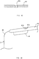
- Fig. 24 is a diagram showing an internal configuration of the display unit 3 with the non-metallic panel 3A removed from the front surface of the display unit 3.
- a light source circuit (inverter circuit) 33 for the LCD 31 is disposed under the LCD 31, a driving circuit 34 for the LCD 31 is disposed on a left side of the LCD 31, an antenna module 35 is disposed over the LCD31 and a transception module 36 is disposed on a right side of the LCD 31.
- an interior of a lower portion of the display unit 3, that is, the space under the LCD 31 in particular can be utilized effectively.
- a conventional light source circuit (inverter circuit) is disposed on the right side of an LCD
- the light source circuit (inverter circuit) 33 of this embodiment is disposed under the LCD
- the transception module 36 is disposed on the right side of the LCD 31
- the antenna module 35 is disposed over the LCD 31 in the vicinity of the transception module 36 which is preferable from a viewpoint of sensitivity so as to be capable of adopting Bluetooth.
- the Bluetooth (hereinafter referred to as BT) is a name of a short-distance radio communication technique for which a standardization activity was started by five companies in Japan, Europe and the United States in 1998, and a BT system adopts a maximum data transmission speed of 1 M bits/second (effectively 721 k bits/second) and a maximum transmission distance of 10 m.
- the BT system sets 79 channels having a bandwidth of 1 MHz in an ISM (industrial scientific) band of 2.4 GHz which can be utilized by a user with no license and transmits radio waves by a frequency hopping type of spread spectrum technique which switches channels 1600 time per second.
- ISM industrial scientific
- An Appliance which adopts the BT is divided into a master which determines a frequency hopping pattern and slaves which are communication mates of the master.
- the master is capable of communicating with seven slaves at the same time.
- a subnet which is composed of eight appliances at maximum of a master and slaves is referred to as a piconet.
- a slave of a piconet can function as a slave of two or more piconets at the same time.
- Figs. 25(A), 25(B) and 25(C) are a view of surroundings of the antenna module 35 as seen from the rear surface of the display unit 3, a view of the surrounding of the antenna module 35 as seen from the front surface of the display unit 3 and a sectional view taken along an A-A line.
- the antenna module 35 has such a configuration that a BT antenna 35a for BT communication and a connector 35b for the transception module 36 are mounted on a substrate 35c.
- the antenna module 35 is built in the display unit 3 from viewpoints of portability and esthetic appearance, but as the rear part of the display unit 3 is covered with the metallic panel 3B, transception of radio waves is hindered if the BT antenna 35a completely is covered with the metallic panel 3B.
- the antenna module 35 is therefore disposed so that the BT antenna 35a is over the display unit 3 and slightly protrudes from an upper end UP of the metallic panel 3B, and the antenna module 35 including the protruding portion of the antenna 35a is covered with an antenna cover 61 which is made of non-metallic material such as plastic.
- the antenna module 35 may be disposed so that the whole BT antenna 35a protrude from the upper end of the metallic panel 3B.
- the BT antenna which protrudes upward improves radio wave transception quality in a left-right direction of the display unit.
- a notch 37 is formed in the metallic panel 3B at a location where the antenna module 35 is disposed. This notch 37 is disposed so that a distance d1 from a left side of the notch 37 in Fig. 25(A) to a high sensitivity side of the BT antenna 35a, that is, to a side opposite to a power supply port 35aa is longer than a distance d2 from a right side of the notch 37 in Fig. 25(A) to the power supply port 35aa for the BT antenna 35a.
- the notch 37 is covered with an antenna cover 41 which is made of non-metallic material such as plastic.
- the BT antenna 35a which is disposed on the substrate 35c of the antenna module 35 is directed outside the display unit 3 as shown in Fig. 25(C) in this embodiment, the BT antenna may be disposed as to be directed inside the display unit 3.
- the transception module 36 has such a configuration that an RF processor 36a which is to be connected to the connector 35b electrically conductive to the power supply port 35aa for the antenna module 35 and a baseband processor 36b which is to be connected to a micro computer in the main unit 2 are mounted on a substrate 36c, as shown in Fig. 24 .
- Transmission data to be transferred by the BT communication is generated by microcomputer's processing and passed to the baseband processor 36b.
- the baseband processor 36b converts the data passed from the microcomputer into packets for the BT communication. At this time, the baseband processor 36b adds an error correction detecting code and various kinds of data for communication.
- the data generated by the baseband processor 36b is passed to the RF processor 36a, the data is converted into analog data for transmission.
- the RF processor 36a modulates the passed digital data, superimposes the data on radio waves of 2.4 GHz band and sends out the data from the BT antenna 35a.
- carrier waves different frequencies are selected for individual slots (sets of data) by frequency hopping.
- a signal received by the BT antenna 35a is demodulated by the RF processor 36a into digital data and subjected to an error check and the like by the baseband processor 36b. Then, the digital data is passed to the microcomputer for executing corresponding processing.
- Figs. 26(A), 26(B) and 26(C) are a plan view, a side view and a right side view showing an example of a battery pack, respectively.
- This battery pack 200 has such a structure that a lithium ion secondary battery or the like, for example, is contained in a case 201.
- the case 201 is also two or more times as large as conventional one and is made, for example, of plastic, and a plurality of battery cells, twice or more times as many as a conventional one, is arranged in the case 201, for example, in two rows, in contrast to conventional battery cells arranged in a row.
- the battery pack 200 is guided and inserted between the hinges 1A and 1B, and connected electrically and mechanically to the main unit 2.
- a guide mechanism and connection mechanism are formed for the battery pack 200 and the main unit 2, whereby the battery pack 200 and the main unit 2 are attachable and detachable to and from each other.
- a pair of attaching portions 202, an electric connection terminal 203 and a pair of grooves 204 are formed on the outer surface of the case 201 as shown in Figs. 26 and 27 .
- Each attaching portion 202 is formed so as to protrude from a surface of the case 201 which is to be brought into contact with the main unit 2.
- the electric connection terminal 203 is disposed on the surface to be brought into contact with the main unit 2 so as to protrude between the attaching portions 202.
- the grooves 204 are respectively formed at the left and right edges of the case 201 along a horizontal direction N.
- battery connectors 71 and 72 which have concave shapes corresponding to the attaching portions 202 and the electric connection terminal 203 are formed as shown in Fig. 27 . Furthermore, a pair of protruding portions 73 which can be fitted into the grooves 204 is formed at the both sides of the rear end of the battery accommodating portion 2a of the main unit 2, which are located substantially over the legs 22.
- the pair of protruding portions 73 of the main unit 2 are fitted into the pair of grooves 204 of the battery pack 200 by moving the surface of the battery pack 200 which is to be brought into contact with the main unit 2 toward the battery accommodating section 2a as shown in Figs. 28 and 30 . Accordingly, the battery pack 200 is capable of moving in the battery accommodating section 2a horizontally along the protruding portions 73.
- the pair of attaching portions 202 and the electric connection terminal 203 of the battery pack 200 are fitted into the connectors 71 and 72 of the main unit 2 as shown in Figs. 29 and 31 . Accordingly, the battery pack 200 is removably attached to the main unit 2 securely, electrically, and mechanically.
- the grooves 204 and the protruding portions 73 can guide the battery pack 200 as described above, it is possible to prevent the electric connection terminal 203 from being broken due to stresses produced at steps of attaching and detaching the electric connection terminal 203 of the battery pack 200 to and from the battery connector 72.
- driving power is supplied from the battery pack 200 to the main unit 2 via the electric connection terminal 203 and the battery connector 72.
- the above described guide mechanism is a combination of the grooves 204 which are formed at the both ends of the battery pack 200 and the protruding portions 73 which are formed on the surfaces of the main unit 2 facing the both ends of the battery pack 200, it is needless to say that the grooves 204 and the protruding portions 73 may be formed in an opposite way. That is, it is possible to form grooves similar to the grooves 204 on the surfaces of the main body 2 corresponding to the both ends of the battery pack 200 and to form protruding portions similar to the protruding portions 73 at the both ends of the battery pack 200.
- Fig. 32 is a perspective view showing a portable computer 700 as a second embodiment of the information processing apparatus in the present invention.
- the computer 700 of this embodiment has an LED light conduction lens unit 800 disposed as a light emitting means at an antenna cover 61 or the like.
- This light conduction unit 800 is equipped with an LED 900 which is a light emitting diode.
- the portable computer 700 of this embodiment has a light emitting transparent portion 61a which is partially composed of a transparent member and formed in an antenna cover 61 that is a side cover.
- the LED light conduction lens unit 800 is disposed in the antenna cover 61 at a position corresponding to the light emitting transparent portion 61a, light from the LED light conduction unit 800 is emitted outside the portable computer 700 through the light emitting transparent portion 61a.
- the LED light conduction lens unit 800 is configured to emit light from the LED 900 while communication is carried out in the above described BT mode. Specifically, the LED 900 in the LED light conduction lens unit 800 lights or flickers while a BT antenna 35a which is disposed in the vicinity of the LED light conduction lens unit 800 in the antenna cover 61 receives and transmits a signal.
- a user of the portable computer 700 can recognize that the BT antenna 35a is transmitting or receiving a signal, while the LED 900 of the LED light conduction lens unit 800 is lighting or flickering, and when he sets the LED light conduction lens unit 800 in a favorable direction for communication, the BT antenna in the vicinity of the lens unit 800 is also set in the favorable direction for communication accordingly. It is therefore easy for the user to comprehend a directivity of radio communication.
- the user can easily comprehend a reception or transmission sensitivity in a poor communication condition because the LED 900 of the LED light conduction lens unit 800 does not light or flicker.
- Fig. 33 is a diagram showing an arrangement of the light emitting transparent portion 61a disposed in the antenna cover 61 shown in Fig. 32 as seen from outside the display unit 3.
- the light emitting transparent portion 61a is disposed in the antenna cover 61 so as to be easily recognized from both the inside which is the front surface side of the display unit 3 and the outside, as shown in Fig. 33 .
- the BT antenna 35a receives a radio signal of the BT mode and a user is easy to recognize lighting or flickering of the LED 900 when the LED 900 of the LED light conduction lens unit 800 lights or flickers.
- Fig. 34 is a diagram showing an arrangement of the display unit 3, the metallic panel 3B, the antenna cover 61 that is a side cover, the antenna cover 41 that is also a side cover, the light emitting transparent potion 61a and the like which are shown in Fig. 33 .
- Fig. 35 is a schematic sectional view showing an arrangement of the LED light conduction lens unit 800, the antenna cover 61 and the light emitting transparent portion 61a.
- a dome-shaped lens 810 of the LED light conduction lens unit 800 which emits light from the LED is arranged right under the light emitting transparent portion 61a as shown in Fig. 35 . Therefore, the LED light through the dome-shaped lens 810 is emitted outside through the light emitting transparent portion 61a wastelessly.
- Fig. 36 is a diagram of the notch 37 formed in the metallic panel 3B of the display unit 3 as seen from the LCD 31 side which is the display side of the display unit 3.
- a sensitivity of the BT antenna 35a is enhanced by forming the notch 37 in the metallic panel 3B of the display unit 3 and disposing the BT antenna 35a in this notch 37 as described above.
- the antenna cover 41 which is made of plastic or the like shown in Fig. 37 is disposed in this notch 37.
- Fig. 38 is a diagram of the antenna cover 41 as seen from a direction indicated by an arrow.
- An antenna cover notch 41a is formed in the antenna cover 41 as shown in Figs. 37 and 38 , and the antenna cover 41 is disposed so that the dome-shaped lens 810, and BT antenna 35a and the like protrude from the antenna cover notch 41a as described later.
- Fig. 39 is a diagram showing a condition where the antenna cover 41 shown in Fig. 37 is disposed in the notch 37 shown in Fig. 36 , the LED 900 is not mounted on the antenna cover 41 and the LED light conduction lens unit 800 is disposed. In this condition, the LED light conduction lens unit 800 is disposed so that the dome-shaped lens 810 protrudes from the antenna cover notch 41a protrudes upward from the antenna cover notch 41a in the drawing.
- Figs. 40(a), 40(b) and 40(c) are diagrams showing the LED light conduction lens unit 800 shown in Fig. 39 .
- the LED light conduction lens unit 800 has a holder portion 830 in which the LED is to be disposed and the dome-shaped lens 810 as shown in Fig. 40(a) . Further, disposed right under the dome-shaped lens 810 in the drawing is a scattering portion 820 for scattering light from the LED, thereby emitting the light uniformly from the dome-shaped lens 810.
- the scattering portion 820 is configured to have continuous peaks so that the light emitted from the LED are scattered by inclined surfaces of the peaks and the like, and not concentrated on one point.
- the LED 900 which is disposed on a substrate 35c described later is arranged under the scattering portion 820 as shown in Figs. 40(a) and 40(b) .
- Fig. 41 is a diagram showing an arrangement where the LED 900, the BT antenna 35a and the like are disposed on the substrate 35c that is the antenna substrate.
- an LED power supply 35d which supplies electricity to the LED 900 as shown in Fig. 41 . Thereby, electricity is supplied to the LED 900 by way of this substrate 35c.
- a power supply port connector 35e for supplying electricity to the power supply port 35aa.
- electricity is supplied also to the power supply port 35aa for the BT antenna 35a by way of this substrate 35c.
- Fig. 42 is a diagram showing an arrangement where the substrate 35c having the LED light conduction lens unit 800 and the like mounted thereon is disposed on the antenna cover 41 shown in Fig. 37 and the antenna cover 41 is disposed in the notch 37 shown in Fig. 36 .
- Fig. 42 is a diagram of this arrangement as seen from the outside of the metallic panel 3B of the display unit 3. As shown in Fig. 42 , a portion of the LED light conduction lens unit 800, a portion of the substrate 35c and the BT antenna 35a disposed on the substrate 35c protrude upward from the antenna cover notch 41a of the antenna cover 41 as shown in Fig. 42 .
- the BT antenna 35a is formed so as to protrude in particular, a radio signal can be transmitted and received with a high sensitivity without being hindered by the metallic panel 3B of the display unit 3.
- Fig. 43 is a schematic plan view showing an arrangement of the antenna cover 41, the BT antenna 35a, the LED light conduction lens unit 800, the substrate 35c and the like shown in Fig. 42 . That is, Fig. 43 is a diagram of a condition where the antenna cover 61 to be attached to a top end of the display unit 3 is not attached, as seen from the top end side of the display unit 3.
- Fig. 44 is a diagram showing an arrangement where the antenna cover 61 is disposed at the top end of the display unit 3 shown in Fig. 42 . That is, Fig. 44 is a diagram of a condition where the non-metallic panel 3A is removed from the front surface of the display unit 3 and the antenna cover 61 is disposed, as seen from the LCD 31 side which is opposite to the side in Fig. 42 . When this condition is seen from the outside of the display unit 3, it will be Fig. 34 .
- the portable computer 700 of this embodiment is capable of receiving and transmitting a radio signal with a high sensitivity in the BT mode as described above. Since the light emitting transparent portion 61a of the antenna cover 61 lights or flickers during transception of the radio signal, a communication sensitivity can be recognized clearly. Since the BT antenna 35a is disposed in the vicinity of the light emitting transparent portion 61a, a user can easily recognize a location of the BT antenna and comprehend a directivity of radio waves. Furthermore, a communicating mate understands that reception is facilitated by transmission toward the lighting or flickering position and can carry out communication smoothly.
- Figs. 45 and 46 are diagrams showing a modification example of the computer 700 of the above described second embodiment.
- this modification example uses, in place of the light emitting transparent portion 61a, a light emitting notch 61b formed in the antenna cover 61. Thereby, the dome-shaped lens 810 of the LED light conduction lens unit 800 exposed from the light emitting notch 61b as shown in Fig. 46 .
- the notch is formed in part of the metallic panel in each of the above described embodiments, it is possible to use, in place of the metallic panel, a panel made of a non-metallic member which has an inside surface treated for shielding from electromagnetic waves.
- Methods for shielding treatment against the electromagnetic waves are a method for coating with an electrically conductive paint, a method for metal plating, a method for depositing a metal, a method for spreading a metal foil and the like.
- the portable computers are mentioned as examples in the above described embodiments, the present invention is not limited to this and the present invention is similarly applicable also to other kinds of information processing apparatuses, for example, portable information terminals, portable telephones and radio devices.
- the present invention is configured to dispose an antenna in a notch formed in a metallic panel, thereby making it possible to allow radio waves to be securely received by the antenna or transmitted from the antenna without being intercepted by the metallic panel, so that accurate data can always be received and transmitted securely and rapidly.
- the present invention can be applied to portable personal computers, mobile computers, and other kinds of information processing apparatuses, for example, portable information apparatuses such as a portable information terminal, a portable telephone and a radio device.
- portable information apparatuses such as a portable information terminal, a portable telephone and a radio device.
Landscapes
- Engineering & Computer Science (AREA)
- Computer Hardware Design (AREA)
- Theoretical Computer Science (AREA)
- General Engineering & Computer Science (AREA)
- Physics & Mathematics (AREA)
- General Physics & Mathematics (AREA)
- Human Computer Interaction (AREA)
- Power Engineering (AREA)
- Mathematical Physics (AREA)
- Power Sources (AREA)
- Structure Of Receivers (AREA)
- Support Of Aerials (AREA)
- Transmitters (AREA)
- Casings For Electric Apparatus (AREA)
- Details Of Aerials (AREA)
Description
- The present invention relates to an information processing apparatus which has a display unit foldable against a main body.
- There have recently been offered as commercial products a large number of portable information processing apparatuses such as notebook personal computers and mobile computers. Such an information processing apparatus consists of a main unit and a display unit, and the display unit can be closed and opened against/from the main unit with a hingeable means. Such an information processing apparatus is recently equipped with an antenna and the like so that data can be exchanged between information processing apparatuses.
-
Fig. 47 is a perspective view showing a conventional information processing apparatus in which a display unit is opened from a main unit of this computer which is equipped with an antenna. - This
computer 400 consists of amain unit 410 having a metallic panel and adisplay unit 420 having a metallic panel which can be folded and opened against/from themain unit 410. Anantenna 430 is rotatably disposed on a side surface of themain unit 410. Such theantenna 430 is rotated so as to be erected from themain unit 410 as shown in the drawing when theantenna 430 is to be used, while theantenna 430 is rotated to be nearly in parallel with themain unit 410 when theantenna 430 is not to be used. - In the above described
conventional computer 400 in which the metallic panel produces an adverse influence on the antenna, theantenna 430 is disposed so as to protrude from a side surface of themain unit 410. Accordingly, theantenna 430 causes a problem that articles are liable to be caught by theantenna 430, whereby theantenna 430 or others may be broken. Furthermore, theantenna 430 has a defect that it may not match themain unit 410 and the like in design. -
Fig. 48 is a perspective view showing another conventional information processing apparatus in which a display unit is open from a main unit of this computer having an antenna and the like. - This
computer 500 has adisplay unit 520 which is attached to amain unit 510 so as to be capable of freely opening and closing. Anantenna 530 is built inside a side surface of themain unit 510. - Such a
computer 500 is capable of solving the above described problems, but since radio waves coming from the left and the front as seen from a user pass through inside themain unit 510 and then attain to theantenna 530, thecomputer 500 causes a problem that radio waves are troubled by built-in electronic parts in their courses, thereby lowering a sensitivity of theantenna 530. - The present invention therefore has an object to solve the above described problems and provide an information processing apparatus which is equipped with an antenna having a high sensitivity.
- The present invention accomplishes the above described object by equipping an information processing apparatus with a display unit having a display panel of which the rear side is covered with a metallic panel, an antenna member which is disposed in a notch formed in part of the above described metallic panel and a cover of a non-metallic member which is disposed in the above described notch so as to cover the above described antenna member as defined in
claim 1. - The above described configuration in which the antenna is disposed in the notch formed in the metallic panel allows radio waves to be securely received by the antenna or transmitted from the antenna without being intercepted by the metallic panel. Accordingly, the configuration makes it possible to always receive and transmit accurate data and the like securely and rapidly.
- Alternatively, the apparatus as defined in
claim 12 is provided. -
-
Fig. 1 is a perspective view showing a portable computer having a display unit which can be folded and opened against/from a main unit as a first embodiment of the information processing apparatus of the present invention. -
Fig. 2 is a plan view of the computer shown inFig. 1 in a condition where the display unit is opened by 180 degrees from the main unit. -
Fig. 3 is a plan view of the computer shown inFig. 1 as seen from the display unit side in a condition where the display unit is folded against the main unit. -
Fig. 4 is a plan view of the computer shown inFig. 3 as seen from the main unit side. -
Fig. 5 is a front side view of the computer shown inFig. 3 . -
Fig. 6 is a rear side view of the computer shown inFig. 3 . -
Fig. 7 is a right side view of the computer shown inFig. 3 . -
Fig. 8 is a left side view of the computer shown inFig. 3 . -
Fig. 9 is a detail side view and plan view illustrating a hinge (first opening/closing mechanism) shown inFig. 1 . -
Fig. 10 is a detail side view and a plan view illustrating a hinge (second opening/closing mechanism) shown inFig. 1 . -
Fig. 11 is a first partial side view showing a condition where the computer shown inFig. 1 having a battery pack inserted therein is put on a desk and the display unit is closed from the main unit. -
Fig. 12 is a second partial side view showing a condition where the computer shown inFig, 1 having the battery pack inserted therein is put on the desk and the display unit is opened against the main unit. -
Fig. 13 is a third partial side view showing a condition where the computer shown inFig. 1 having the battery pack inserted therein is put on the desk and the display unit is opened from the main unit. -
Fig. 14 is a fourth partial side view showing a condition where the computer shown inFig. 1 having the battery pack inserted therein is put on the desk surface and the display unit is opened from the main unit. -
Fig. 15 is a perspective view showing a condition where a display unit of a computer as a conventional information processing apparatus is opened from a main unit. -
Fig. 16 is a side view of the computer shown inFig. 15 . -
Fig. 17 is a perspective view showing a condition where a display unit of another computer as a conventional information processing apparatus is opened from a main unit. -
Fig. 18 is a side view of the computer shown inFig. 17 . -
Fig. 19 is a side view showing a condition where the display unit of the computer shown inFig. 1 is opened from the main unit. -
Fig. 20 is a perspective view showing a condition where a display unit of a computer as a conventional information processing apparatus is opened from a main unit. -
Fig. 21 is a side view of the computer shown inFig. 20 . -
Fig. 22 is a perspective view showing a problematic point of the computer shown inFig. 20 . -
Fig. 23 is a side view showing a problematic point of the computer shown inFig. 20 . -
Fig. 24 is a diagram showing an internal configuration of the display unit in a condition where a non-metallic panel covering the front surface of the display unit is removed from the display unit shown inFig. 1 . -
Fig. 25 is a diagram of surroundings of an antenna module shown inFig. 1 as seen from outside the display unit, a diagram of the surroundings as seen from inside the display unit and a sectional view taken along an A-A line. -
Fig. 26 is a plan view, a side view and a right side view showing an example of a battery pack for the computer shown inFig. 1 . -
Fig 27 is a perspective view showing an example of a battery pack for the computer shown inFig. 1 . -
Fig. 28 is a plan view showing a condition before inserting the battery pack in the computer shown inFig. 1 . -
Fig. 29 is a plan view showing a condition after the battery pack is inserted in the computer shown inFig. 1 . -
Fig. 30 is a side view showing the condition before the battery pack is inserted in the computer shown inFig. 1 . -
Fig. 31 is a side view showing the condition after the battery pack is inserted in the computer shown inFig. 1 . -
Fig. 32 is a perspective view showing a portable computer as a second embodiment of the information processing apparatus in the present invention. -
Fig. 33 is a plan view showing a condition where a display unit of the computer shown inFig. 32 is folded against a main unit as seen from the display unit side. -
Fig. 34 is a diagram showing arrangements of the display unit, an antenna cover, a light emitting transparent portion and the like shown inFig. 33 . -
Fig. 35 is a schematic sectional view showing arrangements of an LED light conduction lens unit, the antenna cover and the light emitting transparent portion. -
Fig. 36 is a schematic diagram of a notch formed in the display unit as seen from an LCD side which is a front surface side of the display unit. -
Fig. 37 is a schematic perspective view showing the antenna cover. -
Fig. 38 is a schematic diagram of the antenna cover shown inFig. 37 as seen from a direction indicated by an arrow inFig. 37 . -
Fig. 39 is a schematic diagram showing a condition where the antenna cover shown inFig. 37 is disposed in the notch shown inFig. 36 and the LED light conduction lens unit is disposed on the antenna cover. -
Fig. 40(a) is a schematic diagram showing the LED light conduction lens unit,Fig. 40(b) is a schematic plan view of the LED light conduction lens unit shown inFig. 40(a) and Fig. 40(c) is a schematic right side view of the LED light conduction lens unit shown inFig. 40(a) . -
Fig. 41 is a schematic diagram showing a condition where an LED, a BT antenna and the like are disposed on a substrate. -
Fig. 42 is a schematic diagram showing a condition where the substrate shown inFig. 41 is disposed on the antenna cover shown inFig. 37 and the antenna cover is disposed in the notch shown inFig. 36 . -
Fig. 43 is a schematic plan view showing arrangements of the LED light conduction lens unit, the BT antenna, the antenna cover and the like on the substrate shown inFig. 42 . -
Fig. 44 is a schematic diagram showing a condition of the antenna cover disposed over the top portion shown inFig, 42 as seen from the LCD side which is opposite toFig. 42 . -
Fig. 45 is a schematic sectional view showing a modification example of the portable computer in the second embodiment. -
Fig. 46 is a schematic perspective view showing a modification example of the portable computer according to the second embodiment. -
Fig. 47 is a perspective view showing a condition where a display unit of a computer having an antenna and the like as a conventional information processing apparatus is opened from a main unit. -
Fig. 48 is a perspective view showing a condition where a display unit of a computer having an antenna and the like as another conventional information processing apparatus is opened from a main unit. - Now, preferable embodiments of the present invention will be described in detail with reference to the accompanying drawings.
- The embodiments which are described below are specific preferable examples of the present invention in which various technically preferable definitions are made, and a scope of the present invention is not limited by these embodiment so far as a statement limitative of the present invention is not made in the following description.
-
Fig. 1 is a perspective view showing a portable computer which is a first embodiment of the information processing apparatus of the present invention, with a display unit that can be folded and opened against/from a main unit.Fig. 2 is a plan view in which the display unit of the computer shown inFig. 1 is opened by approximately 180 degrees from the main unit.Figs.3 through 8 are a plan view as seen from the display unit side, a plan view, a front view, a rear view, a right side view and a left side view, as seen from the main unit side, in a condition where the display unit is folded against the main unit. - This
computer 100 is configured so that amain unit 2 and adisplay unit 3 can be opened and closed (folded) in directions indicated by an arrow R byhinges 1A (a first opening/closing mechanism) and 1B (a second opening/closing mechanism) surrounded by an A region and a B region which are described in detail later. A battery pack which is described in detail later is detachably accommodated in abattery accommodating section 2a provided between thehinges main unit 2. In description that follows, surfaces of themain unit 2 and thedisplay unit 3 which face each other will be referred to as a top surface and a front surface respectively, and surfaces opposite to them will be referred to as a bottom surface and a rear surface respectively. - A
keyboard 11, apointing device 12 and the like are arranged on the top surface of themain unit 2 and covered with anon-metallic panel 2A, for example, plastic, as shown inFigs. 1 and2 , whereas anair suction port 21 for a built-in cooling fan, a pair oflegs 22, a sliding detachment levers 23 for removing the battery pack from thebattery accommodating section 2a and the like are arranged on the bottom surface of themain unit 2 and covered with ametallic panel 2B made of magnesium alloy, aluminium alloy or the like as shown inFig. 4 . - Furthermore, a liquid crystal display (LCD) 31 and the like, for example, are arranged on the front surface of the
display unit 3 as shown inFigs. 1 and2 , and covered with apanel 3A made of a non-metallic material such as plastic, whereas the rear surface of thedisplay unit 3, except anantenna cover 41 for covering an antenna described in detail later as shown inFig. 3 , is covered entirely with ametallic panel 3B made of a magnesium alloy, an aluminium alloy or the like. Furthermore, a pair ofprotectors 42 which slightly protrudes from the rear surface to prevent the edges of thedisplay unit 3 from being scratched by a desk is arranged on the rear surface of the display unit in the vicinities of thehinges - As shown in
Figs. 1 and5 , arranged on the front surface of themain unit 2 is a pair ofspeakers 51, and arranged on the front surface of thedisplay unit 3 are anantenna cover 61 for covering the antenna, aslide lever 62 for unlocking apawl 32 which protrudes from the front surface of thedisplay unit 3 from ahole 13 formed in the top surface of themain unit 2 and the like. - As shown in
Fig. 6 ,battery pack connectors battery accommodating section 2a on the rear surface of themain unit 2. - As shown in
Figs. 1 and7 , arranged on a right side surface of themain unit 2 are aheadphone terminal 81, ajog dial 82, aPC card slot 83 for a PC (Personal Computer) card of PCMCIA (Personal Computer Memory Card International Association) standard, an IEEE (Institute of Electrical and Electronics Engineers) 1394terminal 84 for 4 pins, amodem terminal 85 for a modular jack and so on. - The
jog dial 82 is so arranged that its side partially protrudes from the right side surface of themain unit 2 and its top surface partially protrudes so as to become the same height as the keys on thekeyboard 11. - The
jog dial 82 is a user interface, in which the dial is rotated and depressed, thereby offering excellent operability which permits easily carrying out a function for system setting and various functions of various application software. Thisjog dial 82 is configured so as to execute predetermined processing when adisk control knob 82a of a flat eye pattern is rotated in a direction indicated by an arrow a or b or depressed in a direction indicated by an arrow c as shown inFigs. 1 and2 . - As shown in
Figs. 1 and8 , arranged on a left side surface of themain unit 2 are amemory stick slot 91 for a memory stick used as a memory card, a USB (Universal Serial Bus) terminal 92, aconnector 93 for external display, anair exhaust port 94, an externalpower supply connector 95 and so on. - A
transparent plate 14 is fitted in part of the top surface of themain unit 2 corresponding to thememory stick slot 91 so that a label of a memory stick inserted into thememory stick slot 91 can be recognized from the top surface side of themain unit 2 thorough thetransparent plate 14. -
Figs. 9(A) and 9(B) are side views seen from the left side and a detail plan view showing the hinge (the first opening/closing mechanism) 1A in a condition where thenon-metallic panel 2A and thenon-metallic panel 3B are removed from themain unit 2 and thedisplay unit 3 respectively. - The
hinge 1A consists of a protrudingportion 101 which is fixed with a screw at an edge of themetal panel 3B of thedisplay unit 3 so as to protrude nearly perpendicularly to a display surface of theLCD 31 of thedisplay unit 3 and asupport portion 102 which is fixed with a screw at an edge of themain unit 2 so as to rotatably support a substantial tip portion of the protrudingportion 101. - The protruding
portion 101 is made of material having high mechanical strength, for example, stainless steel (SUS) which is an iron-based material and formed in an L shape so that thedisplay unit 3 maintains its strength in a stationary condition even while it is being opened and closed. An end of this protrudingportion 101 is fixed with the screw at the edge of thedisplay unit 3 and the other end of the protrudingportion 101 is rotatably supported by thesupport portion 102. - The
support portion 102 consists of a strength maintaining portion 103 for maintaining mechanical strength and acoupling portion 104 for coupling with the protrudingportion 101. The strength maintaining portion 103 is made of material having high mechanical strength, for example, stainless steel (SUS) which is iron-based material and is formed in an L shape so that thedisplay unit 3 maintains its strength while being opened and closed. Thecoupling portion 104 has ashaft 104a which is supported by the strength maintaining portion 103, astopper 104b fitted over theshaft 104a, awasher spring 104c and the like, and the other end of the protrudingportion 101 is fitted over theshaft 104a and integrally coupled with thestopper 104b using thewasher spring 104c and the like. -
Figs. 10(A) and 10(B) are a plan view and a side view as seen from the right side showing details of the hinge (second opening/closing mechanism) 1B in a condition where thenon-metallic panel 2A and thenon-metallic panel 3B are detached from themain unit 2 and thedisplay unit 3 respectively. - The
hinge 1B consists of a protrudingportion 111 which is fixed with a screw at the other end of thedisplay unit 3 so as to protrude nearly perpendicularly to the display surface of theLCD 31 of thedisplay unit 3 and asupport portion 112 which is fixed with a screw at the other end of themain unit 2 so as to rotatably support a substantial tip portion of the protrudingportion 111. - The protruding
portion 11 and thesupport portion 112 are configured substantially the same as the protrudingportion 101 and thesupport portion 102 of thehinge 1A, except a central portion of acoupling portion 114 of thesupport portion 112 which is made hollow to pass wiring or the like. - By the
hinges portions support portions Fig. 1 . Since it is sufficient to dispose only the protrudingportions display unit 3 side, a lower internal portion of thedisplay unit 3, that is, space under theLCD 31 in particular can be utilized effectively. -
Figs. 11 through 14 are partial side sectional views showing a condition where thecomputer 100 in which the battery pack is mounted is put on a desk and thedisplay unit 3 is opened from themain unit 2. - When the
computer 100 is set on a desk, for example, as shown inFig. 11 , thecomputer 100 is set in a condition where a rear portion of thecomputer 100 is raised by the pair oflegs 22 higher than a front portion, that is, thecomputer 100 is inclined frontward. In this condition, thecomputer 100 does not slip on the desk surface but is stable becauserubber plates 22a, for example, are stuck on the bottom surfaces of the pair oflegs 22. - In this condition, the
pawl 32 protruding from the front surface of thedisplay unit 3 is slided by sliding theslide lever 62, thereby releasing thepawl 32 from thehole 13 formed on the top surface of themain unit 2 and opening thedisplay unit 3 from themain unit 2 as shown inFig. 12 . Since a rear portion of thedisplay unit 3 is separated from thesupport portions portions main unit 2. Furthermore, since the rear portion of themain unit 2 is raised from the desk surface by the pair oflegs 22, the rear portion of thedisplay unit 3 is not brought into contact with the desk surface even when thedisplay unit 3 is opened beyond 90 degrees with respect to themain unit 2, whereby thedisplay unit 3 can be opened smoothly. - The
display unit 3 is opened to an angular position at which a user can see theLCD 31 of thedisplay unit 3 clearly as shown inFig. 13 . -
Fig. 15 is a perspective view showing a condition where a display unit of a computer as a conventional information processing apparatus is opened from a main unit andFig. 16 is a side view of the computer under that condition. - In this
computer 500, adisplay unit 520 is attached to amain unit 510 so as to be capable of opening and closing by thehinge 530 which is composed of aconvex portion 531 formed nearly at the center of amain unit 510 and aconcave portion 532 formed nearly at the center of thedisplay unit 520 and engaged with theconvex portion 531. -
Fig. 17 is a perspective view showing a condition where a display unit of another computer as a conventional information processing apparatus is opened from a main unit andFig. 18 is a side view of the computer under that condition. - In this
computer 600, adisplay unit 620 is attached to amain unit 610 so as to be capable of opening and closing by a pair ofhinges 630. Abattery pack 640 is detachably inserted between the pair ofhinges 630. - For use of the
computer keyboard main unit screen display unit computers main units display units screens keyboards screens display units center axis 630a of thehinges 630 and alower end 621a of thescreen 621 is denoted by d2. - In this case, it will be understood that the minimum movement angles α1 and α2 of the user's eyes, that is, angles formed by
upper ends keyboards lower ends screens lower ends keyboards screens hinges - In other words, since the above described
computers hinges main units screens screens - On the other hand,
Fig. 19 is a side view of thecomputer 100 having themain unit 2 and thedisplay unit 3 of a width a, theLCD 31 of a width b, thekey board 11 of a width c, and the region of a distance d under theLCD 31 of thedisplay unit 3 in which the substrate and the like can be accommodated, in correspondence with those of theconventional computers Figs. 29 and31 . Since thedisplay unit 3 is disposed so as to be perpendicular to the protrudingportions hinges main unit 2, the rear portion of thedisplay unit 3 turns behind the rear portion of themain unit 2 and theLCD 31 comes close to thekeyboard 11. In other words, a distance d0 from the center axes 1a and 1b of thehinges computer 100 to thelower end 31a of theLCD 31 in this embodiment is shorter than the distance d of the region under theLCD 31 of thedisplay unit 3 in which the substrate and the like can be accommodated. - Accordingly, using the computer according to this embodiment, the minimum movement angle α0 of user's eyes, that is, an angle formed by an
upper end 11a of thekeyboard 11, a visual point E and alower end 31a of theLCD 31, and the maximum movement angle β0 of the user's eyes, that is, an angle formed by alower end 11b of thekeyboard 11, the visual point E and anupper end 31b of theLCD 31 are smaller than the minimum movement angles α1, α2 and the maximum movement angles α1, β2 of the user's eyes in theconventional computers computer 100 therefore shortens movement distances of eyes during operation and hardly tires a user even in a long-term use, thereby enhancing working efficiency. - Furthermore, the
display unit 3 and themain unit 2 can be substantially leveled as shown inFig. 14 by further opening the display unit from themain unit 2. In this condition, theprotectors 42 which slightly protrude from the rear portion of thedisplay unit 3 protect the rear portion of thedisplay unit 3, thereby preventing the rear portion from being scratched due to rubbing with the desk surface. - The
computer 100 having the above described configuration further has effects which are described below.Fig. 20 is a perspective view of a computer of which the display unit is opened from the main unit, as a conventional information processing apparatus andFig. 21 is a side view of the computer. In thiscomputer 400, adisplay unit 420 is attached to amain unit 410 by a pair ofhinges 430 so as to open and fold. Abattery pack 440 is detachably disposed between the pair ofhinges 430. - This
computer 400 is put with space reserved between a desk surface and a bottom surface by aleg 411 disposed at the bottom surface of a front portion of themain unit 410 and aleg 441 disposed on the bottom surface of thebattery pack 440, in order to take in cooling air for built-in electronic parts through an air suction port (not shown) formed at the bottom surface of themain unit 410. - When this
conventional computer 400 is exhibited for sale in a condition where thedisplay unit 420 kept open from themain unit 410, thebattery pack 440 is usually removed for theft prevention. However, thecomputer 400 has a defect of poor appearance since the lower end of thedisplay unit 420 moves along outer circumferences of thehinges 430 when opened and closed, and removing thebattery pack 440 forms anopening 440a between themain unit 410 and thedisplay unit 420 as shown inFig. 22 . - In contrast, the
computer 100 according to the embodiment does not allow an opening to be formed, unlike the conventional computer, and has a good appearance since thebattery accommodating section 2a from which the battery pack has been detached is concealed by a pent roof portion 2AA of thenon-metallic panel 2A made of plastic or the like which covers the top surface of themain unit 2 as shown inFig. 13 . - While the
conventional computer 400 is operated with an AC power supply after detaching thebattery pack 440 from thecomputer 400, thecomputer 400 is supported by theleg 411 disposed at the bottom surface of the front portion of themain unit 410 and the bottom surface of a rear portion of themain unit 410. Accordingly, thecomputer 400 causes a problem that the air suction port which is formed at the bottom surface of themain unit 410 is half closed by the desk surface or the like, thereby incapable of sufficiently cooling the built-in electronic parts. - On the other hand, when the
computer 100 of this embodiment is operated with an AC power supply after detaching the battery pack as shown inFig. 13 , the pair oflegs 22 disposed on themain unit 2 reserves the gap between theair suction port 21 of the bottom surface of themain unit 2 and the desk surface, thereby not closing the air suction port, unlike the conventional computer, and being capable of sufficiently cooling electronic parts. - Furthermore, the
conventional computer 400 allows themain unit 410 to be inclined toward thedisplay unit 420 side as shown inFig. 23 , thereby causing a problem that themain unit 410 is easy to turn over toward the unfoldeddisplay unit 420 side and thus thedisplay unit 420 cannot be opened and closed smoothly. - In contrast, the
computer 100 of this embodiment is supported by the pair oflegs 22 as shown inFig. 13 and themain unit 2 is maintained stably on the desk surface even while the battery pack is detached, thereby allowing thedisplay unit 3 to be opened and closed with no change between a battery pack detached condition and a battery pack attached condition. -
Fig. 24 is a diagram showing an internal configuration of thedisplay unit 3 with thenon-metallic panel 3A removed from the front surface of thedisplay unit 3. - A light source circuit (inverter circuit) 33 for the
LCD 31 is disposed under theLCD 31, a drivingcircuit 34 for theLCD 31 is disposed on a left side of theLCD 31, anantenna module 35 is disposed over the LCD31 and atransception module 36 is disposed on a right side of theLCD 31. - Since it is sufficient to dispose only the protruding
portions hinges display unit 3 side as described above, an interior of a lower portion of thedisplay unit 3, that is, the space under theLCD 31 in particular can be utilized effectively. Though a conventional light source circuit (inverter circuit) is disposed on the right side of an LCD, the light source circuit (inverter circuit) 33 of this embodiment is disposed under theLCD 31, thetransception module 36 is disposed on the right side of theLCD 31 and theantenna module 35 is disposed over theLCD 31 in the vicinity of thetransception module 36 which is preferable from a viewpoint of sensitivity so as to be capable of adopting Bluetooth. - The Bluetooth (hereinafter referred to as BT) is a name of a short-distance radio communication technique for which a standardization activity was started by five companies in Japan, Europe and the United States in 1998, and a BT system adopts a maximum data transmission speed of 1 M bits/second (effectively 721 k bits/second) and a maximum transmission distance of 10 m. The BT system sets 79 channels having a bandwidth of 1 MHz in an ISM (industrial scientific) band of 2.4 GHz which can be utilized by a user with no license and transmits radio waves by a frequency hopping type of spread spectrum technique which switches channels 1600 time per second.
- An Appliance which adopts the BT is divided into a master which determines a frequency hopping pattern and slaves which are communication mates of the master. The master is capable of communicating with seven slaves at the same time. A subnet which is composed of eight appliances at maximum of a master and slaves is referred to as a piconet. A slave of a piconet can function as a slave of two or more piconets at the same time.
-
Figs. 25(A), 25(B) and 25(C) are a view of surroundings of theantenna module 35 as seen from the rear surface of thedisplay unit 3, a view of the surrounding of theantenna module 35 as seen from the front surface of thedisplay unit 3 and a sectional view taken along an A-A line. - The
antenna module 35 has such a configuration that aBT antenna 35a for BT communication and aconnector 35b for thetransception module 36 are mounted on asubstrate 35c. - The
antenna module 35 is built in thedisplay unit 3 from viewpoints of portability and esthetic appearance, but as the rear part of thedisplay unit 3 is covered with themetallic panel 3B, transception of radio waves is hindered if theBT antenna 35a completely is covered with themetallic panel 3B. Theantenna module 35 is therefore disposed so that theBT antenna 35a is over thedisplay unit 3 and slightly protrudes from an upper end UP of themetallic panel 3B, and theantenna module 35 including the protruding portion of theantenna 35a is covered with anantenna cover 61 which is made of non-metallic material such as plastic. Theantenna module 35 may be disposed so that thewhole BT antenna 35a protrude from the upper end of themetallic panel 3B. The BT antenna which protrudes upward improves radio wave transception quality in a left-right direction of the display unit. - In order to enhance sensitivity of the
BT antenna 35a, anotch 37 is formed in themetallic panel 3B at a location where theantenna module 35 is disposed. Thisnotch 37 is disposed so that a distance d1 from a left side of thenotch 37 inFig. 25(A) to a high sensitivity side of theBT antenna 35a, that is, to a side opposite to a power supply port 35aa is longer than a distance d2 from a right side of thenotch 37 inFig. 25(A) to the power supply port 35aa for theBT antenna 35a. Thenotch 37 is covered with anantenna cover 41 which is made of non-metallic material such as plastic. - Though the
BT antenna 35a which is disposed on thesubstrate 35c of theantenna module 35 is directed outside thedisplay unit 3 as shown inFig. 25(C) in this embodiment, the BT antenna may be disposed as to be directed inside thedisplay unit 3. - The
transception module 36 has such a configuration that an RF processor 36a which is to be connected to theconnector 35b electrically conductive to the power supply port 35aa for theantenna module 35 and abaseband processor 36b which is to be connected to a micro computer in themain unit 2 are mounted on asubstrate 36c, as shown inFig. 24 . - Transmission data to be transferred by the BT communication is generated by microcomputer's processing and passed to the
baseband processor 36b. Thebaseband processor 36b converts the data passed from the microcomputer into packets for the BT communication. At this time, thebaseband processor 36b adds an error correction detecting code and various kinds of data for communication. When data generated by thebaseband processor 36b is passed to the RF processor 36a, the data is converted into analog data for transmission. - The RF processor 36a modulates the passed digital data, superimposes the data on radio waves of 2.4 GHz band and sends out the data from the
BT antenna 35a. As to carrier waves, different frequencies are selected for individual slots (sets of data) by frequency hopping. - On the other hand, a signal received by the
BT antenna 35a is demodulated by the RF processor 36a into digital data and subjected to an error check and the like by thebaseband processor 36b. Then, the digital data is passed to the microcomputer for executing corresponding processing. -
Figs. 26(A), 26(B) and 26(C) are a plan view, a side view and a right side view showing an example of a battery pack, respectively. Thisbattery pack 200 has such a structure that a lithium ion secondary battery or the like, for example, is contained in acase 201. Since space can be kept before theair suction port 21 formed in the lower part of themain unit 2 as described above and thebattery accommodating section 2a of themain unit 2 can have a size two or more times as large as conventional one, thecase 201 is also two or more times as large as conventional one and is made, for example, of plastic, and a plurality of battery cells, twice or more times as many as a conventional one, is arranged in thecase 201, for example, in two rows, in contrast to conventional battery cells arranged in a row. - The
battery pack 200 is guided and inserted between thehinges main unit 2. A guide mechanism and connection mechanism are formed for thebattery pack 200 and themain unit 2, whereby thebattery pack 200 and themain unit 2 are attachable and detachable to and from each other. - Specifically, a pair of attaching
portions 202, anelectric connection terminal 203 and a pair ofgrooves 204 are formed on the outer surface of thecase 201 as shown inFigs. 26 and27 . Each attachingportion 202 is formed so as to protrude from a surface of thecase 201 which is to be brought into contact with themain unit 2. Theelectric connection terminal 203 is disposed on the surface to be brought into contact with themain unit 2 so as to protrude between the attachingportions 202. Thegrooves 204 are respectively formed at the left and right edges of thecase 201 along a horizontal direction N. - At a rear end of the
battery accommodating section 2a of themain unit 2, in contrast,battery connectors portions 202 and theelectric connection terminal 203 are formed as shown inFig. 27 . Furthermore, a pair of protrudingportions 73 which can be fitted into thegrooves 204 is formed at the both sides of the rear end of thebattery accommodating portion 2a of themain unit 2, which are located substantially over thelegs 22. - The pair of protruding
portions 73 of themain unit 2 are fitted into the pair ofgrooves 204 of thebattery pack 200 by moving the surface of thebattery pack 200 which is to be brought into contact with themain unit 2 toward thebattery accommodating section 2a as shown inFigs. 28 and30 . Accordingly, thebattery pack 200 is capable of moving in thebattery accommodating section 2a horizontally along the protrudingportions 73. - The pair of attaching
portions 202 and theelectric connection terminal 203 of thebattery pack 200 are fitted into theconnectors main unit 2 as shown inFigs. 29 and31 . Accordingly, thebattery pack 200 is removably attached to themain unit 2 securely, electrically, and mechanically. - Since the
grooves 204 and the protrudingportions 73 can guide thebattery pack 200 as described above, it is possible to prevent theelectric connection terminal 203 from being broken due to stresses produced at steps of attaching and detaching theelectric connection terminal 203 of thebattery pack 200 to and from thebattery connector 72. In a condition where thebattery pack 200 is inserted in themain unit 2, driving power is supplied from thebattery pack 200 to themain unit 2 via theelectric connection terminal 203 and thebattery connector 72. - Though the above described guide mechanism is a combination of the
grooves 204 which are formed at the both ends of thebattery pack 200 and the protrudingportions 73 which are formed on the surfaces of themain unit 2 facing the both ends of thebattery pack 200, it is needless to say that thegrooves 204 and the protrudingportions 73 may be formed in an opposite way. That is, it is possible to form grooves similar to thegrooves 204 on the surfaces of themain body 2 corresponding to the both ends of thebattery pack 200 and to form protruding portions similar to the protrudingportions 73 at the both ends of thebattery pack 200. -
Fig. 32 is a perspective view showing aportable computer 700 as a second embodiment of the information processing apparatus in the present invention. Unlike thecomputer 100 of the above described first embodiment, thecomputer 700 of this embodiment has an LED lightconduction lens unit 800 disposed as a light emitting means at anantenna cover 61 or the like. Thislight conduction unit 800 is equipped with anLED 900 which is a light emitting diode. - However, most of the other components are similar to those of the portable computer of the first embodiment.
- Description will therefore be made mainly of components which are different from those of the first embodiment and the similar components will be denoted by the same reference numerals with no description in particular.
- Unlike the
portable computer 100 of the above described first embodiment, theportable computer 700 of this embodiment has a light emittingtransparent portion 61a which is partially composed of a transparent member and formed in anantenna cover 61 that is a side cover. - Since the LED light
conduction lens unit 800 is disposed in theantenna cover 61 at a position corresponding to the light emittingtransparent portion 61a, light from the LEDlight conduction unit 800 is emitted outside theportable computer 700 through the light emittingtransparent portion 61a. - The LED light
conduction lens unit 800 is configured to emit light from theLED 900 while communication is carried out in the above described BT mode. Specifically, theLED 900 in the LED lightconduction lens unit 800 lights or flickers while aBT antenna 35a which is disposed in the vicinity of the LED lightconduction lens unit 800 in theantenna cover 61 receives and transmits a signal. - Accordingly, a user of the
portable computer 700 can recognize that theBT antenna 35a is transmitting or receiving a signal, while theLED 900 of the LED lightconduction lens unit 800 is lighting or flickering, and when he sets the LED lightconduction lens unit 800 in a favorable direction for communication, the BT antenna in the vicinity of thelens unit 800 is also set in the favorable direction for communication accordingly. It is therefore easy for the user to comprehend a directivity of radio communication. - When another person is to transmit a radio communication signal to the
portable computer 700 using his computer in a dark environment, he can carry out short-distance radio communication favorably by transmitting the signal to the LED lightconduction lens unit 800 having the lighting or flickeringLED 900 of theportable computer 700. - Furthermore, the user can easily comprehend a reception or transmission sensitivity in a poor communication condition because the
LED 900 of the LED lightconduction lens unit 800 does not light or flicker. - In addition, its appearance become remarkably smart.
- Description will be made in detail of the LED light
conduction lens unit 800, theBT antenna 35a, the light emittingtransparent portion 61a,antenna cover 61 and the like of theportable computer 700 of the second embodiment which has excellent functions and effects as described above. -
Fig. 33 is a diagram showing an arrangement of the light emittingtransparent portion 61a disposed in theantenna cover 61 shown inFig. 32 as seen from outside thedisplay unit 3. The light emittingtransparent portion 61a is disposed in theantenna cover 61 so as to be easily recognized from both the inside which is the front surface side of thedisplay unit 3 and the outside, as shown inFig. 33 . - Thereby, even in a condition where the
display unit 3 is tilted toward themain unit 2, theBT antenna 35a receives a radio signal of the BT mode and a user is easy to recognize lighting or flickering of theLED 900 when theLED 900 of the LED lightconduction lens unit 800 lights or flickers. -
Fig. 34 is a diagram showing an arrangement of thedisplay unit 3, themetallic panel 3B, theantenna cover 61 that is a side cover, theantenna cover 41 that is also a side cover, the light emittingtransparent potion 61a and the like which are shown inFig. 33 . Furthermore,Fig. 35 is a schematic sectional view showing an arrangement of the LED lightconduction lens unit 800, theantenna cover 61 and the light emittingtransparent portion 61a. - A dome-shaped
lens 810 of the LED lightconduction lens unit 800 which emits light from the LED is arranged right under the light emittingtransparent portion 61a as shown inFig. 35 . Therefore, the LED light through the dome-shapedlens 810 is emitted outside through the light emittingtransparent portion 61a wastelessly. -
Fig. 36 is a diagram of thenotch 37 formed in themetallic panel 3B of thedisplay unit 3 as seen from theLCD 31 side which is the display side of thedisplay unit 3. - A sensitivity of the
BT antenna 35a is enhanced by forming thenotch 37 in themetallic panel 3B of thedisplay unit 3 and disposing theBT antenna 35a in thisnotch 37 as described above. - Furthermore, the
antenna cover 41 which is made of plastic or the like shown inFig. 37 is disposed in thisnotch 37. -
Fig. 38 is a diagram of theantenna cover 41 as seen from a direction indicated by an arrow. Anantenna cover notch 41a is formed in theantenna cover 41 as shown inFigs. 37 and38 , and theantenna cover 41 is disposed so that the dome-shapedlens 810, andBT antenna 35a and the like protrude from theantenna cover notch 41a as described later. -
Fig. 39 is a diagram showing a condition where theantenna cover 41 shown inFig. 37 is disposed in thenotch 37 shown inFig. 36 , theLED 900 is not mounted on theantenna cover 41 and the LED lightconduction lens unit 800 is disposed. In this condition, the LED lightconduction lens unit 800 is disposed so that the dome-shapedlens 810 protrudes from theantenna cover notch 41a protrudes upward from theantenna cover notch 41a in the drawing. -
Figs. 40(a), 40(b) and 40(c) are diagrams showing the LED lightconduction lens unit 800 shown inFig. 39 . The LED lightconduction lens unit 800 has aholder portion 830 in which the LED is to be disposed and the dome-shapedlens 810 as shown inFig. 40(a) . Further, disposed right under the dome-shapedlens 810 in the drawing is ascattering portion 820 for scattering light from the LED, thereby emitting the light uniformly from the dome-shapedlens 810. - The
scattering portion 820 is configured to have continuous peaks so that the light emitted from the LED are scattered by inclined surfaces of the peaks and the like, and not concentrated on one point. - The
LED 900 which is disposed on asubstrate 35c described later is arranged under thescattering portion 820 as shown inFigs. 40(a) and 40(b) . -
Fig. 41 is a diagram showing an arrangement where theLED 900, theBT antenna 35a and the like are disposed on thesubstrate 35c that is the antenna substrate. - Connected to the
substrate 35c is anLED power supply 35d which supplies electricity to theLED 900 as shown inFig. 41 . Thereby, electricity is supplied to theLED 900 by way of thissubstrate 35c. - Furthermore, connected to the
substrate 35c is also a powersupply port connector 35e for supplying electricity to the power supply port 35aa. Thereby, electricity is supplied also to the power supply port 35aa for theBT antenna 35a by way of thissubstrate 35c. -
Fig. 42 is a diagram showing an arrangement where thesubstrate 35c having the LED lightconduction lens unit 800 and the like mounted thereon is disposed on theantenna cover 41 shown inFig. 37 and theantenna cover 41 is disposed in thenotch 37 shown inFig. 36 . - Furthermore,
Fig. 42 is a diagram of this arrangement as seen from the outside of themetallic panel 3B of thedisplay unit 3. As shown inFig. 42 , a portion of the LED lightconduction lens unit 800, a portion of thesubstrate 35c and theBT antenna 35a disposed on thesubstrate 35c protrude upward from theantenna cover notch 41a of theantenna cover 41 as shown inFig. 42 . - Since the
BT antenna 35a is formed so as to protrude in particular, a radio signal can be transmitted and received with a high sensitivity without being hindered by themetallic panel 3B of thedisplay unit 3. -
Fig. 43 is a schematic plan view showing an arrangement of theantenna cover 41, theBT antenna 35a, the LED lightconduction lens unit 800, thesubstrate 35c and the like shown inFig. 42 . That is,Fig. 43 is a diagram of a condition where theantenna cover 61 to be attached to a top end of thedisplay unit 3 is not attached, as seen from the top end side of thedisplay unit 3. -
Fig. 44 is a diagram showing an arrangement where theantenna cover 61 is disposed at the top end of thedisplay unit 3 shown inFig. 42 . That is,Fig. 44 is a diagram of a condition where thenon-metallic panel 3A is removed from the front surface of thedisplay unit 3 and theantenna cover 61 is disposed, as seen from theLCD 31 side which is opposite to the side inFig. 42 . When this condition is seen from the outside of thedisplay unit 3, it will beFig. 34 . - The
portable computer 700 of this embodiment is capable of receiving and transmitting a radio signal with a high sensitivity in the BT mode as described above. Since the light emittingtransparent portion 61a of theantenna cover 61 lights or flickers during transception of the radio signal, a communication sensitivity can be recognized clearly. Since theBT antenna 35a is disposed in the vicinity of the light emittingtransparent portion 61a, a user can easily recognize a location of the BT antenna and comprehend a directivity of radio waves. Furthermore, a communicating mate understands that reception is facilitated by transmission toward the lighting or flickering position and can carry out communication smoothly. -
Figs. 45 and 46 are diagrams showing a modification example of thecomputer 700 of the above described second embodiment. - Unlike the second embodiment, this modification example uses, in place of the light emitting
transparent portion 61a, alight emitting notch 61b formed in theantenna cover 61. Thereby, the dome-shapedlens 810 of the LED lightconduction lens unit 800 exposed from thelight emitting notch 61b as shown inFig. 46 . - Though the notch is formed in part of the metallic panel in each of the above described embodiments, it is possible to use, in place of the metallic panel, a panel made of a non-metallic member which has an inside surface treated for shielding from electromagnetic waves. Methods for shielding treatment against the electromagnetic waves are a method for coating with an electrically conductive paint, a method for metal plating, a method for depositing a metal, a method for spreading a metal foil and the like. Though the portable computers are mentioned as examples in the above described embodiments, the present invention is not limited to this and the present invention is similarly applicable also to other kinds of information processing apparatuses, for example, portable information terminals, portable telephones and radio devices.
- As described above, the present invention is configured to dispose an antenna in a notch formed in a metallic panel, thereby making it possible to allow radio waves to be securely received by the antenna or transmitted from the antenna without being intercepted by the metallic panel, so that accurate data can always be received and transmitted securely and rapidly.
- The present invention can be applied to portable personal computers, mobile computers, and other kinds of information processing apparatuses, for example, portable information apparatuses such as a portable information terminal, a portable telephone and a radio device.
Claims (20)
- An information processing apparatus (700) comprising:an antenna member (35);a cover (41) of a non-metallic member;a display unit (3) having a display panel of which the rear surface is covered with a metallic panel (3B) other than at the cover(41);whereinthe antenna member (35) is disposed in a notch (37) formed in part of said metallic panel;the cover (41) is disposed in said notch so as to cover said antenna member; andthe antenna member (35) is located in an off-centre position of a side portion of the display unit (3).
- The information processing apparatus according to Claim 1, comprising:a main unit, wherein:an other side portion of said display unit is hinged to a side portion of said main unit so that said display unit is capable of opening and folding from and against said main unit; andsaid antenna member is disposed in said notch formed in the side portion of said display unit, which is opposed to said other side portion of said display unit.
- The information processing apparatus according to Claim 1, wherein:said antenna member is disposed so as to protrude at least partially from a side surface of the side portion of said display unit.
- The information processing apparatus according to Claim 2, wherein
said antenna member is disposed so as to protrude at least partially from a side surface of the side portion of said display unit. - The information processing apparatus according to Claim 3, comprising:a side surface cover (61) which is disposed on said side surface of the side portion so as to cover said antenna member that protrudes.
- The information processing apparatus according to Claim 4, comprising:a side surface cover (61) which is disposed on said side surface of the side portion so as to cover said antenna member that protrudes.
- The information processing apparatus according to Claim 1, wherein:said antenna member is disposed so that a distance between an end of said antenna member on a side of a power supply port and an end of said notch on the side of said power supply port is shorter than a distance between an end of said antenna member on a side opposite to the power supply port and an end of said notch on the side opposite to said power supply port.
- The information processing apparatus according to Claim 2, wherein:said antenna member is disposed so that a distance between an end of said antenna member on a side of a power supply port and an end of said notch on the side of said power supply port is shorter than a distance between an end of said antenna member on a side opposite to the power supply port and an end of said notch on the side opposite to said power supply port.
- The information processing apparatus according to Claim 4, wherein:said antenna member is disposed so that a distance between an end of said antenna member on a side of a power supply port and an end of said notch on the side of said power supply port is shorter than a distance between an end of said antenna member on a side opposite to the power supply port and an end of said notch on the side opposite to said power supply port.
- The information processing apparatus according to Claim 6, comprising:light emitting means which lights or flickers at a signal transmission time, and whereinsaid side surface cover is disposed so as to cover said light emitting means.
- The information processing apparatus according to Claim 6 comprising:an antenna substrate having said antenna member mounted thereon; anda light emitting diode disposed on said antenna substrate, and whereinsaid side surface cover is disposed so as to cover said light emitting diode.
- An information processing apparatus (700) comprising:a display unit (3) having a display panel of which the rear side is covered with a panel treated for shielding from electromagnetic waves;an antenna member disposed in a notch formed in part of said panel treated for shielding from electromagnetic waves; anda cover (41, 61) of a non-metallic member disposed in said notch so as to cover said antenna member,wherein the antenna member (35) is located in an off-centre position of a side portion of the display unit (3).
- The information processing apparatus according to Claim 12, comprising:a main unit, and wherein:an other side portion of said display unit is hinged to a side portion of said main unit so that said display unit is capable of opening and folding from and against said main body unit; andsaid antenna member is disposed in said notch formed in the side portion of said display unit, which is opposed to said other side portion of said display unit.
- The information processing apparatus according to Claim 12, wherein:said antenna member is disposed so as to protrude at least partially from a side surface of the side portion of said display unit.
- The information processing apparatus according to Claim 13, wherein:said antenna member is disposed so as.to protrude at least partially from a side surface of the side portion of said display unit.
- The information processing apparatus according to Claim 14, comprising:a side surface cover which is disposed on said side surface of the side portion so as to cover said protruding antenna member.
- The information processing apparatus according to Claim 15, comprising:a side surface cover which is disposed on said side surface of the side portion so as to cover said antenna member that protrudes.
- The information processing apparatus according to Claim 12, wherein:said antenna member is disposed so that a distance between an end of said antenna member on a side of a power supply port and an end of said notch on the side of said power supply port is shorter than a distance between an end of said antenna member on a side opposite to the power supply port and an end of said notch on the side opposite to said power supply port.
- The information processing apparatus according to Claim 13, wherein:said antenna member is disposed so that a distance between an end of said antenna member on a side of a power supply port and an end of said notch on the side of said power supply port is shorter than a distance between an end of said antenna member on a side opposite to the power supply port and an end of said notch on the side opposite to said power supply port.
- The information processing apparatus according to Claim 15, wherein:said antenna member is disposed so that a distance between an end of said antenna member on a side of a power supply port and an end of said notch on the side of said power supply port is shorter than a distance between an end of said antenna member on a side opposite to the power supply port and an end of said notch on the side opposite to said power supply port.
Applications Claiming Priority (5)
| Application Number | Priority Date | Filing Date | Title |
|---|---|---|---|
| JP2000142258 | 2000-05-09 | ||
| JP2000142258 | 2000-05-09 | ||
| JP2000327226A JP2002032150A (en) | 2000-05-09 | 2000-10-26 | Information processing device |
| JP2000327226 | 2000-10-26 | ||
| PCT/JP2001/003834 WO2001086399A1 (en) | 2000-05-09 | 2001-05-08 | Information processing device |
Publications (3)
| Publication Number | Publication Date |
|---|---|
| EP1209552A1 EP1209552A1 (en) | 2002-05-29 |
| EP1209552A4 EP1209552A4 (en) | 2005-11-09 |
| EP1209552B1 true EP1209552B1 (en) | 2016-12-28 |
Family
ID=26591911
Family Applications (1)
| Application Number | Title | Priority Date | Filing Date |
|---|---|---|---|
| EP01926147.8A Expired - Lifetime EP1209552B1 (en) | 2000-05-09 | 2001-05-08 | Information processing device |
Country Status (8)
| Country | Link |
|---|---|
| US (2) | US6804110B2 (en) |
| EP (1) | EP1209552B1 (en) |
| JP (1) | JP2002032150A (en) |
| KR (1) | KR100840828B1 (en) |
| CN (1) | CN1293438C (en) |
| MY (1) | MY123637A (en) |
| TW (1) | TW513630B (en) |
| WO (1) | WO2001086399A1 (en) |
Families Citing this family (46)
| Publication number | Priority date | Publication date | Assignee | Title |
|---|---|---|---|---|
| JP2002196837A (en) * | 2000-12-27 | 2002-07-12 | Toshiba Corp | Electronic equipment with communication function |
| US7014949B2 (en) * | 2001-12-28 | 2006-03-21 | Kabushiki Kaisha Toshiba | Battery pack and rechargeable vacuum cleaner |
| US20030201915A1 (en) * | 2002-04-24 | 2003-10-30 | Anderson Charles S. | Computer keyboard |
| CA2504222C (en) * | 2002-10-22 | 2012-05-22 | Jason A. Sullivan | Robust customizable computer processing system |
| CN100397705C (en) * | 2003-08-14 | 2008-06-25 | 大同股份有限公司 | Slot antenna for portable wireless communication device |
| JP4048435B2 (en) * | 2003-10-23 | 2008-02-20 | ソニー株式会社 | Electronics |
| JP4534461B2 (en) * | 2003-10-23 | 2010-09-01 | ソニー株式会社 | Electronics |
| US6989987B1 (en) * | 2004-02-06 | 2006-01-24 | Marqueta Wilson | Reconfigurable computer monitor |
| JP4213634B2 (en) * | 2004-06-24 | 2009-01-21 | インターナショナル・ビジネス・マシーンズ・コーポレーション | Mobile information terminal with communication function |
| KR100727665B1 (en) * | 2004-07-06 | 2007-06-13 | 엘지전자 주식회사 | Latches for Portable Computers |
| JP4666998B2 (en) * | 2004-10-25 | 2011-04-06 | 京セラ株式会社 | Communication equipment |
| US7535426B2 (en) * | 2005-06-20 | 2009-05-19 | Visteon Global Technologies, Inc. | Integrated antenna in display or lightbox |
| CN2850006Y (en) * | 2005-11-18 | 2006-12-20 | 鸿富锦精密工业(深圳)有限公司 | Antenna fixer combination |
| CN101390254B (en) * | 2006-02-28 | 2013-01-02 | 富士通株式会社 | Antenna device, electronic device and antenna cover |
| JP2008003714A (en) * | 2006-06-20 | 2008-01-10 | Toshiba Corp | Component coupling structure and electronic equipment |
| JP4967643B2 (en) * | 2006-12-19 | 2012-07-04 | 富士通株式会社 | Display device and information processing device |
| JP2008191706A (en) * | 2007-01-31 | 2008-08-21 | Toshiba Corp | Information processing device |
| JP4973311B2 (en) | 2007-05-16 | 2012-07-11 | ソニー株式会社 | Electronics |
| JP2009059169A (en) * | 2007-08-31 | 2009-03-19 | Toshiba Corp | Electronics |
| JP4607170B2 (en) * | 2007-12-17 | 2011-01-05 | 富士通株式会社 | Electronics |
| US20090153412A1 (en) * | 2007-12-18 | 2009-06-18 | Bing Chiang | Antenna slot windows for electronic device |
| JP5105361B2 (en) * | 2008-01-11 | 2012-12-26 | レノボ・シンガポール・プライベート・リミテッド | Electronics |
| JP4724197B2 (en) * | 2008-03-27 | 2011-07-13 | 富士通株式会社 | Electronics |
| CN101573009A (en) * | 2008-04-28 | 2009-11-04 | 富准精密工业(深圳)有限公司 | Electronic device shell and manufacturing method thereof |
| KR20090119063A (en) * | 2008-05-15 | 2009-11-19 | 삼성전자주식회사 | An antenna module, a display device having the same, and an information processing system having the display device |
| JP2010067225A (en) * | 2008-09-12 | 2010-03-25 | Toshiba Corp | Information processor |
| US8174452B2 (en) * | 2008-09-25 | 2012-05-08 | Apple Inc. | Cavity antenna for wireless electronic devices |
| JP2011013766A (en) * | 2009-06-30 | 2011-01-20 | Toshiba Corp | Information processing apparatus |
| WO2011033332A2 (en) * | 2009-09-16 | 2011-03-24 | Laird Technologies Taiwan Inc. | Shielding antennas in wireless application devices |
| JP5691621B2 (en) * | 2010-03-12 | 2015-04-01 | 株式会社Jvcケンウッド | Electronic device and antenna arrangement structure |
| JP5041053B2 (en) * | 2010-11-29 | 2012-10-03 | 富士通株式会社 | Electronics |
| JP4956665B1 (en) * | 2010-12-24 | 2012-06-20 | 株式会社東芝 | Electronics |
| US8619415B1 (en) * | 2011-03-31 | 2013-12-31 | Google Inc. | Rotatable and extendable display portion of a computing device |
| TWI461789B (en) * | 2011-05-05 | 2014-11-21 | Young Lighting Technology Corp | Notebook computer and liquid crystal display module |
| US8803745B2 (en) | 2012-02-14 | 2014-08-12 | Apple Inc. | Electronic device with component trim antenna |
| KR101477685B1 (en) * | 2013-05-31 | 2014-12-30 | (주) 이이시스 | Casing device for micro inverter |
| KR101525521B1 (en) * | 2013-10-23 | 2015-06-03 | (주)파트론 | Metal case having antenna structure |
| US9591110B2 (en) | 2014-09-08 | 2017-03-07 | Apple Inc. | Housing features of an electronic device |
| CN208273029U (en) | 2014-09-08 | 2018-12-21 | 苹果公司 | Shell and mobile phone |
| WO2017120715A1 (en) * | 2016-01-11 | 2017-07-20 | Hewlett-Packard Development Company, L.P. | Display cover for electronic devices |
| US9772658B1 (en) * | 2016-06-24 | 2017-09-26 | Getac Technology Corporation | Case for protecting battery and electronic device having the same |
| UY37372A (en) * | 2016-08-25 | 2017-10-31 | Publicidad Exterior S R L | ADVERTISING POSTER WITH ANTENNA OCULTATION FOR CELL PHONE |
| KR102612537B1 (en) * | 2016-12-30 | 2023-12-11 | 삼성전자 주식회사 | Assist element of beam shaping for antenna and terminal including the assist element |
| WO2022081155A1 (en) | 2020-10-15 | 2022-04-21 | Hewlett-Packard Development Company, L.P. | Rotatable antennas |
| JP7678264B2 (en) * | 2021-02-26 | 2025-05-16 | パナソニックIpマネジメント株式会社 | electronic equipment |
| US12425504B2 (en) * | 2022-03-07 | 2025-09-23 | Dell Products, L.P. | Kickstand with radio frequency (RF) window |
Family Cites Families (23)
| Publication number | Priority date | Publication date | Assignee | Title |
|---|---|---|---|---|
| US4972457A (en) * | 1989-01-19 | 1990-11-20 | Spectrum Information Technologies, Inc. | Portable hybrid communication system and methods |
| US5590346A (en) * | 1993-07-26 | 1996-12-31 | Norand Corporation | Antenna cap for computer device utilizing a radio card |
| US5138328A (en) * | 1991-08-22 | 1992-08-11 | Motorola, Inc. | Integral diversity antenna for a laptop computer |
| US5644320A (en) * | 1994-06-30 | 1997-07-01 | Compaq Computer Corporation | Antenna system for a notebook computer |
| JPH0981269A (en) * | 1995-09-14 | 1997-03-28 | Canon Inc | Electronic device with communication function and control method thereof |
| US5684672A (en) * | 1996-02-20 | 1997-11-04 | International Business Machines Corporation | Laptop computer with an integrated multi-mode antenna |
| US5704660A (en) * | 1996-03-13 | 1998-01-06 | Ericsson Inc. | Locking fastener for enclosure cover |
| US5949643A (en) * | 1996-11-18 | 1999-09-07 | Batio; Jeffry | Portable computer having split keyboard and pivotal display screen halves |
| KR19990047842A (en) * | 1997-12-05 | 1999-07-05 | 윤종용 | Antenna device of portable terminal |
| KR200269707Y1 (en) * | 1997-12-22 | 2002-05-09 | 윤종용 | Antenna device of smartphone |
| JPH11220314A (en) * | 1998-02-02 | 1999-08-10 | Harada Ind Co Ltd | Antenna and manufacturing method thereof |
| JPH11266107A (en) * | 1998-03-18 | 1999-09-28 | Toshiba Corp | Information equipment and antenna mounting method |
| JP2000036706A (en) * | 1998-05-13 | 2000-02-02 | Sony Corp | Portable wireless communication device and helical antenna device |
| JP2000083718A (en) * | 1998-09-14 | 2000-03-28 | Yamada:Kk | Cell phone case |
| JP2000172376A (en) * | 1998-12-08 | 2000-06-23 | Toshiba Corp | Information processing device |
| JP2000174527A (en) * | 1998-12-08 | 2000-06-23 | Toshiba Corp | Portable electronic devices |
| KR100312545B1 (en) * | 1998-12-29 | 2002-02-19 | 대한민국 (관리청:특허청장, 승계청:정보통신부전파연구소장) | folder-typed handphone with electromagnetic wave cutting off plate |
| US6181284B1 (en) * | 1999-05-28 | 2001-01-30 | 3 Com Corporation | Antenna for portable computers |
| US6853336B2 (en) * | 2000-06-21 | 2005-02-08 | International Business Machines Corporation | Display device, computer terminal, and antenna |
| US6344825B1 (en) * | 2000-08-31 | 2002-02-05 | Inventec Corporation | Antenna apparatus for portable electronic device |
| US6686886B2 (en) * | 2001-05-29 | 2004-02-03 | International Business Machines Corporation | Integrated antenna for laptop applications |
| JP2003140773A (en) * | 2001-10-31 | 2003-05-16 | Toshiba Corp | Wireless communication device and information processing apparatus |
| US6930644B2 (en) * | 2003-01-31 | 2005-08-16 | Fujitsu Limited | Device-carried antenna and method of affixing same |
-
2000
- 2000-10-26 JP JP2000327226A patent/JP2002032150A/en active Pending
-
2001
- 2001-04-28 MY MYPI20012019 patent/MY123637A/en unknown
- 2001-05-01 TW TW090110436A patent/TW513630B/en not_active IP Right Cessation
- 2001-05-08 KR KR1020027000236A patent/KR100840828B1/en not_active Expired - Fee Related
- 2001-05-08 EP EP01926147.8A patent/EP1209552B1/en not_active Expired - Lifetime
- 2001-05-08 WO PCT/JP2001/003834 patent/WO2001086399A1/en not_active Ceased
- 2001-05-08 US US10/030,598 patent/US6804110B2/en not_active Expired - Lifetime
- 2001-05-08 CN CNB018012094A patent/CN1293438C/en not_active Expired - Fee Related
-
2004
- 2004-08-27 US US10/927,835 patent/US7009568B2/en not_active Expired - Lifetime
Non-Patent Citations (1)
| Title |
|---|
| None * |
Also Published As
| Publication number | Publication date |
|---|---|
| US20030007322A1 (en) | 2003-01-09 |
| JP2002032150A (en) | 2002-01-31 |
| EP1209552A1 (en) | 2002-05-29 |
| KR100840828B1 (en) | 2008-06-23 |
| US20050024278A1 (en) | 2005-02-03 |
| KR20020035832A (en) | 2002-05-15 |
| CN1293438C (en) | 2007-01-03 |
| WO2001086399A1 (en) | 2001-11-15 |
| US6804110B2 (en) | 2004-10-12 |
| MY123637A (en) | 2006-05-31 |
| CN1372658A (en) | 2002-10-02 |
| TW513630B (en) | 2002-12-11 |
| EP1209552A4 (en) | 2005-11-09 |
| US7009568B2 (en) | 2006-03-07 |
Similar Documents
| Publication | Publication Date | Title |
|---|---|---|
| EP1209552B1 (en) | Information processing device | |
| US6473296B2 (en) | Information processing device | |
| JP4522564B2 (en) | Electronics | |
| KR20030035854A (en) | Wireless communication device and information processing apparatus which can hold the device | |
| JP2002312070A (en) | Wireless communication antenna and movable electronic apparatus fitted with such antenna | |
| JPH02210522A (en) | Personal computer | |
| KR20080110118A (en) | Electronic device with display | |
| KR100498956B1 (en) | Portable phone and metal cover locking apparatus thereof | |
| JP4817031B2 (en) | Information processing device | |
| JPH11224139A (en) | Portable computer | |
| CN109167150B (en) | Electronic equipment | |
| JP2002342025A (en) | Input device | |
| EP1701239A2 (en) | Portable display apparatus | |
| JP4107992B2 (en) | Wireless communication device | |
| JP4833939B2 (en) | Electronics | |
| JP2002298099A (en) | Electronics | |
| JP4489798B2 (en) | Electronics | |
| JP4615582B2 (en) | Electronics | |
| JP4864833B2 (en) | Electronics | |
| JP2005302061A (en) | Electronics | |
| KR100824722B1 (en) | Removable input device for mobile device | |
| JP2011103130A (en) | Electronic equipment | |
| KR20090062920A (en) | Handheld terminal | |
| JP2007305162A (en) | Electronics | |
| KR20030008853A (en) | Detectible wireless antenna module shaped logo type and potable computer |
Legal Events
| Date | Code | Title | Description |
|---|---|---|---|
| PUAI | Public reference made under article 153(3) epc to a published international application that has entered the european phase |
Free format text: ORIGINAL CODE: 0009012 |
|
| 17P | Request for examination filed |
Effective date: 20011212 |
|
| AK | Designated contracting states |
Kind code of ref document: A1 Designated state(s): AT BE CH CY DE DK ES FI FR GB GR IE IT LI LU MC NL PT SE TR |
|
| RBV | Designated contracting states (corrected) |
Designated state(s): DE FI FR GB IT |
|
| A4 | Supplementary search report drawn up and despatched |
Effective date: 20050926 |
|
| 17Q | First examination report despatched |
Effective date: 20120417 |
|
| RAP1 | Party data changed (applicant data changed or rights of an application transferred) |
Owner name: DRNC HOLDINGS, INC. |
|
| GRAP | Despatch of communication of intention to grant a patent |
Free format text: ORIGINAL CODE: EPIDOSNIGR1 |
|
| RIC1 | Information provided on ipc code assigned before grant |
Ipc: H01Q 1/42 20060101ALI20160606BHEP Ipc: H01Q 1/08 20060101ALI20160606BHEP Ipc: G06F 1/16 20060101AFI20160606BHEP Ipc: H01Q 1/22 20060101ALI20160606BHEP |
|
| INTG | Intention to grant announced |
Effective date: 20160705 |
|
| RIN1 | Information on inventor provided before grant (corrected) |
Inventor name: OGASAWARA, SHINICHI Inventor name: AMEMIYA, RYOJI |
|
| STAA | Information on the status of an ep patent application or granted ep patent |
Free format text: STATUS: GRANT OF PATENT IS INTENDED |
|
| GRAS | Grant fee paid |
Free format text: ORIGINAL CODE: EPIDOSNIGR3 |
|
| GRAA | (expected) grant |
Free format text: ORIGINAL CODE: 0009210 |
|
| STAA | Information on the status of an ep patent application or granted ep patent |
Free format text: STATUS: THE PATENT HAS BEEN GRANTED |
|
| AK | Designated contracting states |
Kind code of ref document: B1 Designated state(s): DE FI FR GB IT |
|
| REG | Reference to a national code |
Ref country code: GB Ref legal event code: FG4D |
|
| REG | Reference to a national code |
Ref country code: DE Ref legal event code: R096 Ref document number: 60150264 Country of ref document: DE |
|
| PG25 | Lapsed in a contracting state [announced via postgrant information from national office to epo] |
Ref country code: FI Free format text: LAPSE BECAUSE OF FAILURE TO SUBMIT A TRANSLATION OF THE DESCRIPTION OR TO PAY THE FEE WITHIN THE PRESCRIBED TIME-LIMIT Effective date: 20161228 |
|
| REG | Reference to a national code |
Ref country code: DE Ref legal event code: R097 Ref document number: 60150264 Country of ref document: DE |
|
| PLBE | No opposition filed within time limit |
Free format text: ORIGINAL CODE: 0009261 |
|
| STAA | Information on the status of an ep patent application or granted ep patent |
Free format text: STATUS: NO OPPOSITION FILED WITHIN TIME LIMIT |
|
| REG | Reference to a national code |
Ref country code: DE Ref legal event code: R119 Ref document number: 60150264 Country of ref document: DE |
|
| 26N | No opposition filed |
Effective date: 20170929 |
|
| GBPC | Gb: european patent ceased through non-payment of renewal fee |
Effective date: 20170508 |
|
| REG | Reference to a national code |
Ref country code: FR Ref legal event code: ST Effective date: 20180131 |
|
| PG25 | Lapsed in a contracting state [announced via postgrant information from national office to epo] |
Ref country code: GB Free format text: LAPSE BECAUSE OF NON-PAYMENT OF DUE FEES Effective date: 20170508 Ref country code: DE Free format text: LAPSE BECAUSE OF NON-PAYMENT OF DUE FEES Effective date: 20171201 |
|
| PG25 | Lapsed in a contracting state [announced via postgrant information from national office to epo] |
Ref country code: IT Free format text: LAPSE BECAUSE OF NON-PAYMENT OF DUE FEES Effective date: 20170508 Ref country code: FR Free format text: LAPSE BECAUSE OF NON-PAYMENT OF DUE FEES Effective date: 20170531 |