EP1209501A2 - Apparatus for mounting an optical element - Google Patents
Apparatus for mounting an optical element Download PDFInfo
- Publication number
- EP1209501A2 EP1209501A2 EP01118867A EP01118867A EP1209501A2 EP 1209501 A2 EP1209501 A2 EP 1209501A2 EP 01118867 A EP01118867 A EP 01118867A EP 01118867 A EP01118867 A EP 01118867A EP 1209501 A2 EP1209501 A2 EP 1209501A2
- Authority
- EP
- European Patent Office
- Prior art keywords
- manipulators
- solid
- joints
- mount
- inner frame
- Prior art date
- Legal status (The legal status is an assumption and is not a legal conclusion. Google has not performed a legal analysis and makes no representation as to the accuracy of the status listed.)
- Granted
Links
Images
Classifications
-
- G—PHYSICS
- G02—OPTICS
- G02B—OPTICAL ELEMENTS, SYSTEMS OR APPARATUS
- G02B7/00—Mountings, adjusting means, or light-tight connections, for optical elements
- G02B7/02—Mountings, adjusting means, or light-tight connections, for optical elements for lenses
- G02B7/026—Mountings, adjusting means, or light-tight connections, for optical elements for lenses using retaining rings or springs
Definitions
- the invention relates to a device for mounting an optical Element according to the preamble of claim 1 closer defined art.
- Optical elements such as Lenses are especially in lenses for semiconductor lithography with regard to its mechanical To assemble and adjust the reference very precisely. So is e.g. for lenses the optical axis with the ideal mechanical Align axis as closely as possible.
- the present invention is based on the object so far Known assembly and adjustment storage technology through a integrated fine-tuning functional unit to improve to achieve a higher positioning accuracy.
- this task is characterized by Part of claim 1 mentioned features solved.
- the mounted optical element is arranged by the three on the circumference Connection points kept statically determined. By an adjustment at the T-shaped transitions of the solid joints can now the inner frame of the optical element on Lower or set up the scope locally. If doing all three Transitions have the same force and the same direction of displacement is applied to the T-supports, so the optical Element moved along its optical axis (z-axis). Due to different forces or displacements on the connections can correct or set tilting of the optical axis become.
- a very advantageous design for storage of the optical element can consist in that the inner frame, the outer frame and the solid body joints in one piece are formed, the separation being carried out by separating cuts.
- the separating cuts can e.g. manufactured in the EDM process become.
- a very advantageous field of application for the invention Device lies in lenses in which optical elements in their installation position from the axis of gravity, i.e. from the vertical differ.
- the optical element tends due to its own weight, especially with soft ones Connections to tilt with respect to the mechanical reference.
- the device according to the invention can then be used e.g. externally mounted or accessible sensors determine the deviating position and then the optical element return to its original position.
- the manipulators which e.g. hydraulic or pneumatic actuators can have, as well as mechanical or electrical, can the device according to the invention also actively in the optical function group used to during operation to be able to adjust occurring image errors.
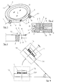
- a lens 1 is as optical element stored in an inner frame 2, which over three solid joints 3 distributed over the circumference is connected to an outer socket 4.
- Figure 2 shows a Solid-state joint in a T-shape, with the T-beam 5 on the Top is located and runs horizontally while the T-pillar 6 runs vertically.
- the solid-state joints 3 only approximately or in principle a T-shape, with connection points 7 and 8 between the inner frame 2 and the outer socket 4 at the outer ends of the T-beam 5 are located.
- a manipulator 9 In the area of the lower end of each T-pillar 6 attacks a manipulator 9, not shown, which in the outer socket 4 is mounted.
- a lever arm 10 of the manipulator 9 exerts tensile and / or compressive forces on the T-support 6 out.
- a lens is shown in principle in FIG. the in a lens or lens part 13 (only partially dashed shown) is installed, which in the installation position or later use of the center of gravity by the angle ⁇ differs.
- the lens 1 is not shown on a large number elastic feet 15 stored and thus gives a soft connection, resulting in a tilt like this is shown in the top view, namely the inclined position. By activating the corresponding manipulator (s) 9 this tilt can then be canceled or the lens 1 again return to their original reference position.
- FIG. 1 is only shown in principle how to e.g. by a capacitive sensor 16, which is in a recess 17 between the inner frame 2 and the outer frame 4 can determine the position.
- a capacitive sensor 16 which is in a recess 17 between the inner frame 2 and the outer frame 4 can determine the position.
Landscapes
- Physics & Mathematics (AREA)
- General Physics & Mathematics (AREA)
- Optics & Photonics (AREA)
- Lens Barrels (AREA)
- Exposure Of Semiconductors, Excluding Electron Or Ion Beam Exposure (AREA)
- Exposure And Positioning Against Photoresist Photosensitive Materials (AREA)
Abstract
Bei einer Vorrichtung zur Lagerung eines optischen Elementes (1) mit einer Innenfassung (2) und mit einer Außenfassung (4), insbesondere einer Linse in einem Projektionsobjektiv für die Halbleiter-Lithographie, ist die Innenfassung (2) mit der Außenfassung (4) über drei über den Umfang verteilt angeordnete Festkörpergelenke (3) verbunden. An den Festkörpergelenken (3) greifen Manipulatoren (9) an, durch die die Innenfassung (2) verschiebbar ist. Die Festkörpergelenke (3) weisen im Querschnitt gesehen wenigstens annähernd eine T-Form auf. Anbindungsstellen (7,8) zwischen der Innenfassung (2) und der Außenfassung (4) befinden sich jeweils im Bereich der äußeren Enden des T-Trägers (5). Die Manipulatoren (9) greifen jeweils an der T-Stütze (6) an. <IMAGE>In the case of a device for mounting an optical element (1) with an inner mount (2) and with an outer mount (4), in particular a lens in a projection lens for semiconductor lithography, the inner mount (2) with the outer mount (4) is over three solid joints (3) distributed over the circumference connected. Manipulators (9), through which the inner frame (2) can be displaced, act on the solid-state joints (3). The solid-state joints (3) have at least approximately a T-shape when viewed in cross section. Connection points (7,8) between the inner frame (2) and the outer frame (4) are located in the area of the outer ends of the T-beam (5). The manipulators (9) each engage the T-support (6). <IMAGE>
Description
Die Erfindung betrifft eine Vorrichtung zur Lagerung eines optischen
Elementes nach der im Oberbegriff von Anspruch 1 näher
definierten Art.The invention relates to a device for mounting an optical
Element according to the preamble of
Optische Elemente, wie z.B. Linsen, sind insbesondere in Objektiven für die Halbleiter-Lithographie bezüglich ihrer mechanischen Referenz sehr genau zu montieren und zu justieren. So ist z.B. bei Linsen die optische Achse mit der ideellen mechanischen Achse möglichst genau zur Deckung zu bringen.Optical elements, such as Lenses are especially in lenses for semiconductor lithography with regard to its mechanical To assemble and adjust the reference very precisely. So is e.g. for lenses the optical axis with the ideal mechanical Align axis as closely as possible.
In der älteren Anmeldung P 199 08 554.4 der Anmelderin ist eine Dreipunkt-Lagerung über Festkörperdrehgelenke mit Festkörperübergängen bekannt, welche durch Manipulatoren verstellbar sind. Eine Dreipunkt-Lagerung ist auch aus der US-PS 3,917,385 bekannt.In the earlier application P 199 08 554.4 of the applicant is one Three-point support via solid-body swivel joints with solid-body transitions known which is adjustable by manipulators are. A three-point bearing is also known from US Pat. No. 3,917,385 known.
Der vorliegenden Erfindung liegt die Aufgabe zugrunde, die bisher bekannte Montage- und Justagelagerungstechnik durch eine integrierte feinabstimmende Funktionseinheit zu verbessern, um eine höhere Positioniergenauigkeit zu erreichen.The present invention is based on the object so far Known assembly and adjustment storage technology through a integrated fine-tuning functional unit to improve to achieve a higher positioning accuracy.
Erfindungsgemäß wird diese Aufgabe durch die im kennzeichnenden
Teil von Anspruch 1 genannten Merkmale gelöst.According to the invention, this task is characterized by
Part of
Das gefaßte optische Element wird durch die drei am Umfang angeordneten Anbindungsstellen statisch bestimmt gehalten. Durch eine Verstellung an den T-förmigen Übergängen der Festkörpergelenke läßt sich nun die Innenfassung des optischen Elementes am Umfang lokal absenken oder aufstellen. Wenn dabei an allen drei Übergängen die gleiche Kraft und die gleiche Verschiebungsrichtung an den T-Stützen aufgebracht wird, so wird das optische Element entlang seiner optischen Achse (z-Achse) verschoben. Durch unterschiedliche Kräfte bzw. Verschiebungen an den Anbindungen können Kippungen der optische Achse korrigiert bzw. eingestellt werden.The mounted optical element is arranged by the three on the circumference Connection points kept statically determined. By an adjustment at the T-shaped transitions of the solid joints can now the inner frame of the optical element on Lower or set up the scope locally. If doing all three Transitions have the same force and the same direction of displacement is applied to the T-supports, so the optical Element moved along its optical axis (z-axis). Due to different forces or displacements on the connections can correct or set tilting of the optical axis become.
Eine sehr vorteilhafte konstruktive Ausgestaltung zur Lagerung des optischen Elementes kann darin bestehen, daß die Innenfassung, die Außenfassung und die Festkörpergelenke einstückig ausgebildet sind, wobei die Abtrennung durch Trennschnitte erfolgt.A very advantageous design for storage of the optical element can consist in that the inner frame, the outer frame and the solid body joints in one piece are formed, the separation being carried out by separating cuts.
Die Trennschnitte können z.B. im Erodierverfahren hergestellt werden.The separating cuts can e.g. manufactured in the EDM process become.
Ein sehr vorteilhaftes Anwendungsgebiet für die erfindungsgemäße Vorrichtung liegt in Objektiven, in denen optische Elemente in ihrer Einbaulage von der Schwerachse, d.h. von der Vertikalen abweichen. In diesem Fall neigt nämlich das optische Element aufgrund seines Eigengewichtes dazu, insbesondere bei weichen Anbindungen, bezüglich der mechanischen Referenz zu verkippen. Über die erfindungsgemäße Vorrichtung läßt sich dann mittels z.B. von außen montierten bzw. zugänglichen Sensoren die abweichende Lage feststellen und dann das optische Element wieder in seine ursprüngliche Lage zurückstellen.A very advantageous field of application for the invention Device lies in lenses in which optical elements in their installation position from the axis of gravity, i.e. from the vertical differ. In this case, namely, the optical element tends due to its own weight, especially with soft ones Connections to tilt with respect to the mechanical reference. The device according to the invention can then be used e.g. externally mounted or accessible sensors determine the deviating position and then the optical element return to its original position.
Bei einer geeigneten Ausbildung bzw. Zugängigkeit der Manipulatoren, welche z.B. hydraulische oder pneumatische Betätigungsglieder aufweisen können, ebenso wie mechanische oder elektrische, kann die erfindungsgemäße Vorrichtung auch aktiv in der optischen Funktionsgruppe benutzt werden, um während des Betriebes auftretende Bildfehler verstellen zu können.With a suitable training or accessibility of the manipulators, which e.g. hydraulic or pneumatic actuators can have, as well as mechanical or electrical, can the device according to the invention also actively in the optical function group used to during operation to be able to adjust occurring image errors.
Nachfolgend ist ein Ausführungsbeispiel der Erfindung anhand der Zeichnung prinzipmäßig beschrieben.An exemplary embodiment of the invention is described below described in principle of the drawing.
Es zeigt:
Figur 1- eine Prinzipdarstellung der Dreipunkt-Lagerung mit den erfindungsgemäßen Festkörpergelenken in perspektivischer Darstellung;
Figur 2- ausschnittsweise eine vergrößerte Darstellung eines Festkörpergelenkes in T-Form im Schnitt;
Figur 3- eine Prinzipdarstellung der Kraftwirkung zur Verstellung; und
Figur 4- eine Prinzipdarstellung eines optischen Elementes in einer von der Schwerachse abweichenden Einbaulage.
- Figure 1
- a schematic representation of the three-point bearing with the solid joints according to the invention in a perspective view;
- Figure 2
- sections of an enlarged view of a solid-state joint in a T-shape in section;
- Figure 3
- a schematic diagram of the force effect for adjustment; and
- Figure 4
- a schematic diagram of an optical element in an installation position deviating from the axis of gravity.
Gemäß Darstellung in den Figuren 1 und 2 ist eine Linse 1 als
optisches Element in einer Innenfassung 2 gelagert, welche über
drei über den Umfang verteilt angeordnete Festkörpergelenke 3
mit einer Außenfassung 4 verbunden ist. Aus Übersichtlichkeitsgründen
ist in der Figur 1 die Außenfassung 4 nur an den Anbindungsstellen
angedeutet. Darüber hinaus zeigt die Figur 2 ein
Festkörpergelenk in T-Form, wobei sich der T-Träger 5 auf der
Oberseite befindet und horizontal verläuft, während die T-Stütze
6 vertikal verläuft. In der Figur 1 hingegen ist die
umgekehrte Lage dargestellt. Wie ersichtlich, stellen die Festkörpergelenke
3 nur annähernd bzw. im Prinzip eine T-Form dar,
wobei sich Anbindungsstellen 7 und 8 zwischen der Innenfassung
2 und der Außenfassung 4 jeweils an den äußeren Enden des T-Trägers
5 befinden. Im Bereich des unteren Endes jeder T-Stütze
6 greift ein nicht näher dargestellter Manipulator 9 an, der in
der Außenfassung 4 gelagert ist. Ein Hebelarm 10 des Manipulators
9 übt dabei Zug- und/oder Druckkräfte auf die T-Stütze 6
aus.As shown in Figures 1 and 2, a
Wie aus der Kraftdarstellung der Figur 3 ersichtlich ist, wirkt
sich eine Kraft auf die T-Stütze 6 in Betätigungsrichtung 11
aufgrund der Kinematik der T-Form in eine Verschieberichtung in
Pfeilrichtung 12 der Innenfassung 2 aus. Auf diese Weise läßt
sich die Innenfassung 2 und damit auch die Linse 1 jeweils lokal
an der entsprechenden Anbindungsstelle absenken oder aufstellen,
wodurch die Linse 1 bezüglich ihrer optischen Achse
entsprechend gekippt wird. Wird an allen drei Festkörpergelenken
3 die gleiche Kraft bzw. Verschiebung aufgebracht, wird die
Linse 1 entlang ihrer optischen Achse verschoben.As can be seen from the force representation in FIG. 3, acts
a force on the T-
In der Figur 4 ist in Prinzipdarstellung eine Linse gezeigt,
die in ein Objektiv bzw. Objektivteil 13 (nur teilweise gestrichelt
dargestellt) eingebaut ist, welches in der Einbaulage
bzw. späteren Benutzung von der Schwerachse um den Winkel β
abweicht. Die Linse 1 ist auf einer Vielzahl nicht näher dargestellten
elastischen Füßchen 15 gelagert und ergibt damit eine
weiche Anbindung, woraus eine Verkippung resultiert, wie dies
in der oberen Ansicht, nämlich der Schräglage, dargestellt ist.
Durch Aktivierung des oder der entsprechenden Manipulatoren 9
läßt sich dann diese Verkippung aufheben bzw. die Linse 1 wieder
in ihre ursprüngliche Referenzlage zurückstellen.A lens is shown in principle in FIG.
the in a lens or lens part 13 (only partially dashed
shown) is installed, which in the installation position
or later use of the center of gravity by the angle β
differs. The
Aus der Figur 2 ist auch ersichtlich, daß die Abtrennung zwischen
der Innenfassung 2 und der Außenfassung 4 mit den dazwischen
liegenden Festkörpergelenken 3 durch Trennschnitte 14
erfolgt ist, so daß die gesamte Vorrichtung einstückig aufgebaut
ist.From Figure 2 it can also be seen that the separation between
the
In der Figur 1 ist lediglich prinzipmäßig dargestellt, wie man
z.B. durch einen kapazitiven Sensor 16, der sich in einer Aussparung
17 zwischen der Innenfassung 2 und der Außenfassung 4
befinden kann, Lagebestimmungen vornehmen kann. Hierfür sind
selbstverständlich mehrere kapazitive Sensoren 16, entsprechend
über den Umfang verteilt angeordnet, erforderlich.In Figure 1 is only shown in principle how to
e.g. by a
Claims (10)
Applications Claiming Priority (2)
| Application Number | Priority Date | Filing Date | Title |
|---|---|---|---|
| DE10051706A DE10051706A1 (en) | 2000-10-18 | 2000-10-18 | Device for supporting optical element, has approximately T-shaped joints with connection points between holders at outer ends of T-bearer and manipulators engaging T-support |
| DE10051706 | 2000-10-18 |
Publications (3)
| Publication Number | Publication Date |
|---|---|
| EP1209501A2 true EP1209501A2 (en) | 2002-05-29 |
| EP1209501A3 EP1209501A3 (en) | 2003-08-27 |
| EP1209501B1 EP1209501B1 (en) | 2005-11-23 |
Family
ID=7660240
Family Applications (1)
| Application Number | Title | Priority Date | Filing Date |
|---|---|---|---|
| EP01118867A Expired - Lifetime EP1209501B1 (en) | 2000-10-18 | 2001-08-16 | Apparatus for mounting an optical element |
Country Status (4)
| Country | Link |
|---|---|
| US (1) | US6580570B2 (en) |
| EP (1) | EP1209501B1 (en) |
| JP (1) | JP4146632B2 (en) |
| DE (2) | DE10051706A1 (en) |
Cited By (2)
| Publication number | Priority date | Publication date | Assignee | Title |
|---|---|---|---|---|
| WO2003016976A2 (en) * | 2001-08-18 | 2003-02-27 | Carl Zeiss Smt Ag | Device for adjusting an optical element |
| CN113167983A (en) * | 2018-11-29 | 2021-07-23 | 卡尔蔡司Smt有限责任公司 | Module for a projection exposure apparatus for semiconductor lithography with a semi-active spacer and method for using the semi-active spacer |
Families Citing this family (30)
| Publication number | Priority date | Publication date | Assignee | Title |
|---|---|---|---|---|
| DE10030495A1 (en) * | 2000-06-21 | 2002-01-03 | Zeiss Carl | Method for connecting a plurality of optical elements to a base body |
| DE10136387A1 (en) * | 2001-07-26 | 2003-02-13 | Zeiss Carl | Optical objective for semiconductor lithography has optical element with reflective reference surface used for adjustment relative to objective |
| DE10216114A1 (en) * | 2002-04-12 | 2003-10-23 | Zeiss Carl Smt Ag | Device for deformation-free mounting of non-rotation symmetrical optical elements has joining elements giving at least 1, maximum 2 degrees of translational freedom, 2 degrees of rotational freedom |
| DE10219514A1 (en) * | 2002-04-30 | 2003-11-13 | Zeiss Carl Smt Ag | Lighting system, especially for EUV lithography |
| WO2003102529A1 (en) | 2002-06-04 | 2003-12-11 | Nikon Corporation | Method of evaluating refractive index homogeneity of opical member |
| RU2005102099A (en) * | 2002-06-28 | 2005-09-10 | Карл Цайс Аг (De) | METHOD FOR CENTERING OPTICAL ELEMENTS AND DEVICE FOR ITS IMPLEMENTATION |
| DE10229623A1 (en) * | 2002-06-28 | 2004-01-15 | Carl Zeiss Jena Gmbh | Lens holder used in lithography for wafer inspection has an external fastening and inner optical element with elastomeric vibration damper between outer and inner sections |
| JP2005534998A (en) * | 2002-08-08 | 2005-11-17 | カール・ツァイス・エスエムティー・アーゲー | Apparatus for holding an optical assembly in an imaging device |
| DE10246828A1 (en) * | 2002-10-08 | 2004-04-22 | Carl Zeiss Smt Ag | Objective, in particular projection objective for microlithography used in the manufacture of semiconductor components has one housing for optical elements provided with mating surfaces |
| DE10331390A1 (en) * | 2003-07-11 | 2005-01-27 | Carl Zeiss Smt Ag | Aspherical surface production process for optical elements, comprises placing element in mould, introducing medium, and spherically working deformed optical medium |
| DE10339362A1 (en) | 2003-08-27 | 2005-03-24 | Carl Zeiss Smt Ag | Device for preventing the creeping of an optical element |
| US6816325B1 (en) | 2003-09-11 | 2004-11-09 | Carl Zeiss Smt Ag | Mounting apparatus for an optical element |
| DE10344178B4 (en) * | 2003-09-24 | 2006-08-10 | Carl Zeiss Smt Ag | Holding and positioning device for an optical element |
| US7085080B2 (en) * | 2003-12-06 | 2006-08-01 | Carl Zeiss Smt Ag | Low-deformation support device of an optical element |
| DE10359576A1 (en) * | 2003-12-18 | 2005-07-28 | Carl Zeiss Smt Ag | Method for producing an optical unit |
| US7265917B2 (en) | 2003-12-23 | 2007-09-04 | Carl Zeiss Smt Ag | Replacement apparatus for an optical element |
| JP4532545B2 (en) | 2004-06-29 | 2010-08-25 | カール・ツァイス・エスエムティー・アーゲー | Positioning unit and adjusting device for optical elements |
| DE102004052155A1 (en) * | 2004-10-24 | 2006-05-04 | Berliner Elektronenspeicherring-Gesellschaft für Synchrotronstrahlung mbH | Adjusting device for highly accurate positioning of an object |
| DE102005015627A1 (en) * | 2005-04-06 | 2006-10-12 | Carl Zeiss Smt Ag | Optical imaging device |
| DE102007030579B4 (en) * | 2006-07-21 | 2008-10-02 | Jenoptik Laser, Optik, Systeme Gmbh | Lateral adjustable socket for optical elements |
| DE102007005203A1 (en) | 2007-01-29 | 2008-07-31 | Carl Zeiss Smt Ag | Holder for optical element and for use with lithography objective, has actuator for indirectly moving optical element, where actuator is formed as bimorphes, piezoelectric element, and optical element takes up inner ring and outer ring |
| DE102008041310A1 (en) | 2007-08-31 | 2009-03-05 | Carl Zeiss Smt Ag | Optical element e.g. lens, for projection illumination system, has damping unit with sensor element detecting movement of element, and actuator element damping element by producing force or moment based on movement of element |
| WO2009110963A2 (en) * | 2008-02-29 | 2009-09-11 | Corning Incorporated | Kinematic optical mount |
| DE102008000967B4 (en) * | 2008-04-03 | 2015-04-09 | Carl Zeiss Smt Gmbh | Projection exposure machine for EUV microlithography |
| DE102008029161B3 (en) | 2008-06-19 | 2009-10-08 | Jenoptik Laser, Optik, Systeme Gmbh | Lateral adjustable optical socket with toggle manipulator units |
| DE102008063223B3 (en) | 2008-12-23 | 2010-09-09 | Jenoptik Laser, Optik, Systeme Gmbh | Monolithic optical socket |
| DE102009014972A1 (en) * | 2009-03-18 | 2010-10-14 | Carl Zeiss Laser Optics Gmbh | Optical device, has mounting bar fixed in optical axis, optical element fixed at symmetrical axis that is perpendicular to optical axis, and cross point in line with movement axes of bearing |
| CN102565983B (en) * | 2011-11-18 | 2014-08-20 | 中国科学院光电技术研究所 | Axial fine adjustment device for movable mirror |
| CN102621651B (en) * | 2012-03-29 | 2014-01-15 | 中国科学院光电技术研究所 | Micro-adjustment method for moving mirror |
| DE102018207454A1 (en) * | 2018-05-15 | 2019-05-29 | Carl Zeiss Smt Gmbh | Actuator assembly, projection exposure system and wafer inspection system for semiconductor lithography |
Citations (4)
| Publication number | Priority date | Publication date | Assignee | Title |
|---|---|---|---|---|
| DE19859634A1 (en) * | 1998-12-23 | 2000-06-29 | Zeiss Carl Fa | Optical system, in particular projection exposure system for microlithography |
| DE19905779A1 (en) * | 1999-02-12 | 2000-08-17 | Zeiss Carl Fa | Device for tilting an object around at least one axis, in particular an optical element |
| DE19908554A1 (en) * | 1999-02-27 | 2000-08-31 | Zeiss Carl Fa | Adjustable assembly |
| DE19910947A1 (en) * | 1999-03-12 | 2000-09-14 | Zeiss Carl Fa | Device for moving an optical element along the optical axis |
Family Cites Families (3)
| Publication number | Priority date | Publication date | Assignee | Title |
|---|---|---|---|---|
| US3917385A (en) | 1973-09-19 | 1975-11-04 | Rockwell International Corp | Simplified micropositioner |
| DE10026541A1 (en) * | 2000-05-27 | 2001-11-29 | Zeiss Carl | Device for the precise positioning of a component, in particular an optical component |
| DE10030005A1 (en) * | 2000-06-17 | 2001-12-20 | Zeiss Carl | Objective, in particular a projection objective in semiconductor lithography |
-
2000
- 2000-10-18 DE DE10051706A patent/DE10051706A1/en not_active Withdrawn
-
2001
- 2001-08-16 EP EP01118867A patent/EP1209501B1/en not_active Expired - Lifetime
- 2001-08-16 DE DE50108155T patent/DE50108155D1/en not_active Expired - Fee Related
- 2001-10-16 JP JP2001318392A patent/JP4146632B2/en not_active Expired - Fee Related
- 2001-10-18 US US10/002,097 patent/US6580570B2/en not_active Expired - Lifetime
Patent Citations (4)
| Publication number | Priority date | Publication date | Assignee | Title |
|---|---|---|---|---|
| DE19859634A1 (en) * | 1998-12-23 | 2000-06-29 | Zeiss Carl Fa | Optical system, in particular projection exposure system for microlithography |
| DE19905779A1 (en) * | 1999-02-12 | 2000-08-17 | Zeiss Carl Fa | Device for tilting an object around at least one axis, in particular an optical element |
| DE19908554A1 (en) * | 1999-02-27 | 2000-08-31 | Zeiss Carl Fa | Adjustable assembly |
| DE19910947A1 (en) * | 1999-03-12 | 2000-09-14 | Zeiss Carl Fa | Device for moving an optical element along the optical axis |
Cited By (7)
| Publication number | Priority date | Publication date | Assignee | Title |
|---|---|---|---|---|
| WO2003016976A2 (en) * | 2001-08-18 | 2003-02-27 | Carl Zeiss Smt Ag | Device for adjusting an optical element |
| WO2003016976A3 (en) * | 2001-08-18 | 2003-11-20 | Zeiss Carl Smt Ag | Device for adjusting an optical element |
| US7193794B2 (en) | 2001-08-18 | 2007-03-20 | Carl Zeiss Smt Ag | Adjustment arrangement of an optical element |
| US7457059B2 (en) | 2001-08-18 | 2008-11-25 | Carl Zeiss Smt Ag | Adjustment arrangement of an optical element |
| US7656595B2 (en) | 2001-08-18 | 2010-02-02 | Carl Zeiss Smt Ag | Adjustment arrangement of an optical element |
| CN113167983A (en) * | 2018-11-29 | 2021-07-23 | 卡尔蔡司Smt有限责任公司 | Module for a projection exposure apparatus for semiconductor lithography with a semi-active spacer and method for using the semi-active spacer |
| CN113167983B (en) * | 2018-11-29 | 2023-12-26 | 卡尔蔡司Smt有限责任公司 | Module for a projection exposure apparatus with semi-active spacers for semiconductor lithography and method for using the semi-active spacers |
Also Published As
| Publication number | Publication date |
|---|---|
| JP2002139661A (en) | 2002-05-17 |
| DE50108155D1 (en) | 2005-12-29 |
| DE10051706A1 (en) | 2002-05-02 |
| US20020085292A1 (en) | 2002-07-04 |
| JP4146632B2 (en) | 2008-09-10 |
| EP1209501A3 (en) | 2003-08-27 |
| US6580570B2 (en) | 2003-06-17 |
| EP1209501B1 (en) | 2005-11-23 |
Similar Documents
| Publication | Publication Date | Title |
|---|---|---|
| EP1209501A2 (en) | Apparatus for mounting an optical element | |
| EP1014139B1 (en) | Optical system, especially for a projection exposure system for microlithography, having a optical mount comprising actuators | |
| DE19910947A1 (en) | Device for moving an optical element along the optical axis | |
| EP1245982A2 (en) | Apparatus for holding an optical element in an optical device | |
| EP3310616B1 (en) | Vehicle headlamp with adjustable optical modules | |
| AT516100B1 (en) | Adjustment system for a vehicle headlight and vehicle headlights | |
| DE29907533U1 (en) | Device, in particular a work table for a projector | |
| DE3028899C2 (en) | ||
| DE10100546A1 (en) | Device for adjusting an optical element in a lens | |
| DE4208229A1 (en) | ADJUSTABLE TELESCOPIC MIRROR | |
| WO2003081337A2 (en) | Device for manipulation of the angular position of an object relative to a fixed structure | |
| DE102006044469A1 (en) | Device for vibration-free mounting of a spindle in a stand of a surgical microscope | |
| DE2716732A1 (en) | DEVICE FOR INSPECTING THE INTERNAL AND EXTERNAL SURFACES OF MECHANICAL PIECES AND ITS USE | |
| DE3436886C2 (en) | ||
| DE102006034455A1 (en) | Positionable workpiece support for a machine and processing system with a corresponding workpiece support | |
| DE10309859A1 (en) | Angle positioning | |
| EP0111215B1 (en) | Apparatus for the three-dimensional recording of the relative movements between a first and a second body | |
| DE102013114822B3 (en) | Two-axis tilting device | |
| DE2712516A1 (en) | SUPPORT AND ADJUSTMENT MECHANISM OF A ZOOM LENS | |
| DE8706688U1 (en) | Device for the calibration of tubular film bubbles | |
| DE2723323C3 (en) | Stereo photogrammetric evaluation device | |
| DE102006044688A1 (en) | Device for vibration-free mounting of a drive motor in a stand of a surgical microscope | |
| DE10136388A1 (en) | Measurement system for the correct assembly of an objective lens system, for use in semiconductor lithography, has a tactile position measurement element and an angular measurement element with a common reference plane | |
| DE102008053227A1 (en) | Piston/cylinder unit fastening arrangement for pneumatic and/or hydraulic compensation of weight-force of sleeve of e.g. coordinate measuring device, has compensation device held on support structure and/or connected with support structure | |
| DE102019102602A1 (en) | Optical assembly with an optical mount and a strip optic |
Legal Events
| Date | Code | Title | Description |
|---|---|---|---|
| PUAI | Public reference made under article 153(3) epc to a published international application that has entered the european phase |
Free format text: ORIGINAL CODE: 0009012 |
|
| AK | Designated contracting states |
Kind code of ref document: A2 Designated state(s): AT BE CH CY DE DK ES FI FR GB GR IE IT LI LU MC NL PT SE TR |
|
| AX | Request for extension of the european patent |
Free format text: AL;LT;LV;MK;RO;SI |
|
| PUAL | Search report despatched |
Free format text: ORIGINAL CODE: 0009013 |
|
| AK | Designated contracting states |
Designated state(s): AT BE CH CY DE DK ES FI FR GB GR IE IT LI LU MC NL PT SE TR |
|
| AX | Request for extension of the european patent |
Extension state: AL LT LV MK RO SI |
|
| RIC1 | Information provided on ipc code assigned before grant |
Ipc: 7G 02B 7/02 A Ipc: 7G 02B 7/00 B Ipc: 7G 03F 7/20 B |
|
| 17P | Request for examination filed |
Effective date: 20031024 |
|
| 17Q | First examination report despatched |
Effective date: 20040209 |
|
| AKX | Designation fees paid |
Designated state(s): DE FR NL |
|
| RAP1 | Party data changed (applicant data changed or rights of an application transferred) |
Owner name: CARL ZEISS SMT AG |
|
| GRAP | Despatch of communication of intention to grant a patent |
Free format text: ORIGINAL CODE: EPIDOSNIGR1 |
|
| GRAS | Grant fee paid |
Free format text: ORIGINAL CODE: EPIDOSNIGR3 |
|
| GRAA | (expected) grant |
Free format text: ORIGINAL CODE: 0009210 |
|
| AK | Designated contracting states |
Kind code of ref document: B1 Designated state(s): DE FR NL |
|
| PG25 | Lapsed in a contracting state [announced via postgrant information from national office to epo] |
Ref country code: NL Free format text: LAPSE BECAUSE OF FAILURE TO SUBMIT A TRANSLATION OF THE DESCRIPTION OR TO PAY THE FEE WITHIN THE PRESCRIBED TIME-LIMIT Effective date: 20051123 |
|
| REF | Corresponds to: |
Ref document number: 50108155 Country of ref document: DE Date of ref document: 20051229 Kind code of ref document: P |
|
| NLV1 | Nl: lapsed or annulled due to failure to fulfill the requirements of art. 29p and 29m of the patents act | ||
| PLBE | No opposition filed within time limit |
Free format text: ORIGINAL CODE: 0009261 |
|
| STAA | Information on the status of an ep patent application or granted ep patent |
Free format text: STATUS: NO OPPOSITION FILED WITHIN TIME LIMIT |
|
| PG25 | Lapsed in a contracting state [announced via postgrant information from national office to epo] |
Ref country code: FR Free format text: LAPSE BECAUSE OF FAILURE TO SUBMIT A TRANSLATION OF THE DESCRIPTION OR TO PAY THE FEE WITHIN THE PRESCRIBED TIME-LIMIT Effective date: 20061020 |
|
| 26N | No opposition filed |
Effective date: 20060824 |
|
| EN | Fr: translation not filed | ||
| PGFP | Annual fee paid to national office [announced via postgrant information from national office to epo] |
Ref country code: DE Payment date: 20080822 Year of fee payment: 8 |
|
| PG25 | Lapsed in a contracting state [announced via postgrant information from national office to epo] |
Ref country code: FR Free format text: LAPSE BECAUSE OF FAILURE TO SUBMIT A TRANSLATION OF THE DESCRIPTION OR TO PAY THE FEE WITHIN THE PRESCRIBED TIME-LIMIT Effective date: 20051123 |
|
| PG25 | Lapsed in a contracting state [announced via postgrant information from national office to epo] |
Ref country code: DE Free format text: LAPSE BECAUSE OF NON-PAYMENT OF DUE FEES Effective date: 20100302 |