EP1209054A2 - Reservoir arrangement and auxiliary reservoir - Google Patents
Reservoir arrangement and auxiliary reservoir Download PDFInfo
- Publication number
- EP1209054A2 EP1209054A2 EP01309033A EP01309033A EP1209054A2 EP 1209054 A2 EP1209054 A2 EP 1209054A2 EP 01309033 A EP01309033 A EP 01309033A EP 01309033 A EP01309033 A EP 01309033A EP 1209054 A2 EP1209054 A2 EP 1209054A2
- Authority
- EP
- European Patent Office
- Prior art keywords
- reservoir
- working fluid
- opening portion
- main body
- auxiliary reservoir
- Prior art date
- Legal status (The legal status is an assumption and is not a legal conclusion. Google has not performed a legal analysis and makes no representation as to the accuracy of the status listed.)
- Granted
Links
- 239000012530 fluid Substances 0.000 claims abstract description 61
- 230000015572 biosynthetic process Effects 0.000 claims abstract description 3
- 210000002445 nipple Anatomy 0.000 claims description 5
- 229920003002 synthetic resin Polymers 0.000 claims description 2
- 239000000057 synthetic resin Substances 0.000 claims description 2
- 238000000034 method Methods 0.000 abstract description 11
- 239000000344 soap Substances 0.000 description 4
- 230000000694 effects Effects 0.000 description 2
- 230000002708 enhancing effect Effects 0.000 description 2
- 230000029058 respiratory gaseous exchange Effects 0.000 description 2
- 238000004891 communication Methods 0.000 description 1
- 238000002474 experimental method Methods 0.000 description 1
- 239000007788 liquid Substances 0.000 description 1
- 239000000463 material Substances 0.000 description 1
- 238000000465 moulding Methods 0.000 description 1
- 238000005192 partition Methods 0.000 description 1
- 238000003466 welding Methods 0.000 description 1
Images

Classifications
-
- B—PERFORMING OPERATIONS; TRANSPORTING
- B60—VEHICLES IN GENERAL
- B60T—VEHICLE BRAKE CONTROL SYSTEMS OR PARTS THEREOF; BRAKE CONTROL SYSTEMS OR PARTS THEREOF, IN GENERAL; ARRANGEMENT OF BRAKING ELEMENTS ON VEHICLES IN GENERAL; PORTABLE DEVICES FOR PREVENTING UNWANTED MOVEMENT OF VEHICLES; VEHICLE MODIFICATIONS TO FACILITATE COOLING OF BRAKES
- B60T17/00—Component parts, details, or accessories of power brake systems not covered by groups B60T8/00, B60T13/00 or B60T15/00, or presenting other characteristic features
- B60T17/06—Applications or arrangements of reservoirs
-
- B—PERFORMING OPERATIONS; TRANSPORTING
- B60—VEHICLES IN GENERAL
- B60T—VEHICLE BRAKE CONTROL SYSTEMS OR PARTS THEREOF; BRAKE CONTROL SYSTEMS OR PARTS THEREOF, IN GENERAL; ARRANGEMENT OF BRAKING ELEMENTS ON VEHICLES IN GENERAL; PORTABLE DEVICES FOR PREVENTING UNWANTED MOVEMENT OF VEHICLES; VEHICLE MODIFICATIONS TO FACILITATE COOLING OF BRAKES
- B60T11/00—Transmitting braking action from initiating means to ultimate brake actuator without power assistance or drive or where such assistance or drive is irrelevant
- B60T11/10—Transmitting braking action from initiating means to ultimate brake actuator without power assistance or drive or where such assistance or drive is irrelevant transmitting by fluid means, e.g. hydraulic
- B60T11/26—Reservoirs
Definitions
- This invention relates to a reservoir technique for supplying a working fluid to a master cylinder of vehicles, and more particularly to a reservoir of the type which comprises an auxiliary reservoir located proximal or close to a master cylinder and a main reservoir having a hydraulic fluid inlet opening and connected to the auxiliary reservoir through a piping.
- a master cylinder of vehicles essentially requires a working fluid for operating the braking system, etc. It is the reservoir apparatus which stores the working fluid. Experience teaches that work is also necessary for supplying a working fluid to the reservoir apparatus or replacing the working fluid with new one.
- a reservoir apparatus which has been developed taking into consideration the replenishing work and replacing work of the working fluid and in which a hydraulic fluid inlet opening for the working fluid is arranged at a located where both the replenishing work and the replacing work can easily be made.
- a microfilm first example of the related art
- Japanese Utility Model Application No. S56-14365 Japanese Utility Model Application Unexamined Publication No. S58-48555
- the reservoir apparatus is divided into an auxiliary reservoir and a main reservoir, both of the reservoirs are connected to each other through a piping such as a hose or the like, and an inlet opening for feeding a hydraulic fluid is arranged at a location where it does not interfere other devices (in other words, at a location easy to work).
- This conventional invention is based on an idea that the auxiliary reservoir is arranged at a location proximal to a master cylinder so that a working fluid can be supplied to the master cylinder rapidly and smoothly, while the other main reservoir is provided with a hydraulic fluid inlet opening and arranged at a location where a hydraulic fluid can easily be supplied therein.
- the incompatible requirements for installing the master cylinder in a limited space together with other devices and for enabling the replenishment or replacement of the working fluid with ease can be satisfied at the same time.
- the connecting portion of the piping on the auxiliary reservoir side located proximate to the master cylinder is disposed in an upright posture on an upper part of the auxiliary reservoir.
- the height of the auxiliary reservoir on the master cylinder becomes high as a whole and the mounting space of the master cylinder with the auxiliary reservoir attached thereto becomes large.
- the connecting portion of the piping is, as disclosed in Japanese Utility Model Publication No. H08-2007 (second example of the related art), preferably slanted with respect to a direction of the height of the auxiliary reservoir.
- the inventor of the present invention paid attention to the technique for diagonally drawing out the connecting portion of the pining or the connecting pipe for connecting the piping from the upper part of the auxiliary reservoir and carried out an extensive experiment and study about replenishment property of the working fluid into the auxiliary reservoir.
- a film of the working fluid is formed at an opening portion of the connecting pipe which faces the inside of the auxiliary reservoir at the time of replenishment and therefore, there is such a risk that the film jeopardizes the replenishment property of the working fluid.
- the replenishment of the working fluid into the auxiliary reservoir is conducted in such a manner that the working fluid is supplied from the hydraulic fluid inlet port of the main reservoir and replaced with air in the auxiliary reservoir through the piping.
- the air in the auxiliary reservoir i.e., air to be replaced with the working fluid
- the inside of the auxiliary reservoir is evacuated or reduced in pressure, i.e., the method of vacuum breathing is applied.
- the method for vacuum breathing it is required for vacuum breathing to employ extra equipment such as a vacuum pump and in addition, the operation is troublesome.
- the method for replacing the atmospheric air on the auxiliary reservoir side with the working fluid from the main reservoir side does not require extra devices and the operation is easy.
- an object of the present invention to provide a technique capable of replenishing a working fluid smoothly while employing a method for replacing an atmospheric air with the working fluid.
- the working fluid which flows into the auxiliary reservoir from an opening portion of a connecting pipe is affected by the air flowing from the auxiliary reservoir side towards the main reservoir side (flow reverse to the flow of the working fluid).
- the air forms a film, i.e., the so-called “soap bubble", covering the opening portion using the viscous working fluid as a "soap bubble liquid”.
- the basis of this invention for solving the problems is to provide a constitution in which the film, i.e., "soap bubble" covering the opening portion, is difficult to be formed.
- the connecting pipe is provided at its opening portion with a recessed portion and/or protruded portion for changing the configuration of the opening portion.
- the recessed portion and/or protruded portion used herein refers to a) only recessed portion but the number of the recessed portion is not limited to one, b) only protruded portion but the number of the protruded portion is not limited to one, and c) a combination of a) and b).
- the auxiliary reservoir including the connecting pipe is usually a molded article from synthetic resin. The recessed portion and/or protruded portion can easily be formed by molding.
- the form for preventing the generation of the film which covers the opening portion is preferably a recessed portion disposed at a lower side of the opening portion, and particularly preferably a recessed portion extending downward when viewed in a direction of the height of the auxiliary reservoir, one end of the recessed portion being connected to the inner side of the connecting pipe and the other end of the recessed portion being extended along the inner wall of the auxiliary reservoir from the opening portion and reaching the lower part.
- the recessed portion of this case has the function for enlarging the size of the opening portion and enhancing a more smooth flow of the replenishment working fluid at the nearby area of the opening portion when compared with a case where there is no such recessed portion.
- the opening portion of the connecting pipe is more enlarged even at the time for replenishment of the working fluid thereby preventing the generation of the film of the working fluid.
- the protruded portion is preferably disposed at an upper part of the opening portion.
- the protruded portion has the function for defining a plurality of passageways at the upper part of the opening portion thereby dividing the flow of air from the flow of working fluid. Owing to this function of the protruded portion, it can be considered that the effect of the flow of air to be prevailed on the replenishment working fluid becomes so small that no film of the working fluid is formed at the opening portion.
- the opening portion of the connecting pipe may be disposed in such a manner as to be orthogonal to a direction of the height of the auxiliary reservoir.
- the entire opening portion is located at the uppermost part of a reservoir space formed within the auxiliary reservoir. Consequence, as the replenishment working fluid fills the reservoir space in the auxiliary reservoir, the entire opening portion is choked with the working fluid almost at the same time (i.e., instantaneously) on the last stage of the filling operation. Accordingly, it can be consistently avoided that the size of the opening portion of the connecting pipe is gradually reduced. Since it is considered that the film covering the opening portion, i.e., the so-called "soap bubble" is generated in a state in which the size of the connecting pipe is gradually reduced, another form of the protruded portion as mentioned is also effective.
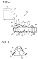
- FIG. 1 shows one embodiment of the present invention in which the present invention is applied to a reservoir apparatus for use of a tandem type master cylinder and in which an auxiliary reservoir portion is shown in a sectional view.
- a reservoir apparatus 10 as one embodiment of the present invention comprises a main reservoir 20 arranged at a location easy to conduct the replenishing operation, and an auxiliary reservoir 50 supported on a cylinder main body of a master cylinder not shown.
- the main reservoir 20 comprises a container main body 24 including a piping connecting portion 22, and a cap 26 for covering an upper opening of the container main body 24. By removing the cap 26, the upper opening of the container main body 24 can serve as an inlet opening for feeding a hydraulic fluid.
- a fluid surface detector means (not shown) including a float is received in the container main body 24 of the main reservoir 20, the capacity of the main reservoir 20 is larger than that of the auxiliary reservoir 50.
- the main reservoir 20 is arranged at a location higher than the auxiliary reservoir 50 so that a working fluid can normally be supplied to the auxiliary reservoir 50 through a piping 30 such as a hose or the like.
- the auxiliary reservoir 50 has a capacity large enough to fill the amount of fluid used for operation of a brake.
- the height of a container main body 54 is gradually lowered by about 2 to 3 cm.
- the container main body 54 is of two-split structure consisting of an upper half section 541 and a lower half section 542.
- the upper and lower half sections 541, 542 are integrally joined by heat welding.
- the upper half section 541 of the container main body 54 is provided at an upper part thereof with a connecting pipe 60 which diagonally runs with respect to a direction of the height of the auxiliary reservoir 50.
- the lower half section 542 is provided at a lower part thereof with two nipple portion 72, 74 extending in a direction of the height of the auxiliary reservoir 50.
- the connecting pipe 60 is a member for connecting an internal reservoir space 52 of the container main body 54 to the main reservoir 24 side through the piping 30.
- An end portion of the connecting pipe 60 on the side protruding outward serves as a piping connecting portion 62.
- a passage way formed at an inner periphery of the piping connecting portion 62 is in communication with the inside of the container main body 54 through an opening portion 64 formed at its end.
- the two nipple portions 72, 74 are adapted to connect the auxiliary reservoir 50 to a boss portion of the cylinder main body of the master cylinder.
- the interior of the container main body 54 more strictly that portion of the lower half section 542, is divided into two parts by a partition wall 55.
- the nipple portion 72 is located at one of the two parts, and the other nipple portion 74 is located at the other part. This arrangement is made for the purpose of ensuring the independency of two brake systems, namely, a primary brake system and a second brake system.
- the upper half section 541 of the container main body 54 is more protuberated at a part of the upper wall portion thereof than the rest portion, and only the protuberated portion includes a protuberant portion 58 for enlarging the reservoir space 52 to the extent of the protuberated portion.
- the protuberant portion 58 is gradually slanted upward from one side thereof towards the other side. That end of the protuberant portion 58 on the higher side is defined as a flattened surface where the opening portion 64 of the connecting pipe 60 is arranged.
- the opening portion 64 of the connecting pipe 60 is located at the uppermost part of the reservoir space 52 of the container main body 54.
- the inside diameter of the connecting pipe 60 is, for example, about 5 mm.
- the working fluid gradually fills the reservoir space 52 while pushing out the internal air of the auxiliary reservoir 50 through the main reservoir 24, the piping 30 and the connecting pipe 60.
- a film of the working fluid material tends to be formed at the opening portion 64.
- a recessed portion 80 is formed at a lower part of the opening portion 64 in this embodiment. The recessed portion 80 extends downward along a direction of the height of the auxiliary reservoir 50.
- One end of the recessed portion 80 is located at the inner periphery wall surface of the connecting pipe 60 and the other end reaches so far as to the inner wall of the upper half section 541.
- An inner wall portion 543 of the upper half section 541 where the recessed portion 80 is disposed is orthogonal to a direction of extension of the protuberant portion 58 and the connecting pipe 60 connected thereto.
- the inner wall portion 543 is slanted, for example, about 15 degrees (this angle is equal to the angle of inclination of the connecting pipe 60) with respect to the direction of the height of the auxiliary reservoir 50.
- the width of the groove-like recessed portion 80 is about 4 mm which is smaller than the inside diameter of the connecting pipe 60.
- FIGS. 1 and 2 While the one embodiment of the reservoir apparatus 10 has been specifically shown and described herein, the invention itself is not to be restricted by the exact showing of FIGS. 1 and 2 or the description thereof.
- the present invention can be applied to the reservoir apparatus in modified forms, such as a form having two recessed portions 80a, 80b separated by a central projection 90 (refer to FIG. 3A), a form having one protruded portion 800 disposed at an upper part of the opening portion 64 (refer to FIG. 3B), and a form having two protruded portions 800a, 800b disposed at an upper part of the opening portion 64 (refer to FIG. 3C).
- modified forms such as a form having two recessed portions 80a, 80b separated by a central projection 90 (refer to FIG. 3A), a form having one protruded portion 800 disposed at an upper part of the opening portion 64 (refer to FIG. 3B), and a form having two protruded portions 800a, 800b disposed at an upper part of the opening portion
Landscapes
- Engineering & Computer Science (AREA)
- Transportation (AREA)
- Mechanical Engineering (AREA)
- Transmission Of Braking Force In Braking Systems (AREA)
- Valves And Accessory Devices For Braking Systems (AREA)
Abstract
Description
- This invention relates to a reservoir technique for supplying a working fluid to a master cylinder of vehicles, and more particularly to a reservoir of the type which comprises an auxiliary reservoir located proximal or close to a master cylinder and a main reservoir having a hydraulic fluid inlet opening and connected to the auxiliary reservoir through a piping.
- A master cylinder of vehicles essentially requires a working fluid for operating the braking system, etc. It is the reservoir apparatus which stores the working fluid. Experience teaches that work is also necessary for supplying a working fluid to the reservoir apparatus or replacing the working fluid with new one.
- There is known a reservoir apparatus which has been developed taking into consideration the replenishing work and replacing work of the working fluid and in which a hydraulic fluid inlet opening for the working fluid is arranged at a located where both the replenishing work and the replacing work can easily be made. For example, as shown in a microfilm (first example of the related art) of Japanese Utility Model Application No. S56-14365 (Japanese Utility Model Application Unexamined Publication No. S58-48555), the reservoir apparatus is divided into an auxiliary reservoir and a main reservoir, both of the reservoirs are connected to each other through a piping such as a hose or the like, and an inlet opening for feeding a hydraulic fluid is arranged at a location where it does not interfere other devices (in other words, at a location easy to work). This conventional invention is based on an idea that the auxiliary reservoir is arranged at a location proximal to a master cylinder so that a working fluid can be supplied to the master cylinder rapidly and smoothly, while the other main reservoir is provided with a hydraulic fluid inlet opening and arranged at a location where a hydraulic fluid can easily be supplied therein. According to this idea, the incompatible requirements for installing the master cylinder in a limited space together with other devices and for enabling the replenishment or replacement of the working fluid with ease can be satisfied at the same time.
- According to the technique shown in the first example of the related art, the connecting portion of the piping on the auxiliary reservoir side located proximate to the master cylinder is disposed in an upright posture on an upper part of the auxiliary reservoir. However, in that form, the height of the auxiliary reservoir on the master cylinder becomes high as a whole and the mounting space of the master cylinder with the auxiliary reservoir attached thereto becomes large. In order to reduce the mounting space, the connecting portion of the piping is, as disclosed in Japanese Utility Model Publication No. H08-2007 (second example of the related art), preferably slanted with respect to a direction of the height of the auxiliary reservoir.
- The inventor of the present invention paid attention to the technique for diagonally drawing out the connecting portion of the pining or the connecting pipe for connecting the piping from the upper part of the auxiliary reservoir and carried out an extensive experiment and study about replenishment property of the working fluid into the auxiliary reservoir. As a result, he found out a fact that a film of the working fluid is formed at an opening portion of the connecting pipe which faces the inside of the auxiliary reservoir at the time of replenishment and therefore, there is such a risk that the film jeopardizes the replenishment property of the working fluid. Incidentally, the replenishment of the working fluid into the auxiliary reservoir is conducted in such a manner that the working fluid is supplied from the hydraulic fluid inlet port of the main reservoir and replaced with air in the auxiliary reservoir through the piping. Accordingly, when the working fluid flows from the main reservoir side towards the auxiliary reservoir side, the air in the auxiliary reservoir (i.e., air to be replaced with the working fluid) flows from the auxiliary reservoir side towards the main reservoir side. As a method for preventing the formation of the film which covers the opening portion, it can also be considered that the inside of the auxiliary reservoir is evacuated or reduced in pressure, i.e., the method of vacuum breathing is applied. However, it is required for vacuum breathing to employ extra equipment such as a vacuum pump and in addition, the operation is troublesome. In this respect, the method for replacing the atmospheric air on the auxiliary reservoir side with the working fluid from the main reservoir side does not require extra devices and the operation is easy.
- It is, therefore, an object of the present invention to provide a technique capable of replenishing a working fluid smoothly while employing a method for replacing an atmospheric air with the working fluid.
- It is another object of the present invention to provide a technique capable of enhancing the replenishment property of a working fluid merely by slightly changing the configuration or constitution of an auxiliary reservoir located proximal to a master cylinder.
- Other objects of the present invention will become more clear from the following description.
- When the air in an auxiliary reservoir is replaced with a working fluid, the working fluid which flows into the auxiliary reservoir from an opening portion of a connecting pipe is affected by the air flowing from the auxiliary reservoir side towards the main reservoir side (flow reverse to the flow of the working fluid). Probably, the air forms a film, i.e., the so-called "soap bubble", covering the opening portion using the viscous working fluid as a "soap bubble liquid". The basis of this invention for solving the problems is to provide a constitution in which the film, i.e., "soap bubble" covering the opening portion, is difficult to be formed.
- Based on such basis, according to this invention, the connecting pipe is provided at its opening portion with a recessed portion and/or protruded portion for changing the configuration of the opening portion. The recessed portion and/or protruded portion used herein refers to a) only recessed portion but the number of the recessed portion is not limited to one, b) only protruded portion but the number of the protruded portion is not limited to one, and c) a combination of a) and b). The auxiliary reservoir including the connecting pipe is usually a molded article from synthetic resin. The recessed portion and/or protruded portion can easily be formed by molding.
- The form for preventing the generation of the film which covers the opening portion is preferably a recessed portion disposed at a lower side of the opening portion, and particularly preferably a recessed portion extending downward when viewed in a direction of the height of the auxiliary reservoir, one end of the recessed portion being connected to the inner side of the connecting pipe and the other end of the recessed portion being extended along the inner wall of the auxiliary reservoir from the opening portion and reaching the lower part. The recessed portion of this case has the function for enlarging the size of the opening portion and enhancing a more smooth flow of the replenishment working fluid at the nearby area of the opening portion when compared with a case where there is no such recessed portion. Owing to this function of the recessed portion, it can be considered that the opening portion of the connecting pipe is more enlarged even at the time for replenishment of the working fluid thereby preventing the generation of the film of the working fluid. In contrast, the protruded portion is preferably disposed at an upper part of the opening portion. The protruded portion has the function for defining a plurality of passageways at the upper part of the opening portion thereby dividing the flow of air from the flow of working fluid. Owing to this function of the protruded portion, it can be considered that the effect of the flow of air to be prevailed on the replenishment working fluid becomes so small that no film of the working fluid is formed at the opening portion.
- As another form of the protruded portion, the opening portion of the connecting pipe may be disposed in such a manner as to be orthogonal to a direction of the height of the auxiliary reservoir. In that case, the entire opening portion is located at the uppermost part of a reservoir space formed within the auxiliary reservoir. Consequence, as the replenishment working fluid fills the reservoir space in the auxiliary reservoir, the entire opening portion is choked with the working fluid almost at the same time (i.e., instantaneously) on the last stage of the filling operation. Accordingly, it can be consistently avoided that the size of the opening portion of the connecting pipe is gradually reduced. Since it is considered that the film covering the opening portion, i.e., the so-called "soap bubble" is generated in a state in which the size of the connecting pipe is gradually reduced, another form of the protruded portion as mentioned is also effective.
- The invention will now be described further by way of example with reference to the accompanying drawings in which:-
- FIG. 1 is a view showing one embodiment of a reservoir apparatus to which the present invention is applied;
- FIG. 2 is a sectional view taken on line 2-2 and viewed in a direction as shown by arrows of FIG. 1; and
- FIG. 3A through 3C are similar views to FIG. 2, in which modified forms of the present invention are shown.
-
- FIG. 1 shows one embodiment of the present invention in which the present invention is applied to a reservoir apparatus for use of a tandem type master cylinder and in which an auxiliary reservoir portion is shown in a sectional view. A
reservoir apparatus 10 as one embodiment of the present invention comprises amain reservoir 20 arranged at a location easy to conduct the replenishing operation, and anauxiliary reservoir 50 supported on a cylinder main body of a master cylinder not shown. Themain reservoir 20 comprises a containermain body 24 including apiping connecting portion 22, and acap 26 for covering an upper opening of the containermain body 24. By removing thecap 26, the upper opening of the containermain body 24 can serve as an inlet opening for feeding a hydraulic fluid. Since a fluid surface detector means (not shown) including a float is received in the containermain body 24 of themain reservoir 20, the capacity of themain reservoir 20 is larger than that of theauxiliary reservoir 50. Themain reservoir 20 is arranged at a location higher than theauxiliary reservoir 50 so that a working fluid can normally be supplied to theauxiliary reservoir 50 through apiping 30 such as a hose or the like. - The
auxiliary reservoir 50 has a capacity large enough to fill the amount of fluid used for operation of a brake. The height of a containermain body 54 is gradually lowered by about 2 to 3 cm. The containermain body 54 is of two-split structure consisting of anupper half section 541 and a lower half section 542. The upper andlower half sections 541, 542 are integrally joined by heat welding. Theupper half section 541 of the containermain body 54 is provided at an upper part thereof with a connectingpipe 60 which diagonally runs with respect to a direction of the height of theauxiliary reservoir 50. On the other hand, the lower half section 542 is provided at a lower part thereof with twonipple portion auxiliary reservoir 50. The connectingpipe 60 is a member for connecting aninternal reservoir space 52 of the containermain body 54 to themain reservoir 24 side through thepiping 30. An end portion of the connectingpipe 60 on the side protruding outward serves as apiping connecting portion 62. A passage way formed at an inner periphery of thepiping connecting portion 62 is in communication with the inside of the containermain body 54 through anopening portion 64 formed at its end. The twonipple portions auxiliary reservoir 50 to a boss portion of the cylinder main body of the master cylinder. The interior of the containermain body 54, more strictly that portion of the lower half section 542, is divided into two parts by apartition wall 55. Thenipple portion 72 is located at one of the two parts, and theother nipple portion 74 is located at the other part. This arrangement is made for the purpose of ensuring the independency of two brake systems, namely, a primary brake system and a second brake system. - It is necessary to fill up the
reservoir space 52 in theauxiliary reservoir 50 with the working fluid. If not, air may mix therein and trouble is likely to occur to the braking operation. To this end, theupper half section 541 of the containermain body 54 is more protuberated at a part of the upper wall portion thereof than the rest portion, and only the protuberated portion includes aprotuberant portion 58 for enlarging thereservoir space 52 to the extent of the protuberated portion. Theprotuberant portion 58 is gradually slanted upward from one side thereof towards the other side. That end of theprotuberant portion 58 on the higher side is defined as a flattened surface where the openingportion 64 of the connectingpipe 60 is arranged. Accordingly, the openingportion 64 of the connectingpipe 60 is located at the uppermost part of thereservoir space 52 of the containermain body 54. The inside diameter of the connectingpipe 60 is, for example, about 5 mm. At the time for replenishing the interior of the containermain body 54 with the working fluid, the working fluid gradually fills thereservoir space 52 while pushing out the internal air of theauxiliary reservoir 50 through themain reservoir 24, the piping 30 and the connectingpipe 60. As previously mentioned, due to effect of the air to be replaced, a film of the working fluid material tends to be formed at the openingportion 64. In order to prevent the generation of the film, a recessedportion 80 is formed at a lower part of the openingportion 64 in this embodiment. The recessedportion 80 extends downward along a direction of the height of theauxiliary reservoir 50. One end of the recessedportion 80 is located at the inner periphery wall surface of the connectingpipe 60 and the other end reaches so far as to the inner wall of theupper half section 541. Aninner wall portion 543 of theupper half section 541 where the recessedportion 80 is disposed is orthogonal to a direction of extension of theprotuberant portion 58 and the connectingpipe 60 connected thereto. In other words, theinner wall portion 543 is slanted, for example, about 15 degrees (this angle is equal to the angle of inclination of the connecting pipe 60) with respect to the direction of the height of theauxiliary reservoir 50. The width of the groove-like recessedportion 80 is about 4 mm which is smaller than the inside diameter of the connectingpipe 60. - While the one embodiment of the
reservoir apparatus 10 has been specifically shown and described herein, the invention itself is not to be restricted by the exact showing of FIGS. 1 and 2 or the description thereof. The present invention can be applied to the reservoir apparatus in modified forms, such as a form having two recessedportions portion 800 disposed at an upper part of the opening portion 64 (refer to FIG. 3B), and a form having two protrudedportions
Claims (6)
- A reservoir apparatus (10) for supplying a working fluid to a master cylinder comprising an auxiliary reservoir (50) located proximate to said master cylinder, and a main reservoir (20) located more away from said master cylinder than said auxiliary reservoir (50), said main reservoir (20) having an inlet opening for feeding a hydraulic fluid and connected to said auxiliary reservoir (50) through a piping (30)
CHARACTERIZED in that said auxiliary reservoir (50) includes a container main body (54) defining therein a reservoir space (52) for containing a working fluid, and a connecting pipe (60) which is integral with said container main body (54) and runs diagonally with respect to a height direction thereof, one end of which is an opening portion (64) which is open at an uppermost part of said reservoir space (52) and the other end portion of which is protruded from said container main body (54) and serves as a connecting portion for said piping (30), said connecting pipe (60) is provided at said opening portion (64) with a recessed portion (80) and/or a protruded portion for changing the configuration of said opening portion (64), said recessed portion (80) and/or said protruded portion preventing the working fluid from forming a film which covers said opening portion (64) when air stayed within said reservoir space (52) is replaced with the working fluid. - A reservoir apparatus according to claim 1, wherein said container main body (54) is more protuberated at a part of a wall portion thereof than the rest portion, only said protuberated portion includes a protuberant portion (58) for enlarging said reservoir space (52), said protuberant portion (58) is gradually slanted upward from one side thereof towards the other side, and said opening portion (64) is located at the higher side of said slanted portion of said protuberant portion (58).
- A reservoir apparatus according to claim 2, wherein said protuberant portion (58) has a flattened surface where said opening portion (64) is situated, and said flattened surface is orthogonal to the slanting direction of said protuberant portion (58).
- An auxiliary reservoir of a small capacity attached to a master cylinder and through a piping (30) connected to a main reservoir (20) having an inlet opening for feeding a hydraulic fluid,
CHARACTERIZED in that said auxiliary reservoir (50) includes a container main body (54) defining therein a reservoir space (52) for containing a working fluid, and a connecting pipe (60) which is integral with said container main body (54) and which runs diagonally with respect to a height direction thereof, one end of which is an opening portion (64) which is open at an uppermost part of said reservoir space (52) and the other end portion of which is protruded from said container main body (54) and serves as a connecting portion (62) for said piping (30), said connecting pipe (60) is provided at said opening portion (64) with a recessed portion (80) and/or a protruded portion for changing the configuration of said opening portion (64), said recessed portion (80) and/or said protruded portion preventing the working fluid from forming a film which covers said opening portion (64) when air stayed within said reservoir space (52) is replaced with the working fluid. - An auxiliary reservoir according to claim 4, wherein said master cylinder is of tandem type, and said container main body (54) includes two nipple portions (72, 74) connected to said master cylinder side, and one connecting pipe (60) for connecting said piping (60).
- An auxiliary reservoir according to claim 4, wherein said container main body (54) is a molded article made from synthetic resin, and said opening portion (64) includes a recessed portion (80) extending downwards in a direction of a lower side, when viewed in a height direction of said auxiliary reservoir (50), to enlarge said opening portion (64) and having a function for preventing formation of a film which covers said opening portion (64).
Applications Claiming Priority (2)
| Application Number | Priority Date | Filing Date | Title |
|---|---|---|---|
| JP2000360643A JP4257886B2 (en) | 2000-11-28 | 2000-11-28 | Reservoir device and auxiliary reservoir |
| JP2000360643 | 2000-11-28 |
Publications (3)
| Publication Number | Publication Date |
|---|---|
| EP1209054A2 true EP1209054A2 (en) | 2002-05-29 |
| EP1209054A3 EP1209054A3 (en) | 2004-01-14 |
| EP1209054B1 EP1209054B1 (en) | 2006-06-14 |
Family
ID=18832205
Family Applications (1)
| Application Number | Title | Priority Date | Filing Date |
|---|---|---|---|
| EP01309033A Expired - Lifetime EP1209054B1 (en) | 2000-11-28 | 2001-10-24 | Reservoir arrangement and auxiliary reservoir |
Country Status (5)
| Country | Link |
|---|---|
| US (1) | US6550591B2 (en) |
| EP (1) | EP1209054B1 (en) |
| JP (1) | JP4257886B2 (en) |
| DE (1) | DE60120608T2 (en) |
| ES (1) | ES2266124T3 (en) |
Cited By (4)
| Publication number | Priority date | Publication date | Assignee | Title |
|---|---|---|---|---|
| DE10233350A1 (en) * | 2002-07-23 | 2004-02-12 | Wiesauplast Kunststoff Und Formenbau Gmbh & Co. Kg | Combination compensator reservoir for main cylinder consists of two containers connected via connection with two separate channels |
| FR2844239A1 (en) * | 2002-09-11 | 2004-03-12 | Bosch Gmbh Robert | Device for supplying hydraulic brake fluid from a master cylinder to a motor vehicle brake circuit includes top and bottom conduits interconnecting main fluid reservoir and intermediate reservoir |
| FR2874365A1 (en) * | 2004-08-19 | 2006-02-24 | Bosch Gmbh Robert | LINK DEVICE FOR BRAKE FLUID RESERVOIR |
| FR3051418A1 (en) * | 2016-05-23 | 2017-11-24 | Peugeot Citroen Automobiles Sa | MASTER CYLINDER ASSEMBLY AND BRAKING EFFORT AMPLIFIER FOR A BRAKING SYSTEM OF A MOTOR VEHICLE |
Families Citing this family (10)
| Publication number | Priority date | Publication date | Assignee | Title |
|---|---|---|---|---|
| JP5726895B2 (en) * | 2010-11-17 | 2015-06-03 | 本田技研工業株式会社 | Electric brake actuator and vehicle brake system |
| CN104203677B (en) * | 2012-03-30 | 2018-05-01 | 日本奥托立夫日信制动器系统株式会社 | Main body reservoir assembly |
| DE102016222148A1 (en) * | 2016-11-11 | 2018-05-17 | Continental Teves Ag & Co. Ohg | Fluid container with a flow-optimized connection piece |
| US10717474B2 (en) | 2017-03-21 | 2020-07-21 | Arctic Cat Inc. | Cab and fasteners for vehicle cab |
| US11014419B2 (en) * | 2017-03-21 | 2021-05-25 | Arctic Cat Inc. | Off-road utility vehicle |
| US11046176B2 (en) | 2017-03-21 | 2021-06-29 | Arctic Cat Inc. | Off-road utility vehicle |
| KR102362154B1 (en) * | 2017-05-24 | 2022-02-14 | 주식회사 만도 | Reservoir assembly for brake system |
| DE102020213753B4 (en) * | 2020-11-02 | 2025-06-26 | Volkswagen Aktiengesellschaft | Procedure for changing the brake fluid of a hydraulic motor vehicle brake system and motor vehicle brake system |
| DE102021206576B4 (en) | 2021-06-25 | 2023-02-23 | Zf Active Safety Gmbh | Brake fluid reservoir with filler adapter |
| KR20230031416A (en) * | 2021-08-27 | 2023-03-07 | 현대모비스 주식회사 | Oil Reservoir Assembly for Vehicle |
Citations (3)
| Publication number | Priority date | Publication date | Assignee | Title |
|---|---|---|---|---|
| JPS5614365A (en) | 1979-07-13 | 1981-02-12 | Canon Inc | Electronic apparatus system |
| JPS5848555A (en) | 1981-09-18 | 1983-03-22 | Fujitsu Ltd | Pcm reproducing relay circuit |
| JPH082007A (en) | 1994-06-22 | 1996-01-09 | Tec Corp | Ink jet printer |
Family Cites Families (5)
| Publication number | Priority date | Publication date | Assignee | Title |
|---|---|---|---|---|
| DE1183815B (en) * | 1962-10-25 | 1964-12-17 | Teves Kg Alfred | Refill containers, especially for master cylinders of motor vehicles |
| FR2452406A1 (en) * | 1979-03-27 | 1980-10-24 | Transformat Mat Plastiques | MOLD TANK WITH TWO TANKS FOR DOUBLE CIRCUIT |
| US5655372A (en) * | 1996-06-19 | 1997-08-12 | Automotive Products (Usa), Inc. | Modular master cylinder construction |
| FR2769275B1 (en) * | 1997-10-02 | 1999-12-17 | Bosch Syst Freinage | SAFETY SUPPLY DEVICE FOR DUAL HYDRAULIC CIRCUIT |
| GB0008498D0 (en) * | 2000-04-07 | 2000-05-24 | Delphi Tech Inc | Fluid reservoir system for a master cylinder |
-
2000
- 2000-11-28 JP JP2000360643A patent/JP4257886B2/en not_active Expired - Fee Related
-
2001
- 2001-10-19 US US09/999,668 patent/US6550591B2/en not_active Expired - Fee Related
- 2001-10-24 EP EP01309033A patent/EP1209054B1/en not_active Expired - Lifetime
- 2001-10-24 ES ES01309033T patent/ES2266124T3/en not_active Expired - Lifetime
- 2001-10-24 DE DE60120608T patent/DE60120608T2/en not_active Expired - Lifetime
Patent Citations (3)
| Publication number | Priority date | Publication date | Assignee | Title |
|---|---|---|---|---|
| JPS5614365A (en) | 1979-07-13 | 1981-02-12 | Canon Inc | Electronic apparatus system |
| JPS5848555A (en) | 1981-09-18 | 1983-03-22 | Fujitsu Ltd | Pcm reproducing relay circuit |
| JPH082007A (en) | 1994-06-22 | 1996-01-09 | Tec Corp | Ink jet printer |
Cited By (8)
| Publication number | Priority date | Publication date | Assignee | Title |
|---|---|---|---|---|
| DE10233350A1 (en) * | 2002-07-23 | 2004-02-12 | Wiesauplast Kunststoff Und Formenbau Gmbh & Co. Kg | Combination compensator reservoir for main cylinder consists of two containers connected via connection with two separate channels |
| FR2843574A1 (en) * | 2002-07-23 | 2004-02-20 | Continental Teves Ag & Co Ohg | COMBINATION OF TANKS COMPRISING BETWEEN TANKS A LINK COMPRISING TWO CONDUITS |
| DE10233350B4 (en) * | 2002-07-23 | 2011-02-03 | Wiesauplast Kunststoff Und Formenbau Gmbh & Co. Kg | Container combination with a two-channel connection between the containers |
| FR2844239A1 (en) * | 2002-09-11 | 2004-03-12 | Bosch Gmbh Robert | Device for supplying hydraulic brake fluid from a master cylinder to a motor vehicle brake circuit includes top and bottom conduits interconnecting main fluid reservoir and intermediate reservoir |
| WO2004024523A1 (en) * | 2002-09-11 | 2004-03-25 | Robert Bosch Gmbh | Tank for master cylinder |
| FR2874365A1 (en) * | 2004-08-19 | 2006-02-24 | Bosch Gmbh Robert | LINK DEVICE FOR BRAKE FLUID RESERVOIR |
| EP1637423A3 (en) * | 2004-08-19 | 2008-07-09 | ROBERT BOSCH GmbH | Connection hose for a brake fluid reservoir |
| FR3051418A1 (en) * | 2016-05-23 | 2017-11-24 | Peugeot Citroen Automobiles Sa | MASTER CYLINDER ASSEMBLY AND BRAKING EFFORT AMPLIFIER FOR A BRAKING SYSTEM OF A MOTOR VEHICLE |
Also Published As
| Publication number | Publication date |
|---|---|
| US20020063026A1 (en) | 2002-05-30 |
| DE60120608T2 (en) | 2007-05-31 |
| EP1209054B1 (en) | 2006-06-14 |
| JP2002160624A (en) | 2002-06-04 |
| JP4257886B2 (en) | 2009-04-22 |
| EP1209054A3 (en) | 2004-01-14 |
| US6550591B2 (en) | 2003-04-22 |
| ES2266124T3 (en) | 2007-03-01 |
| DE60120608D1 (en) | 2006-07-27 |
Similar Documents
| Publication | Publication Date | Title |
|---|---|---|
| US6550591B2 (en) | Reservoir apparatus and auxiliary reservoir | |
| CN100391619C (en) | pump dispenser | |
| KR100763816B1 (en) | Supports for quick connectors, tanks to which these supports fit and brake fluid supply systems | |
| US8671977B2 (en) | Container assembly for windshield and headlight washing fluid in a vehicle | |
| CN108928332B (en) | Reservoir assembly for a braking system | |
| JP4166154B2 (en) | Fluid filler | |
| JP6253100B2 (en) | Reservoir tank | |
| US6874550B2 (en) | Gravity fill line vent fitting and fill system | |
| CN210102436U (en) | Extrusion type foam pump and foam separation structure thereof | |
| JPH09508956A (en) | Working fluid reservoir in communication with outside air | |
| US11820340B2 (en) | Reservoir for brake apparatus of vehicle | |
| JPH11248069A (en) | Tube fitting | |
| CN113086932B (en) | Auxiliary filling device and brake fluid filling system | |
| CN113339140B (en) | Aircraft fuel tank | |
| PH26095A (en) | Container for liquids | |
| US4502281A (en) | Fluid reservoir | |
| JPH08301332A (en) | Liquid spouting pump | |
| US20240367614A1 (en) | Fluid supply system | |
| US11292259B2 (en) | Fluid interconnect | |
| US20210229637A1 (en) | Fluid vent adapter for reservoir | |
| CN218228960U (en) | Reservoir for a brake system of a vehicle | |
| CN219277467U (en) | Brake liquid storage tank and brake device | |
| JP3618831B2 (en) | Container pump device | |
| JP2002276605A (en) | Hydraulic oil storage structure of work equipment | |
| JPH07208401A (en) | Oil supply structure of work vehicle |
Legal Events
| Date | Code | Title | Description |
|---|---|---|---|
| PUAI | Public reference made under article 153(3) epc to a published international application that has entered the european phase |
Free format text: ORIGINAL CODE: 0009012 |
|
| AK | Designated contracting states |
Kind code of ref document: A2 Designated state(s): AT BE CH CY DE DK ES FI FR GB GR IE IT LI LU MC NL PT SE TR |
|
| AX | Request for extension of the european patent |
Free format text: AL;LT;LV;MK;RO;SI |
|
| PUAL | Search report despatched |
Free format text: ORIGINAL CODE: 0009013 |
|
| AK | Designated contracting states |
Kind code of ref document: A3 Designated state(s): AT BE CH CY DE DK ES FI FR GB GR IE IT LI LU MC NL PT SE TR |
|
| AX | Request for extension of the european patent |
Extension state: AL LT LV MK RO SI |
|
| RIC1 | Information provided on ipc code assigned before grant |
Ipc: 7B 60T 11/22 B Ipc: 7B 60T 17/06 B Ipc: 7B 60T 11/26 A |
|
| RAP1 | Party data changed (applicant data changed or rights of an application transferred) |
Owner name: BOSCH AUTOMOTIVE SYSTEMS CORPORATION |
|
| 17P | Request for examination filed |
Effective date: 20040601 |
|
| 17Q | First examination report despatched |
Effective date: 20040706 |
|
| AKX | Designation fees paid |
Designated state(s): DE ES FR GB |
|
| GRAP | Despatch of communication of intention to grant a patent |
Free format text: ORIGINAL CODE: EPIDOSNIGR1 |
|
| GRAS | Grant fee paid |
Free format text: ORIGINAL CODE: EPIDOSNIGR3 |
|
| GRAA | (expected) grant |
Free format text: ORIGINAL CODE: 0009210 |
|
| AK | Designated contracting states |
Kind code of ref document: B1 Designated state(s): DE ES FR GB |
|
| REG | Reference to a national code |
Ref country code: GB Ref legal event code: FG4D |
|
| REF | Corresponds to: |
Ref document number: 60120608 Country of ref document: DE Date of ref document: 20060727 Kind code of ref document: P |
|
| ET | Fr: translation filed | ||
| REG | Reference to a national code |
Ref country code: ES Ref legal event code: FG2A Ref document number: 2266124 Country of ref document: ES Kind code of ref document: T3 |
|
| PLBE | No opposition filed within time limit |
Free format text: ORIGINAL CODE: 0009261 |
|
| STAA | Information on the status of an ep patent application or granted ep patent |
Free format text: STATUS: NO OPPOSITION FILED WITHIN TIME LIMIT |
|
| 26N | No opposition filed |
Effective date: 20070315 |
|
| PGFP | Annual fee paid to national office [announced via postgrant information from national office to epo] |
Ref country code: GB Payment date: 20121023 Year of fee payment: 12 |
|
| GBPC | Gb: european patent ceased through non-payment of renewal fee |
Effective date: 20131024 |
|
| PG25 | Lapsed in a contracting state [announced via postgrant information from national office to epo] |
Ref country code: GB Free format text: LAPSE BECAUSE OF NON-PAYMENT OF DUE FEES Effective date: 20131024 |
|
| REG | Reference to a national code |
Ref country code: FR Ref legal event code: PLFP Year of fee payment: 15 |
|
| REG | Reference to a national code |
Ref country code: FR Ref legal event code: PLFP Year of fee payment: 16 |
|
| REG | Reference to a national code |
Ref country code: FR Ref legal event code: PLFP Year of fee payment: 17 |
|
| PGFP | Annual fee paid to national office [announced via postgrant information from national office to epo] |
Ref country code: FR Payment date: 20171023 Year of fee payment: 17 Ref country code: DE Payment date: 20171206 Year of fee payment: 17 |
|
| PGFP | Annual fee paid to national office [announced via postgrant information from national office to epo] |
Ref country code: ES Payment date: 20171103 Year of fee payment: 17 |
|
| REG | Reference to a national code |
Ref country code: DE Ref legal event code: R119 Ref document number: 60120608 Country of ref document: DE |
|
| PG25 | Lapsed in a contracting state [announced via postgrant information from national office to epo] |
Ref country code: DE Free format text: LAPSE BECAUSE OF NON-PAYMENT OF DUE FEES Effective date: 20190501 |
|
| PG25 | Lapsed in a contracting state [announced via postgrant information from national office to epo] |
Ref country code: FR Free format text: LAPSE BECAUSE OF NON-PAYMENT OF DUE FEES Effective date: 20181031 |
|
| REG | Reference to a national code |
Ref country code: ES Ref legal event code: FD2A Effective date: 20191203 |
|
| PG25 | Lapsed in a contracting state [announced via postgrant information from national office to epo] |
Ref country code: ES Free format text: LAPSE BECAUSE OF NON-PAYMENT OF DUE FEES Effective date: 20181025 |