EP1209029A1 - Lenkstockschaltereinrichtung für Kraftfahrzeuge - Google Patents
Lenkstockschaltereinrichtung für Kraftfahrzeuge Download PDFInfo
- Publication number
- EP1209029A1 EP1209029A1 EP01402980A EP01402980A EP1209029A1 EP 1209029 A1 EP1209029 A1 EP 1209029A1 EP 01402980 A EP01402980 A EP 01402980A EP 01402980 A EP01402980 A EP 01402980A EP 1209029 A1 EP1209029 A1 EP 1209029A1
- Authority
- EP
- European Patent Office
- Prior art keywords
- switch lever
- plate
- lever according
- switch
- control
- Prior art date
- Legal status (The legal status is an assumption and is not a legal conclusion. Google has not performed a legal analysis and makes no representation as to the accuracy of the status listed.)
- Granted
Links
Images


Classifications
-
- B—PERFORMING OPERATIONS; TRANSPORTING
- B60—VEHICLES IN GENERAL
- B60Q—ARRANGEMENT OF SIGNALLING OR LIGHTING DEVICES, THE MOUNTING OR SUPPORTING THEREOF OR CIRCUITS THEREFOR, FOR VEHICLES IN GENERAL
- B60Q1/00—Arrangement of optical signalling or lighting devices, the mounting or supporting thereof or circuits therefor
- B60Q1/02—Arrangement of optical signalling or lighting devices, the mounting or supporting thereof or circuits therefor the devices being primarily intended to illuminate the way ahead or to illuminate other areas of way or environments
- B60Q1/04—Arrangement of optical signalling or lighting devices, the mounting or supporting thereof or circuits therefor the devices being primarily intended to illuminate the way ahead or to illuminate other areas of way or environments the devices being headlights
- B60Q1/14—Arrangement of optical signalling or lighting devices, the mounting or supporting thereof or circuits therefor the devices being primarily intended to illuminate the way ahead or to illuminate other areas of way or environments the devices being headlights having dimming means
- B60Q1/1446—Arrangement of optical signalling or lighting devices, the mounting or supporting thereof or circuits therefor the devices being primarily intended to illuminate the way ahead or to illuminate other areas of way or environments the devices being headlights having dimming means controlled by mechanically actuated switches
- B60Q1/1453—Hand actuated switches
- B60Q1/1461—Multifunction switches for dimming headlights and controlling additional devices, e.g. for controlling direction indicating lights
- B60Q1/1469—Multifunction switches for dimming headlights and controlling additional devices, e.g. for controlling direction indicating lights controlled by or attached to a single lever, e.g. steering column stalk switches
- B60Q1/1476—Multifunction switches for dimming headlights and controlling additional devices, e.g. for controlling direction indicating lights controlled by or attached to a single lever, e.g. steering column stalk switches comprising switch controlling means located near the free end of the lever, e.g. press buttons, rotatable rings
Definitions
- the present invention relates to a switch handle for vehicle steering column top switch assembly automobile.
- Such a switching assembly is well known: it is fixed to the column direction and includes, for example, the light switch and signaling and switch for wiper and washer control.
- the switching assembly ensures the connection of these switches for example to the vehicle's multiplexing bus.
- These switches generally include a closed housing on a of its faces by a closing plate carrying tracks with which cooperate at least one contact actuatable by a control lever.
- the object of the present invention is to avoid these drawbacks by making take advantage of one of the already existing switch levers, mentioned above.
- a light switch lever and signaling or windscreen wiper and washer for switch assembly top of the steering column of a motor vehicle, is characterized by the fact that it comprises at its so-called free end at least one control member at least one of the functions performed by an on-board audio device, a body to which is attached a central support supporting a plate which includes a conductive circuit with which the control member is adapted to cooperate, the control member being carried at the end of the lever by the platinum.
- the plate is rectangular and mounted by its edges lateral in two diametrically opposite axial grooves formed at inside a cylindrical skirt presented by the central support.
- the conductive circuit is connected to the audio device by via a connector carried by the central support; the support skirt central is provided with a bottom carrying an axial well in which the connector is mounted by clipping.
- the conductive circuit comprises a cut circuit embedded in the plate, which has an opening, circuit tabs cut out projecting from said opening for cooperation with connector tracks; the connector tracks are extended according to pins through which the connector is electrically connected to the audio device.
- the plate is longer axially than the skirt of the central support and the part of the plate which emerges from the skirt is capped with a hat secured to the central support, at the end of this one ; for gripping, the control member is axially partly in protruding from the hat thanks to an opening that it presents.
- control member is provided with a cursor cooperating with the conductive circuit or with electrically connected tracks to the conductive circuit provided on the surface of the plate.
- control member controls the movement of a cursor cooperating with the conductive circuit or with tracks electrically connected to the conductive circuit provided on the surface of the plate.
- control member is a rocking button; the button tilting is also mounted in translation; the control unit is a rotary wheel.
- control member is the key a control lever adapted to cooperate with a contact blade;
- the blade contact is generally U-shaped having a bottom and two lateral arms, said bottom extending transversely to the plate to which it is united; a foot from a bottom edge cooperates elastically with the conductive circuit for the electrical supply of the contact blade.
- control lever is mounted articulated on the plate thanks to the cooperation of a pawn with accommodation; the pawn is carried by the plate and the housing in the control lever.
- control lever is in the general shape of a T having a head and a leg, which leg extends between the lateral arms of the blade of contact and is adapted, by its ends, to put one or the other of the arms side in contact with a contact pad of the conductive circuit.
- the housing is oblong, so that the control lever is movable in translation, and a spring carried by the plate applies the edge of the housing against the pin.
- control lever carries a stud adapted to put a transverse arm, coming from the bottom of the contact blade, in contact with a stud driver circuit contact.
- the spring is a leaf spring mounted transversely braced, its ends being arranged in V-shaped slots facing each other and formed in bosses of the platinum.
- the leaf spring has in its central part a folding defining a V whose wings meet in a semi-circular bottom.
- the central part of the leaf spring cooperates with the control lever which has, for this purpose, a bordered notch symmetrically on each side by inclined sides.
- the inclined sides form an angle between them greater than that formed between them by the wings of the central part of the leaf spring.
- the present invention also relates to a high-level switch motor vehicle steering column fitted with a joystick control such as the controller above.
- the switch is a wiper switch; the skirt of the central support is surrounded by a rotating ring for the control of the rear screen wiper and rear screen washer.
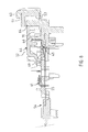
- Figures 1 to 5 show a control handle for a wiper switch.
- a wiper switch generally includes a housing in which of the contacts can be actuated by the control lever to realize the different functions; the switch is mounted on a support block crossed by the steering shaft; the switch housing is mounted inside of the support block, only the control lever of the switch leaving the block by a slit which it presents.
- the wiper switch handle is made up externally a lever body 1, rotatable in a plane parallel to the steering wheel and in the plane that the joystick defines with the steering column, said plane of the column steering, a rotating ring 8, a central support 2, a cap 9, a rocker button 3 and a wheel 6, the rocker button 3 and the wheel 6 being at the end, at the free end of the joystick.
- the lever body 1 In the plane parallel to the steering wheel, the lever body 1 has a stable neutral position, one unstable position by moving down and three stable positions by moving up.
- the downward movement corresponds to the activation of the wiper pulse.
- the successive upward movements correspond respectively when the intermittent wiper, low speed, high speed is activated.
- the body 1 of the switch In the plane of the steering column, the body 1 of the switch has a stable neutral position and an unstable position. Maintaining the switch in unstable position operates the front window washer.
- the ring 8 has two stable positions and an unstable position.
- a stable position is the neutral position, and the second stable position is that of rear wiper operation. Beyond this second position stable, the unstable position corresponds to the operation of the rear window washer.
- this free end part comprises at least one control device for at least one of the functions performed by an appliance on-board audio in a vehicle, such as a radio, music player cassettes or CDs.
- the central support 2, surrounded by the ring 8, is fitted into the body 1, of which it is integral, thanks to at least one axial tongue 12 which it has, FIG. 3, and which cooperates by clipping with the internal wall 13 of the body 1.
- the central support 2 comprises a cylindrical skirt 21 and a bottom 22; the skirt 21 is therefore open towards the free end of the lever.
- the skirt 21 internally carries two axial grooves 23 diametrically opposite in which is mounted, by its lateral edges, a plate 14 of general rectangular shape.
- the plate 14 in place is in axial abutment against the bottom 22 of the central support; it is axially longer than the skirt 21 and its part which emerges from the central support 2 is capped by the cap 9 secured to the support central 2, at the end thereof, for example by clipping.
- the plate 14 is generally made of non-conductive material and comprises a cut conductive circuit 15 embedded in the non-conductive material and the external faces 16, 17 of the plate 14 have received conductive tracks, linked electrically to the conductor circuit 15.
- the plate 14 has an opening 18 in its part close to the bottom 22 central support 2; thanks to this opening 18, the conductive circuit 15 has tabs 19, here three tabs 19, the free end of which protrudes relative to the opening 18. These tabs 19 cooperate with tracks 24 a connector 20 extended along pins 25 to which are connected connecting conductors electrically connecting the plate 14 to the audio device.
- the connector 20 is mounted by clipping into an axial well 26 carried by the bottom 22 of the central support 2.
- the plate 14 Towards the free end of the lever, the plate 14 has on one side, here of the side of its face 16, a housing 27 and on the other side a pivot 30; housing 27 receives the axis 28 of the rocking button 3 around which it can rock to one side or the other ; a leaf spring 5, figure 5, allows the rocker button to stay at rest in its middle position; the pivot 30 allows the rotary mounting of the dial 6.
- the tilting button 3 carries on its face turned towards the plate 14 a cursor, not shown, which cooperates with fingers, such as finger 29, figure 4, from the driver circuit 15.
- the dial 6 and the plate 14 include complementary electrical means not shown allowing the dial 6, by turning around the pivot 30, to intervene on the driver circuit 15.
- rocker button 3 or the thumbwheel 6 means complementary electrics could be sliders, operated mechanically via the rocker button 3 or the dial 6, cooperating with conductive tracks formed on the faces 16 and 17 of the platinum 14.
- rocking button 3 and the dial 6 are axially partly projecting relative to the cap 9, for their gripping, by means of openings 31, 32 presented in hat 9.
- the button tilting 3 could, by a command of the pulse type, command, for one direction of tilting, increasing the volume and, for the other direction, the decrease in it.
- the dial 6 could allow, by rotation, to have access to preset stations.
- rocker button 3 can be any function to be set previously selected on the audio device itself.
- the plate 54 is also generally made of non-conductive material and includes a conductive circuit 55 cut out embedded in the non-conductive material; here the driver circuit 55 incorporates connection elements 50 ensuring the electrical connection of the plate 54 via a connector 56.
- the plate 54 On one of its faces, the plate 54 receives a control lever 44, associated with a control button 43 clipped to the lever 44 at the end of the latter ; of course, the lever 44 and the key 43 could be in one piece.
- the lever 44 is adapted to cooperate with a so-called contact blade 45 by through which the electrical functions are provided.
- the contact blade 45 is generally U-shaped having a bottom 46 and two wings or lateral arms 47, 48; the bottom 46 extends in a plane overall perpendicular to the plate 54 with respect to which it is arranged transversely.
- the bottom 46 of the contact blade 45 On its edge facing the plate 54, the bottom 46 of the contact blade 45 has a claw cutout intended to take place in suitable housings for fixing the bottom 46 on the plate 54.
- the control lever 44 is in the general shape of a T having a head 51 and a leg 52; the control lever 44 is mounted articulated on the plate 54; here, this articulation assembly is obtained by cooperation of a pin 64 of the plate 54 with a housing 53 formed in the control lever 44; in the shape shown, the housing 53 is formed in the head 51 of the lever command 44 and is oblong in shape, for the reasons described below.
- leg 52 of the control lever 44 At the end of the leg 52 of the control lever 44 are provided laterally, on either side thereof, two heels 59, 60 respectively; by tilting the control lever 44 around the pin 64, by action on the key 43, for example anticlockwise, the heel 59 of leg 52 of control lever 44 acts on lateral arm 47 of the contact blade 45 so that this lateral arm 47 leaves the support 57 to come in contact, FIG. 9, of a so-called contact pad 67, of the associated driver circuit 55 to a resistor of a resistive network 61 for coding the function corresponding.
- the tilting movement of the control lever 44 is limited by bosses 62, 63 of stroke limitation with which are adapted to cooperate lateral bearing surfaces 65, 66 formed on the head 51 of the control lever 44.
- the pin 64 being mounted in an oblong-shaped housing 53, the head 51 of the control lever 44 is biased towards the outside of the plate 54, by a leaf spring 70, so that a rotation around the pin 64 can be assured.
- the oblong shape of the housing 53 extends along the axis of the leg 52 of the control lever 44: thanks to this arrangement, it is possible to move the control lever 44 in translation by pushing the key 43, against the action leaf spring 70, and provide a third function.
- the contact blade 45 has a transverse arm 49, issuing laterally from its bottom 46, which rests at its end on a support 65 carried by plate 54, figure 7.
- the control lever 44 is adapted to cooperate with this transverse arm 49 by means of a stud 69 carried by its leg 52; by pushing axially the key 43, FIG. 10, the stud 69 acts on the transverse arm 49 so that it leaves the support 65 to come into contact with a contact pad 66 also associated with a resistor from the resistive network 61 for coding the function correspondent; the thrust stroke of the control lever 44 is limited by the housing 53 of oblong shape.
- the volume of the radio could be cut and then reset by pressing again.
- the dimensioning of the parts concerned is such that it is impossible to make two electrical contacts simultaneously; for example, if we push the key 43 while the control lever 44 is in the tilting position, the heel 59 or 60 concerned leaves the lateral arm 47 or 48 before the nipple 69 come and push the transverse arm 49.
- the leaf spring 70 is mounted transversely in an arcuate manner, its ends being arranged in V-shaped slots 72, 73 being face and formed respectively in the bosses 62, 63 of the plate 54.
- the leaf spring 70 present in its part central folding defining a V, Figure 11, the wings 74, 75 meet according to a semi-circular bottom 76.
- a notch 77 symmetrically bordered on each side by inclined flanks 78, 79; the sides 78, 79 form an angle between them which is greater to that formed between them by the wings 74, 75 of the central part of the spring blade 70 so that these cooperate with the edges 80, 81 of intersection sides 78, 79 and notch 77.
- the plate 54 is adapted to receive on its opposite face another control lever 44 and its button control 43 associated with another contact blade 45 and another spring at blade 70, so as to perform three other electrical functions.
Landscapes
- Engineering & Computer Science (AREA)
- Mechanical Engineering (AREA)
- Switches With Compound Operations (AREA)
Applications Claiming Priority (2)
| Application Number | Priority Date | Filing Date | Title |
|---|---|---|---|
| FR0015068 | 2000-11-22 | ||
| FR0015068A FR2816893B1 (fr) | 2000-11-22 | 2000-11-22 | Manette de commutateur de haut de colonne de direction de vehicule automobile a organe (s) de commande d'un appareil audio embarque et commutateur equipe d'une telle manette |
Publications (2)
| Publication Number | Publication Date |
|---|---|
| EP1209029A1 true EP1209029A1 (de) | 2002-05-29 |
| EP1209029B1 EP1209029B1 (de) | 2010-09-08 |
Family
ID=8856752
Family Applications (1)
| Application Number | Title | Priority Date | Filing Date |
|---|---|---|---|
| EP20010402980 Expired - Lifetime EP1209029B1 (de) | 2000-11-22 | 2001-11-21 | Lenkstockschaltereinrichtung für Kraftfahrzeuge |
Country Status (3)
| Country | Link |
|---|---|
| EP (1) | EP1209029B1 (de) |
| DE (1) | DE60143012D1 (de) |
| FR (1) | FR2816893B1 (de) |
Cited By (2)
| Publication number | Priority date | Publication date | Assignee | Title |
|---|---|---|---|---|
| EP1864856A1 (de) * | 2006-06-02 | 2007-12-12 | Yazaki Corporation | Hebelschalter |
| WO2010000860A1 (fr) * | 2008-07-03 | 2010-01-07 | Sc2N | Module de commande pour un levier d'un ensemble de commande sous-volant, et levier associé |
Families Citing this family (1)
| Publication number | Priority date | Publication date | Assignee | Title |
|---|---|---|---|---|
| JP6557201B2 (ja) * | 2016-09-28 | 2019-08-07 | 矢崎総業株式会社 | 車載機器操作装置 |
Citations (7)
| Publication number | Priority date | Publication date | Assignee | Title |
|---|---|---|---|---|
| EP0629526A1 (de) * | 1993-06-16 | 1994-12-21 | Silvano Di Francesco | Schalthebelgriffeinheit für Kraftfahrzeuge |
| FR2731552A1 (fr) | 1995-03-09 | 1996-09-13 | Magneti Marelli France | Commutateur electrique notamment pour la commande d'autoradios et procede de fabrication a cet effet |
| DE19706546A1 (de) | 1996-02-20 | 1997-08-21 | Alps Electric Co Ltd | Fahrzeug-Knaufschaltervorrichtung |
| US5724719A (en) * | 1992-11-06 | 1998-03-10 | Itt Corporation | Method of manufacturing a steering column stalk switch apparatus |
| DE19723482C1 (de) * | 1997-06-04 | 1998-06-25 | Kostal Leopold Gmbh & Co Kg | Elektrischer Dreh-/Schubschalter |
| DE19722780C1 (de) | 1997-06-02 | 1998-11-12 | Kostal Leopold Gmbh & Co Kg | Elektrische Drehschaltereinheit |
| DE19740526C1 (de) * | 1997-09-15 | 1999-02-11 | Siemens Ag | Betätigungsvorrichtung, insbesondere für Lenkstockhebel in Kraftfahrzeugen, zur Realisierung von Schaltfunktionen und Verfahren zur Anwendung einer solchen Betätigungsvorrichtung |
-
2000
- 2000-11-22 FR FR0015068A patent/FR2816893B1/fr not_active Expired - Fee Related
-
2001
- 2001-11-21 DE DE60143012T patent/DE60143012D1/de not_active Expired - Lifetime
- 2001-11-21 EP EP20010402980 patent/EP1209029B1/de not_active Expired - Lifetime
Patent Citations (7)
| Publication number | Priority date | Publication date | Assignee | Title |
|---|---|---|---|---|
| US5724719A (en) * | 1992-11-06 | 1998-03-10 | Itt Corporation | Method of manufacturing a steering column stalk switch apparatus |
| EP0629526A1 (de) * | 1993-06-16 | 1994-12-21 | Silvano Di Francesco | Schalthebelgriffeinheit für Kraftfahrzeuge |
| FR2731552A1 (fr) | 1995-03-09 | 1996-09-13 | Magneti Marelli France | Commutateur electrique notamment pour la commande d'autoradios et procede de fabrication a cet effet |
| DE19706546A1 (de) | 1996-02-20 | 1997-08-21 | Alps Electric Co Ltd | Fahrzeug-Knaufschaltervorrichtung |
| DE19722780C1 (de) | 1997-06-02 | 1998-11-12 | Kostal Leopold Gmbh & Co Kg | Elektrische Drehschaltereinheit |
| DE19723482C1 (de) * | 1997-06-04 | 1998-06-25 | Kostal Leopold Gmbh & Co Kg | Elektrischer Dreh-/Schubschalter |
| DE19740526C1 (de) * | 1997-09-15 | 1999-02-11 | Siemens Ag | Betätigungsvorrichtung, insbesondere für Lenkstockhebel in Kraftfahrzeugen, zur Realisierung von Schaltfunktionen und Verfahren zur Anwendung einer solchen Betätigungsvorrichtung |
Cited By (4)
| Publication number | Priority date | Publication date | Assignee | Title |
|---|---|---|---|---|
| EP1864856A1 (de) * | 2006-06-02 | 2007-12-12 | Yazaki Corporation | Hebelschalter |
| US7692109B2 (en) | 2006-06-02 | 2010-04-06 | Yazaki Corporation | Lever switch |
| WO2010000860A1 (fr) * | 2008-07-03 | 2010-01-07 | Sc2N | Module de commande pour un levier d'un ensemble de commande sous-volant, et levier associé |
| FR2933343A1 (fr) * | 2008-07-03 | 2010-01-08 | Sc2N Sa | Module de commande pour un levier d'un ensemble de commande sous-volant,et levier associe |
Also Published As
| Publication number | Publication date |
|---|---|
| FR2816893A1 (fr) | 2002-05-24 |
| DE60143012D1 (de) | 2010-10-21 |
| FR2816893B1 (fr) | 2003-05-30 |
| EP1209029B1 (de) | 2010-09-08 |
Similar Documents
| Publication | Publication Date | Title |
|---|---|---|
| EP1049398B1 (de) | Elektrisch betriebenes haushaltsgerät, insbesondere handmixer | |
| FR2784592A1 (fr) | Dispositif de freinage pour vehicule motorise de neige | |
| EP1209029B1 (de) | Lenkstockschaltereinrichtung für Kraftfahrzeuge | |
| US5182423A (en) | Electric switch for operating a windshield wiper and washer system of a motor vehicle | |
| EP2978006B1 (de) | Elektrischer schalter | |
| EP0919436B1 (de) | Unter dem Lenkrad angeordneter, elektrischer Steuerungsschalthebel | |
| FR3089658A1 (fr) | Dispositif de commande d’un appareil électronique, procédés de réglage du dispositif et rétroviseur de véhicule automobile intégrant un tel dispositif. | |
| FR2509517A1 (fr) | Dispositif de commutation a depassement comportant un mecanisme de transmission a came et a lame pivotante | |
| EP0989031B1 (de) | Elektronisches Lenksäulenoberteil | |
| EP0840337B1 (de) | Schaltermechanismus | |
| EP2398029B1 (de) | Schalter mit monostabiler Bedienung und bistabilem Kontakt | |
| FR2577712A1 (fr) | Interrupteur de protection | |
| EP1732096B1 (de) | Schwenkhebelsteuereinrichtung mit reduziertem Winkelbereich | |
| EP1393336B1 (de) | Steuereinrichtung für ein kraftfahrzeug insbesondere zur steuerung eines onboard-computers | |
| FR2496022A1 (fr) | Dispositif de commande pour avertisseurs optiques et sonores | |
| EP0533565B1 (de) | Verbesserter elektrischer Kommutator für Kraftfahrzeuge | |
| FR2648615A1 (fr) | Perfectionnements aux interrupteurs a coupure automatique, notamment aux disjoncteurs et disjoncteurs differentiels | |
| EP0887230A1 (de) | Lenkstockschalteranordnung für Kraftfahrzeuge | |
| FR2473221A1 (fr) | Commutateur electrique a mecanisme limitant les fausses manoeuvres | |
| EP1486376B1 (de) | Steueranordnung zum Aktivieren bzw. Deaktivieren von Funktionen eines Fahrzeuges | |
| EP4297057A1 (de) | In gleichrichtung doppelt betätigte kippsteuerungsvorrichtung mit haptischer rückkopplung mit doppelter auslösung | |
| EP0194917B1 (de) | Mehrzweckschalter für Kraftfahrzeuge | |
| FR2533747A1 (fr) | Commutateur electrique a action brusque et ensemble de commutation forme de plusieurs commutateurs | |
| EP0703592A1 (de) | Elektrischer Schalter für die Versorgung des Standlichts eines Kraftfahrzeugs | |
| FR2793067A1 (fr) | Commutateur electrique multiple a organe d'actionnement unique |
Legal Events
| Date | Code | Title | Description |
|---|---|---|---|
| PUAI | Public reference made under article 153(3) epc to a published international application that has entered the european phase |
Free format text: ORIGINAL CODE: 0009012 |
|
| AK | Designated contracting states |
Kind code of ref document: A1 Designated state(s): AT BE CH CY DE DK ES FI FR GB GR IE IT LI LU MC NL PT SE TR |
|
| AX | Request for extension of the european patent |
Free format text: AL;LT;LV;MK;RO;SI |
|
| 17P | Request for examination filed |
Effective date: 20020727 |
|
| AKX | Designation fees paid |
Designated state(s): DE ES FR GB IT |
|
| 17Q | First examination report despatched |
Effective date: 20071217 |
|
| GRAP | Despatch of communication of intention to grant a patent |
Free format text: ORIGINAL CODE: EPIDOSNIGR1 |
|
| GRAS | Grant fee paid |
Free format text: ORIGINAL CODE: EPIDOSNIGR3 |
|
| GRAA | (expected) grant |
Free format text: ORIGINAL CODE: 0009210 |
|
| RAP1 | Party data changed (applicant data changed or rights of an application transferred) |
Owner name: VALEO INTERIOR CONTROLS |
|
| AK | Designated contracting states |
Kind code of ref document: B1 Designated state(s): DE ES FR GB IT |
|
| REG | Reference to a national code |
Ref country code: GB Ref legal event code: FG4D Free format text: NOT ENGLISH |
|
| REF | Corresponds to: |
Ref document number: 60143012 Country of ref document: DE Date of ref document: 20101021 Kind code of ref document: P |
|
| PG25 | Lapsed in a contracting state [announced via postgrant information from national office to epo] |
Ref country code: IT Free format text: LAPSE BECAUSE OF FAILURE TO SUBMIT A TRANSLATION OF THE DESCRIPTION OR TO PAY THE FEE WITHIN THE PRESCRIBED TIME-LIMIT Effective date: 20100908 |
|
| PG25 | Lapsed in a contracting state [announced via postgrant information from national office to epo] |
Ref country code: ES Free format text: LAPSE BECAUSE OF FAILURE TO SUBMIT A TRANSLATION OF THE DESCRIPTION OR TO PAY THE FEE WITHIN THE PRESCRIBED TIME-LIMIT Effective date: 20101219 |
|
| PLBE | No opposition filed within time limit |
Free format text: ORIGINAL CODE: 0009261 |
|
| STAA | Information on the status of an ep patent application or granted ep patent |
Free format text: STATUS: NO OPPOSITION FILED WITHIN TIME LIMIT |
|
| 26N | No opposition filed |
Effective date: 20110609 |
|
| REG | Reference to a national code |
Ref country code: DE Ref legal event code: R097 Ref document number: 60143012 Country of ref document: DE Effective date: 20110609 |
|
| REG | Reference to a national code |
Ref country code: FR Ref legal event code: PLFP Year of fee payment: 15 |
|
| REG | Reference to a national code |
Ref country code: FR Ref legal event code: PLFP Year of fee payment: 16 |
|
| PGFP | Annual fee paid to national office [announced via postgrant information from national office to epo] |
Ref country code: GB Payment date: 20161121 Year of fee payment: 16 |
|
| REG | Reference to a national code |
Ref country code: FR Ref legal event code: PLFP Year of fee payment: 17 |
|
| GBPC | Gb: european patent ceased through non-payment of renewal fee |
Effective date: 20171121 |
|
| PG25 | Lapsed in a contracting state [announced via postgrant information from national office to epo] |
Ref country code: GB Free format text: LAPSE BECAUSE OF NON-PAYMENT OF DUE FEES Effective date: 20171121 |
|
| PGFP | Annual fee paid to national office [announced via postgrant information from national office to epo] |
Ref country code: DE Payment date: 20201109 Year of fee payment: 20 Ref country code: FR Payment date: 20201130 Year of fee payment: 20 |
|
| REG | Reference to a national code |
Ref country code: DE Ref legal event code: R071 Ref document number: 60143012 Country of ref document: DE |